LTV LTV-S7208E-POE User manual

LTV Europe Sicherheitstechnik GmbH
Am Wall 113
28195 Bremen
www.ltv-cctv.eu
support@ltv-cctv.eu
The LTV Europe Sicherheitstechnik GmbH as the publisher of this document, provi-
des no warranties related to the accuracy, completeness and topicality of the cont-
ent. The LTV Europe Sicherheitstechnik GmbH furthermore reserves the right to pub-
lish updated and revised versions of this document without prior notice. The names,
tradenames, trademarks etc. described in this work are used without guarantee of
free usability, and may be registered trademarks or brands without specic labelling,
and as such may be subject to legal regulations. This work is protected by copyright.
All rights, including the right to reproduce, reprint and the distribution and transla-
tion of this document, or parts thereof, are reserved. No part of this document may
be in any way reproduced, or electronically stored, processed, copied or distributed,
without written permission of the publisher or author, not even for the purpose of
teaching. All rights reserved.
© 2015 Version 01/2015
Quick Installation Guide
8 Port PoE Ethernet Switch
LTV-S7208E-POE
LTV Europe Sicherheitstechnik GmbH
Am Wall 113
28195 Bremen
Germany
www.ltv-cctv.eu

LTV-S7208E-POE
This switch provides a uplink ethernet port and one optical port 1000Mbps;
8 100Mbps PoE ethernet ports support af/at standard. This product is desi-
gned for HD IP Cameras. It makes the connection of those devices far away
from the power more exible and simplies wiring. This product contains a
optical port to realize perfect integration between ber optical transceiver
and ethernet switch and by this solves the problem of long distance trans-
mission.
Features
Eight 10/100Mbps PoE ethernet ports, support power supply for the net-
work device meet IEEE802.3 af/at standard.
PoE network port support IEEE802.3 af/at standard, it can provide 30W
consumption and power supply to the big consumption infrared camera.
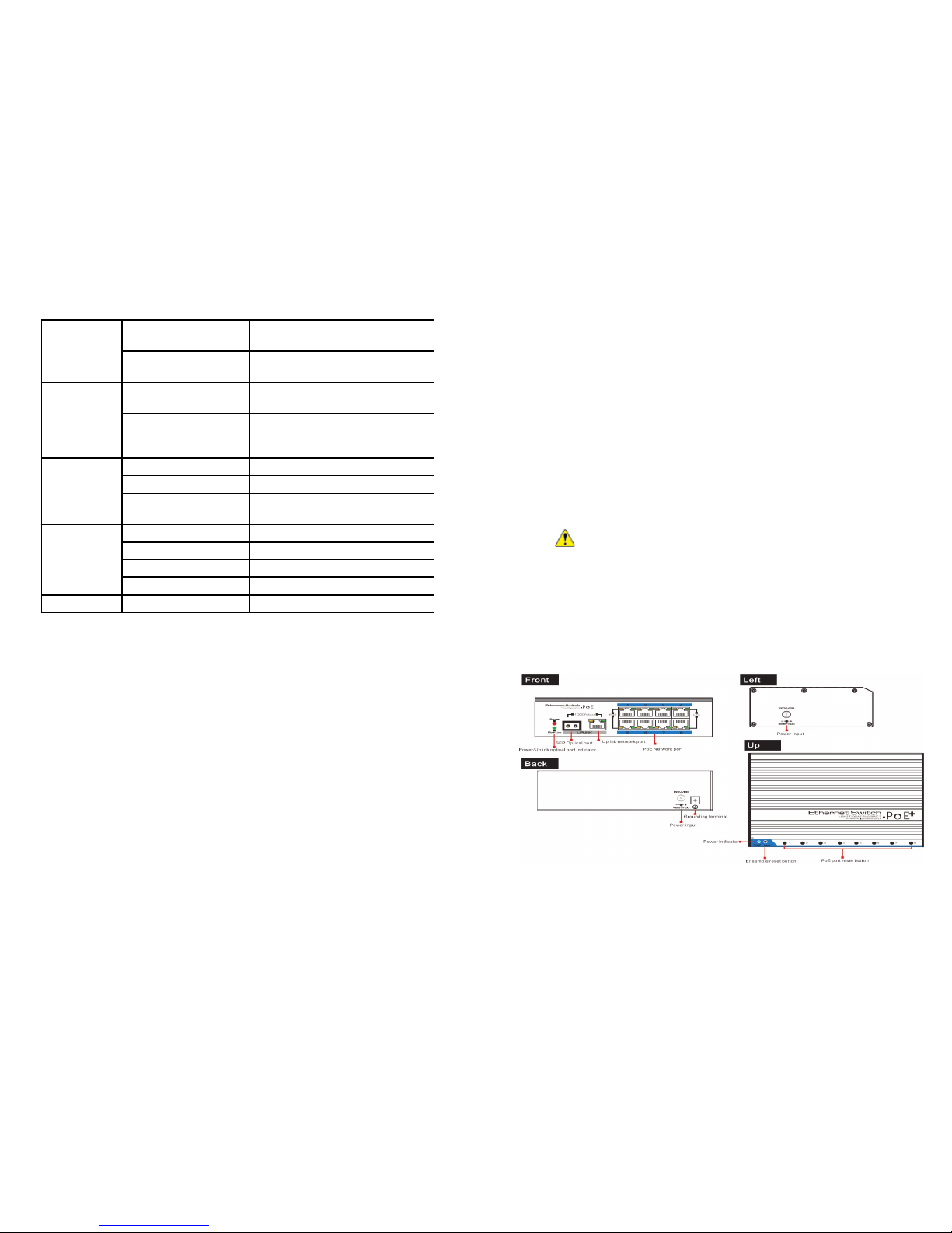
If provides 2 uplink ports, 1000Mbps optical port and ethernet port. Uplink
ethernet port can connect with NVR and other high bandwidth device con-
veniently. Uplink optical port reserve SFP port for users to select dierent
performance SFP optical ber module, conveniently solving the problem of
long distance transmission.
The switch and every PoE ethernet port does have a reset button for users
to solve IP camera crash and others problem, no need to pullout and plug
network cables. The reset button is on the bevel.
Notice
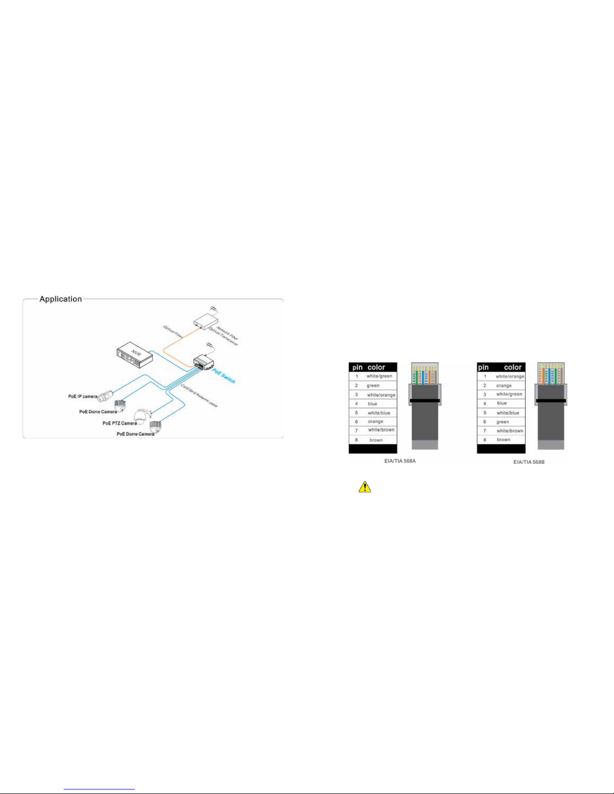
When choose RJ-45 make sure if one end is EIA/TIA568A,the other end
should also be EIA/TIA568A.
When choose RJ-45 make sure if one end is EIA/TIA568B,the other end
should also be EIA/TIA568B.
RJ 45 Making Method
Instruments to be used: wire crimper, network tester. Wire sequence of RJ45
plug should conform with EIA/TIA568A or 568B.
1) Shuck o about 2cm long the insulating layer, and bar the 4 pairs UTP
cable.
2) Depart the 4 pairs UTP cable and straighten them.
3) Line up the 8 pieces of cables per EIA/TIA 568A or 568B.
4) Cut out 1.5 cm cable wrap and leave the bare wire.
5) Plug 8 cables into RJ45 plug, make sure each cable is in each pin.
6) Then use wire crimper to crimp it.
7) Follow the 5 steps above to make the another end, following the same
sequence of the rst plug.
8) Using network tester to test the cable whether is working.

Button
PoE Reset Button 8,corresponding with 1~8 port, PoE
reset after press the button
Reset Button 1, switch restart after press this
button
Protection
Communication port
Lightning protection 4KV per: IEC61000-4-5
ESD
1a contact discharge 3 level
1b air discharge 3 level
Per:IEC61000-4-2
Environmental
Working temperature -40°C~75°C
Storage temperature -40°C~75°C
Humidity (non-conden-
sing) 0~95%
Mechanical
Dimension (L×W×H) 159mm×110mm×46.5mm
Material Aluminum
Color Black
Weight 570g
Stability MTBF >200000h
Product are subject to change without prior notice
Trouble Shooting
Please nd the following solution when the device doesn‘t work
Please conrm if the installation is correct.
Please conrm if the RJ45 cable order in accordance with the EIA/TIA568A
or 568B industry standards.
The maximum consumption of every PoE port can supply to the PoE device
can‘t over 30 W, please do not use the PoE device which consumption over
30W.
Please replace a normal device with a failure one to check if the device is
broken. If the problem still exist, please contact your local dealer.
The transmission distance of uplink ethernet port can up to 150m.
Up to 1M Package data cache, making more smooth of forwarding high-ca-
pacity data.
Up to 8K for the MAC address, easily for system upgrade.
Support IEEE802.3X full duplex ow control; support (Auto MDI/MDIX)
function.
Redundance power design, power heat backup or raise power consump-
tion. Industrial standard product, fold metal outershell heat dissipation
without fan designed. Installation fast, easily operation, convenient for wall,
din rail and desktop installation.
Notice
1) Transmission distance is related to the connecting cable. We suggest to
use standard Cat5e/6 network cable to get the 150m transmission distance.
2) If using optical port, customer need to purchase SFP module additional.
Board diagram

Description:
Front board with PoE ethernet port, the yellow light on the RJ 45 socket
left side is to indicate the PoE status, the green light on the right side is to
indicate network status: The yellow light and green light on the Uplink net-
work RJ 45 socket is to indicate network working status. The LED on the SFP
optical port left side is to indicate power and optical port working status.
Installation steps
Please check the following items before installation.
If any missing, please contact the dealer.
POE ethernet switch 1pc
MIT hangers 2pc
Din rail hanger 1pc
User manual 1pc
Please follow the following installation steps
1) Please turn o the signal source and the device‘s power, installation with
power on may damage the device.
2) Use 8 network cables to connect 8 IP cameras with POE switch‘s1~8PoE
port.
3) Use another network cable or (optical ber) to connect PoE ethernet
switch’s UPLINK port with NVR or computer.
4) Connect PoE switch with power adapter.
5) Check if the installation is correct and device is good, make sure all the
connection is reliable and power up the system.
6) Make sure every network device has power supply and work normally.
Specication
Item Description
Power
Power Supply Power Adapter DC48V 1.25A
Power Adapter Voltage DC 48V-57V
Power Consumption <5W
Network
Connector
Network Port
1-8 port:10/100Mbps PoE
network port
UPLINK port:10/100/1000Mbps
network port
SFP:1000Mbps optical ber SFP
module port
Transmission Distance
1-8 port:150m
UPLINK port: 150m
SFP: depend on the optical module
transmission performance
Transmission Medium Cat5e/6 standard network cable
PoE Protocol IEEE802.3af/at
PoE Power Supply End-span
PoE Power Consumption Every PoE port output <30W;
Network
Switch
Network Standard
IEEE802.3 10BASE-T,IEEE802.3u
100BASE-TX, IEEE802.3ab 1000BA-
SE-TX;
IEEE802.3z 1000-SX/LX;
IEEE802.3 X
Switch way Store and forward
Package data cache 1M
MAC address list 8K
LED Status
Indicators
Power indicator 1 (red) on the front board; 1(red) on
the lean board
Optical port LED
indicator 1 SPF port indicator (green)
Uplink network port LED
indicator 1 (green on the RJ 45 socket)
PoE network LED
indicator
8 PoE status indicator (yellow on the
RJ 45 socket)
Other LTV Network Router manuals
Popular Network Router manuals by other brands

Vitrum
Vitrum Home Master Handbook

KYLAND Technology
KYLAND Technology SICOM3000A Series Hardware installation manual

Hypercable
Hypercable SkyMesh HYC-OLTRG-100GN-27 user manual

ADTRAN
ADTRAN ATLAS 550 quick start guide

Ubiquiti
Ubiquiti EdgeRouter 10X quick start guide

Danfoss
Danfoss VLT AutomationDrive manual

NETGEAR
NETGEAR JFS516GE installation guide

Allied Telesis
Allied Telesis AT-8000S Series Cli reference guide

Cisco
Cisco ASR 14000 Series Command reference

Seethelight
Seethelight Thomson TG585 Upgrade guide

Zte
Zte ZXHN F660 Description

ZyXEL Communications
ZyXEL Communications Dimension GS-3012 Cli reference guide