Lucent Technologies TransTalk 9000 User manual

TRANSTALK 9000
MDC 9000 Cordless Telephone
Installation
503-801-101
Issue 1
May 1994

Copyright ©1994 AT&T AT&T 503-801-101
All Rights Reserved
Issue 1
Printed in U.S.A.
May 1994
Notice
Every effort was made to ensure that the information in this booklet was
complete and accurate at the time of printing. However, information is
subject to change.
Federal Communications Commission (FCC) Information
For details, see “FCC Information.”
Security
As a customer of new telecommunications equipment, you should be aware
of the significant and growing problem of theft of long distance services by
third parties, known commonly as toll fraud. It is particularly important that
you understand and take appropriate steps to deal with this crime because
under applicable tariffs, you will be responsible for payment of associated
toll charges. AT&T cannot be responsible for such charges and will not
make any allowance or give any credit resulting from toll fraud. Toll fraud
can occur despite the preventive efforts of network providers and equip-
ment manufacturers.
Toll fraud is a potential risk for every customer with telecommunications
equipment having one or more of the following features: (1) remote access,
(2) automated attendant, (3) voice mail, (4) remote administration and
maintenance, and (5) call forwarding (remote). This is not a product or
design defect, but a risk associated with equipment having one or more of
the features described above. If your new telecommunications equipment
possesses any of these features, please consult the relevant portion of your
documentation for further details and specific procedures to reduce the risk
of toll fraud or contact your AT&T dealer for further details.
Trademarks
PARTNER, MERLIN, MERLIN LEGEND, DEFINITY and SYSTIMAX are
registered trademarks of AT&T. Supra is a registered trademark of
Plantronics, Inc.
Warranty
AT&T provides a limited warranty for this phone; see “AT&T Limited
Warranty.”
Ordering Information
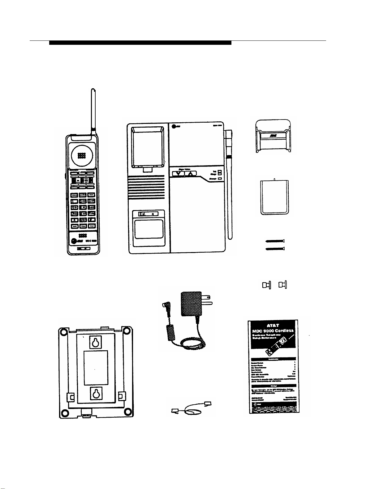
The order number for this booklet is 503-801-101. The order number for the
MDC 9000 Cordless Business Telephone Quick Reference is 503-801-100.
To order additional copies of these reference materials, call 1 800 432-6600
(in Canada 1 800 255-1242). To order parts and accessories, see “Ordering
Replacement & Optional Parts.”
Support Telephone Numbers
In the U.S., AT&T provides a toll-free customer helpline 24 hours a day. Call
the AT&T Helpline at 1 800 628-2888 if you need assistance when installing,
programming, or using your cordless phone.
For assistance in Canada, contact your local AT&T Authorized Dealer.

Contents
Introduction
■ Privacy Information
■ Automatic Security Coding
■ Safety Information
Parts List
Installation
1
2
2
2
3
■
■
■
■
■
■
■
■
■
■
■
Important Safety Instructions
Additional Safety Instructions for Installation Personnel
Base Connectors
Positioning the Base
Installing the Base a Desk
Installing the Base on a Wall
Inserting and Removing the Battery Pack
Charging the Battery
Replacing the Battery Pack
Testing the Installation
Filling Out Labels
4
4
7
8
9
11
13
17
19
19
20
21
Handset Range Indicators
Using the Carrying Holster
Headsets
■ Using a Headset
MDC 9000 Compatibility
■ Entering Station Programming Mode
■ Programming Sytem Features
Maintaining Your MDC 9000
Ordering Replacement & Optional Parts
22
23
24
24
26
26
27
32
32

Introduction
Congratulations on the purchase of your new
MDC 9000 Cordless
Business Telephone,
MDC stands for Multi-line Digital Cordless.
Advanced radio technology and digital transmission provides more
power, extended range, greater clarity, and higher security. This
phone was designed to AT&T's high standards for reliability and
convenience.
The
handset
is portable. This portability enables you to move
about your work area or home with freedom, without giving up the
features of a corded phone.
An optional headset can be connected to the handset to allow
hands-free conversation. For ordering information, see “Ordering
Replacement & Optional Parts.”
This booklet describes MDC 9000 installation. Also included with
the phone is a Quick Reference that contains information about
displays, controls, base connectors, compatibility and trouble-
shooting.
After you have installed your phone and understand its controls
and displays, use the programming and call handling instructions
that come with your phone system. Follow the user instructions for
the phone type identified below:
■
PARTNER
®
systems: the MLC-6 Cordless Telephone:
the MDC
9000 is fully compatible with the PARTNER family of phone
systems.
■
MERLIN
®
, MERLIN Plus, and MERLIN II systems: a 5-button
phone.
■
■
■
MERLIN LEGEND
®
systems: a 10-button ATL set.
System 25: a 10-button set.
System 75, System 85, and DEFINITY
®
systems: a 7303s set.
Refer to “MDC 9000 Compatibility” later in this booklet for a list of
functional differences when using a MERLIN, MERLIN Plus,
MERLIN II, MERLIN LEGEND, System 25, System 75, System 85,
or DEFINITY phone system.
1

Privacy Information
This telephone is designed to protect the privacy and security of
your voice conversation. The set uses continuously changing radio
frequencies and digital encoding techniques to make it impossible
for eavesdropping to occur through the use of commercially
available analog radio scanners.
Automatic Security Coding
This telephone has a digital security code that is automatically
changed every time you place the handset in the base unit for 10
seconds or more. This code prevents unauthorized use of your line
and also prevents a user with another cordless handset from
dialing calls on your line.
Safety Information
Before installing the telephone, please read and understand the
safety instructions in “Installation.” This booklet also contains
instructions related to safety labels on the product:
WARNING indicates the presence of a hazard that can
cause severe or fatal personal injury if the hazard is not
avoided.
CAUTION indicates the
can cause minor personal
avoided.
presence of a hazard that will or
injury or property damage if not
2

Parts List
Along with this booklet, the box should contain the items shown
below. If it does not, call the AT&T Helpline at 1 800 628-2888. In
Canada, contact your local AT&T Authorized Dealer.
Handset
Mounting Stand
Base
7-foot (2.3 m)
Power Cord and
Standard AC Adapter
14-foot (4.6 m)
Telephone Line Cord
Carrying Holster
Battery Pack
Phillips Head
Wood Screws (2)
Mounting Sleeves (2)
Quick Reference
3

Installation
IMPORTANT:
Before beginning installation, please read and understand
“Important Safety Instructions” and “Additional Safety Instructions
for Installation Personnel” on the following pages.
Important Safety Instructions
Always follow these basic safety precautions when installing or
using this product to reduce risk of injury from fire or electric
shock.
Make
sure that the base is unplugged before you install.
The exclamation point within an equilateral triangle Is
intended to alert the user to the presence of important
operating and maintenance (servicing) instructions in
the literature accompanying the product.
WARNING: Risk of Electric Shock
Failure to properly ground this product will result in a risk of
electrical shock, which can cause serious personal injury.
This product requires a 3-prong AC power receptacle for
safe operation. You should have your receptacle checked
by a qualified electrician before connecting this equipment.
WARNING:
The Rechargeable battery contains nickel and cadmium. Do
not burn or puncture the battery. Like other batteries of this
type, if it is burned or punctured, it could release toxic
material which could cause injury. Do not dispose of it in
household garbage. For information about recycling or
proper disposal, consult your local solid waste (garbage)
collection or disposal organization.
SAVE THESE INSTRUCTIONS
4

■
■
■
■
■
Read and understand all instructions in this booklet before
using this product.
Observe all warnings and instructions marked on the product.
Unplug this product from wall outlets and telephone jacks
before cleaning. Clean exposed parts with a soft, damp cloth.
Do not use liquid or aerosol cleaners.
Do not use the product near water or when you are wet. If the
product comes in contact with any liquids, unplug the power
cord and telephone line cords immediately. Do not plug the
product back in until it has dried thoroughly.
■
■
■
■
■
If you suspect a gas leak, report it immediately, but use a
telephone away from the area in question. The telephone’s
electrical contacts could generate a tiny spark. While unlikely, it
is possible that this spark could ignite a heavy concentration of
gas. This product is not approved for use in areas labeled by
the Occupational Safety and Health Administration (OSHA) as
“explosive environments.” Only “Explosive Atmosphere Tele-
phones” may be used in such hazardous environments.
Never push objects of any kind into this telephone through
housing slots, since the objects may touch hazardous voltage
points or short out parts that could result in a risk of electric
shock. Never spill liquid of any kind on the telephone.
Install this product securely on a stable surface. Damage may
result if the product falls.
Install this product in a protected location where no one can
step on or trip over power and line cords. Do not place objects
on the cords that may cause damage or abrasion.
Use only the Model GBCS power supply shipped with
this product.
Use only the correct power source. If you are not sure of the
power supply to your location, consult your local power
company.
5

■
■
■
■
Use only the battery pack model indicated in “Ordering &
Optional Parts.”
This device uses a 3-prong plug in continental U.S. locations.
Such plugs are designed for your safety. Do not attempt to
defeat this purpose. If your wall outlet will not accept the plug,
the outlet should be replaced by an electrician.
Do not allow anything to rest on the power cord. Do not locate
this product where the cord will be abused by persons walking
on it. Do not overload wall outlets as this can result in the risk of
fire or electric shock. Do not staple or otherwise attach the
AC power supply cord to building surfaces.
Slots and openings in the housing and the back or bottom are
provided for ventilation. To protect the housing from overheat-
ing, these openings must not be blocked or covered. There-
fore, do not place the product on a bed, sofa, rug, or other
similar surface. Also, do not place this product in an enclosed
area unless proper ventilation is provided.
■
■
Never place this product near or over a radiator or heat
register.
Unplug this product from the wall outlet, remove the line cord
from the modular wall jack, and refer servicing to qualified
service personnel under the following conditions:
–
When the power supply cord or plug is damaged or frayed.
–
If the product does not operate normally by following the
operating instructions. Adjust only those controls that are
covered by the operating instructions because improper
adjustment of other controls may result in damage and will
often require extensive work by a qualified technician to
restore the product to normal operation.
–
If the product has been dropped and the housing has been
damaged.
6

■
This product should be serviced by (or taken to) a qualified
service center when service or repair work is required. Do not
open the product, there are no user serviceable components
inside.
Additional Safety Instructions
for Installation Personnel
■
■
■
■
■
Install the product to meet all environmental and electrical
requirements listed in this booklet.
Do not install telephone wiring during a lightning storm.
Do not install telephone jacks in a wet location unless the jack
is specifically designed for wet locations. Never touch
uninsulated telephone wires or terminals unless the telephone
line has been disconnected at the network interface.
Use caution when installing or modifying telephone lines.
All wiring that connects to this equipment and becomes part of
the building wiring must be a minimum of CLASS 2 or U.L.
Listed Communications cable.
CAUTION:
This equipment is for installation on AT&T PARTNER,
PARTNER Plus, PARTNER II, MERLIN, MERLIN Plus,
MERLIN II, MERLIN LEGEND, System 25, System 75,
System 85, and DEFINITY phone systems only.
WARNING:
Installation of this equipment for In-Range Out of Building
(IROB) conditions requires the use of protectors. See the
documentation that came with your phone system for more
information.
7

Base Connectors
Before you install your telephone, familiarize yourself with these
connectors on the underside of the base.
Power
Cord
Channel
1
Power
Cord
Jack
Power
Cord
Channel
2
Mounting
Stand Slot
Telephone
Line Cord
Channel
1
Telephone
Line Cord
Jack
Mounting
Stand Slot
1 For use only when installing the base on a desk.
2 For use only when installing the base on a wall.
8

Positioning the Base
This phone uses radio transmissions to communicate. Its range
depends on your particular operating environment, and the range
can be improved by placing the base in an optimum location. The
base can be placed on a desk or mounted on a wall.
Before you install the phone, note the following considerations
regarding its location and use:
■
■
■
■
Mount the base near the center of the area in which the hand-
set will be used, but at least 20 feet (6.6 m) away from the
phone system switch/control unit.
Install the base within 6 feet (2 m) of a properly grounded 3-
prong electrical outlet that is not controlled by an on/off switch.
If your phone system uses an uninterruptible power supply,
such as a backup generator, be sure to connect the base for
the cordless phone to that power supply.
The base should not share the same power line or be within 6
feet (2 m) of electromagnetic equipment with microprocessors
such as personal computers, facsimile machines, 900 MHz
wireless LANs and other equipment, phone system control
units, uninterruptible power supplies (UPS), copier machines,
or electric motors and industrial machinery. A distance of 20
feet (6.6 m) is advisable for minimum interference.
The base should be located at least 3 feet (1 m) from metal
sources. These include metal reinforced ceilings, metal window
frames, concrete reinforced with metal, sheet metal walls, steel
l-beams, metal studs in walls, screens, and fences.
Some solid structures, such as moist concrete walls, brick
walls, and steel reinforced concrete walls, will inhibit the range.
If more than one cordless phone is being used, do not place a
handset from one cordless phone into the base of another. If
this accidentally occurs, place each handset in the correct
base for at least 10 seconds.
■
■
■
9

The handset does not need to be located with the base except for
charging.
For best coverage, place the base in a central loca-
tion
(see the figure below), and avoid metal objects which are in
the line of sight to the operating area of the handset.
Poor Base Location
(Indoor Use) Optimum Base Location
(Indoor Use)
NOTE:
If Radio Frequency Interference (RFI) is experienced, moving
the base to a higher level, or moving it just 2 feet (.6 m) to a
new location can significantly improve the transmission.
For outdoor use, place the base near a window facing the outdoor
area where the handset will be used (see the figure below). Do not
install the base where it will be exposed to direct sunlight.
Optimum Base Location
(Outdoor Use)
If you have questions about the installation of your cordless
telephone or the location of the base, refer to “Troubleshooting” in
the Quick Reference, or call the AT&T Helpline at 1 800 628-2888.
10

Installing the Base on a Desk
■
Unit must be unplugged before Installing
■
See “Parts List” and “Base Connectors” earlier in this
booklet for additional picture detail
Plug the telephone line cord
into the telephone line cord
jack on the underside of the base,
then insert the power cord/AC
adapter into the power cord jack
next to the telephone line cord jack.
Route each cord through its
channel (as shown), and out the
back of the base.
Cord
Optionally, you can install the
mounting stand to raise the
angle of the phone. To attach the
stand to the base of the phone,
gently place the phone upside
down with the low end of the phone
to the right. Insert the tab on the
narrow end of the stand into the
right slot on the base of the phone.
Then insert the other tab into the
left slot, pushing the stand down
and slightly inward until the tab
locks into place.
Power Cord
Telephone Line
Optional
11

Insert the other end of the
telephone line cord into a
modular jack. Rotate the base
antenna until it is standing upright.
Modular Jack
Plug the power cord/AC
adapter into a properly
grounded 3-prong wall outlet.
12

Installing the Base on a Wall
■
Unit must be unplugged before Installing
■
See “Parts List” and “Base Connectors” earlier in this
booklet for additional picture detail
Plug the power cord/AC
adapter into the power cord
jack on the underside of the base.
Route the power cord through its
channel and out the front end of the
phone (as shown).
Attach the mounting stand to
the base of the phone as
follows: Gently place the phone
upside down with the low end of
the phone to the right. Insert the
tab on the narrow end of the stand
into the left slot on the base of the
phone. Then insert the other tab
into the right slot, pushing the stand
down and slightly inward until the
tab locks into place.
Power Cord
13

Insert the telephone line cord
through the hole indicated on
the mounting stand (A). Push the
telephone line cord up and then
insert it into the telephone line cord
jack (B) on the underside of the
base.
down
Reverse the handset hook on
the base.
and slide
Press the hook
it up out of its slot,
then turn the hook upside down
and replace it in the slot, with the
top protruding so the handset can
hang from it.
14

Mark the screw locations on
the wall using the Wall Mount
Template on the inside back cover
of this booklet. Choose a location
backed by a wooden stud (if
unavailable, use toggle bolts
instead of the wood screws).
Lightly tap a nail into the marks on
the wall to start holes. Then slip
each screw into a mounting sleeve
(with screw head in wider barrel of
sleeve) and screw into wall, leaving
the screw heads approximately ¼"
(6 mm) away from the wall. Place
the base over the screws, then
slide it downward slightly to lock it
into place.
Plug the other end of the
telephone line cord into a
modular jack on the wall.
Modular Jack
15

Plug the power cord/AC
adapter into a properly
grounded 3-prong wall outlet.
16
Other manuals for TransTalk 9000
3
This manual suits for next models
1
Table of contents
Other Lucent Technologies Cordless Telephone manuals

Lucent Technologies
Lucent Technologies WT9001 User manual

Lucent Technologies
Lucent Technologies TransTalk 9000 Quick start guide

Lucent Technologies
Lucent Technologies 9200 User manual

Lucent Technologies
Lucent Technologies Business Cordless 901 User manual

Lucent Technologies
Lucent Technologies DEFINITY 9601 User manual

Lucent Technologies
Lucent Technologies MDW 9031 User manual

Lucent Technologies
Lucent Technologies 4336 User manual

Lucent Technologies
Lucent Technologies MDW 9031 User manual

Lucent Technologies
Lucent Technologies 9125 User manual

Lucent Technologies
Lucent Technologies DEFINITY 9601 User manual