Quick Release Power Sports Mirror Kit
Guided'installation
Étape 2
Installer le support de miroi
Créez votre propre système miroir
S'adapte à la barre à main de 7/8
po pour Véhicules tout terrain et
motoneige
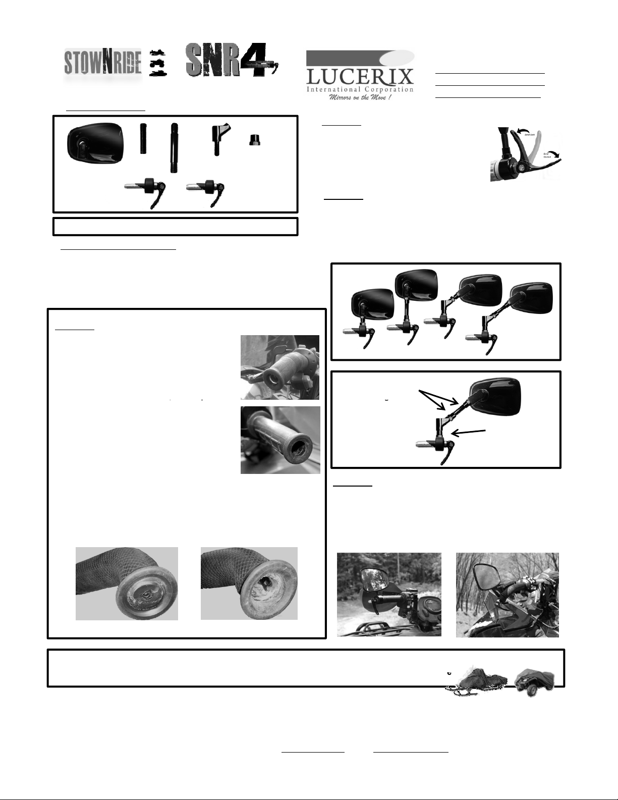
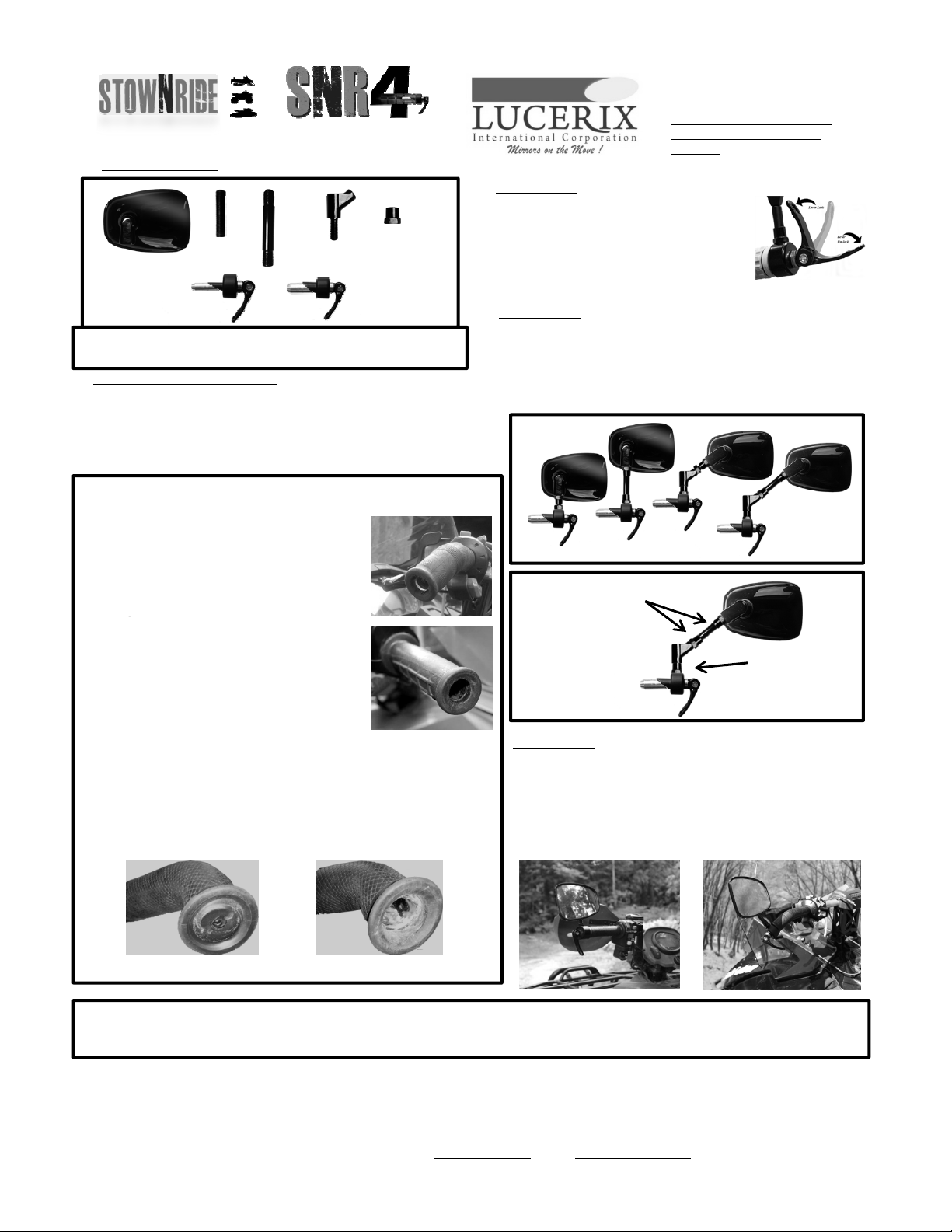
Kit Miroir CONTENU
Insérez le verrou miroir dans la barre.
Si le verrouillage du miroir ne glisse pas
librement, desserrez le verrou à l'aide du levier.
Le levier doit être dans le Positiondébloquée
pour l'installation. (Fig. 5)
12mm
CamLock(1)
17mm
CamLock(1)
Miroir (1)
Court
Tige (1)
Longue
Tige (1)
Coude(1) 10mm
Desnoisettes
OR Étape 3
Assembler le miroir
E tili t l t t t bl l i i Ch i i
X3
Outils requis pour l'installation
couteau tout usage
Clé à molette
Outil de capuchon de fin de course (Exemple: Vis à capuchon ou
Torx)
Forage et bit, (requis pour certains modèles)
n
u
san
es
composan
s
res
an
s,
assem
er
e
m
ro
r.
o
s
ssez
un design qui correspond le mieux à votre style de conduite.
Exemples (Fig 6)
À l'aide des écrous fournis, verrouiller chaquecomposant en place (Fig7)
Fig6
REMARQUE: un verrou par kit. Un diam
tre de 12 ou 17 mm bas
sur le kit
commandé
Etape 1 LH ou RH, Modify Bar
Si la poignée d'usine a un capuchon d'extrémité,
simplement enlever Le bouchon avec l'outil
approprié.
Si la
oi
née d'usine n'a
as de ca
de fin et est
Fig1
Noix deblocage
Terminé avec une extrémité en caoutchouc formée,
couper avec soin à l'aide d'un couteau.
POUR ÉVITER LES DOMMAGES AUX GRIPS
CHAUFFÉSNE PAS COUPERAU CORPSDU GRIP.
COTEZ LA FIN DE GRIP SEULEMENT!
Devrait apparaître comme indiqué (Fig 1 & 2)
Fig2
Étape 4
Assemblée finale
Fig7
Noix deblocage
Certaines barres de manutention de fabrication ont un insert ou un capuchon
d'extrémité en plastique dur (Fig. 3). Ceci doit être retiré en perçant l'insert.
(Fig. 4)
Remarque: le retrait de l'insert ou du capuchon d'extrémité n'endommage pas
les poignées chauffées.Si vous êtes Pas sûr ou capable de percer l'insert,
contactez votre revendeur
Before After
Ajustez votre miroir
l'angle de vision optimal.Verrouiller tous les
composants En place. Les écrous doivent être serrés avec une clé.
(Fig. 7) Pour verrouiller le miroir dans le tube, tournez le levier dans
le sens des aiguilles d'une montrejusqu'à ce que vous ressentez
une tension ou une résistance. Pivotez le Levier de 90 degrés pour
verrouiller (Fig.5)
Véhiculetoutterrain
Exemple de barre d'usine qui a eu le capuchon en plastique dur foré et retiré.
PAS D'OUTILS REQUIS POUR UNE UTILISATION QUOTIDIENNE. Il suffit de déverrouiller le levier pour retirer, de transférer d'une machine
'
autre ou de stocker le miroir pour la conduite ou le remorquage de tous terrains N
'
oubliez pas de toujours verrouiller l
Fig3Fig4
Motoneige
à l autre ou de stocker le miroir pour la conduite ou le remorquage de tous terrains
.
N oubliez pas de toujours verrouiller l
l'utilisation.
STOW‐N‐RIDE,estunprojetdebrevetappartenantàLucerix InternationalCorp.Pourdesdemandesderenseignementsetunserviceàlaclientèle,
veuillezappelernotrenumérosansfraisau800.295.3703.Garantiedefabricationstandardde1anpourdéfaut.100%deremplacementsousréserve
d'inspection.Ceproduitn'estpaséligibleàlagarantiepourlesdommagescausésparl'utilisationet/oulamodificationoulafalsification.Ceproduit
nepeutêtrerenvoyés'ilaétéinstalléetutilisé.Contacteznotreserviceclientèlesivousavezdesquestionssurlagarantie.
Corp
Office:
2488
Bristol
Ci
rcle, Oakville, Ont. CANADA. L6H 5S1. WWW.LUCERIX.COM. EMAIL: [email protected]. Toll free: 800.295.3703