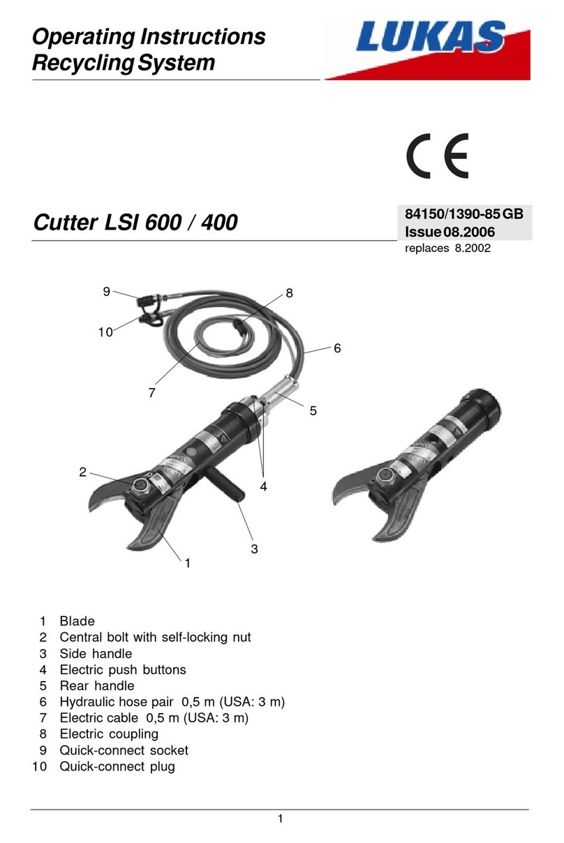
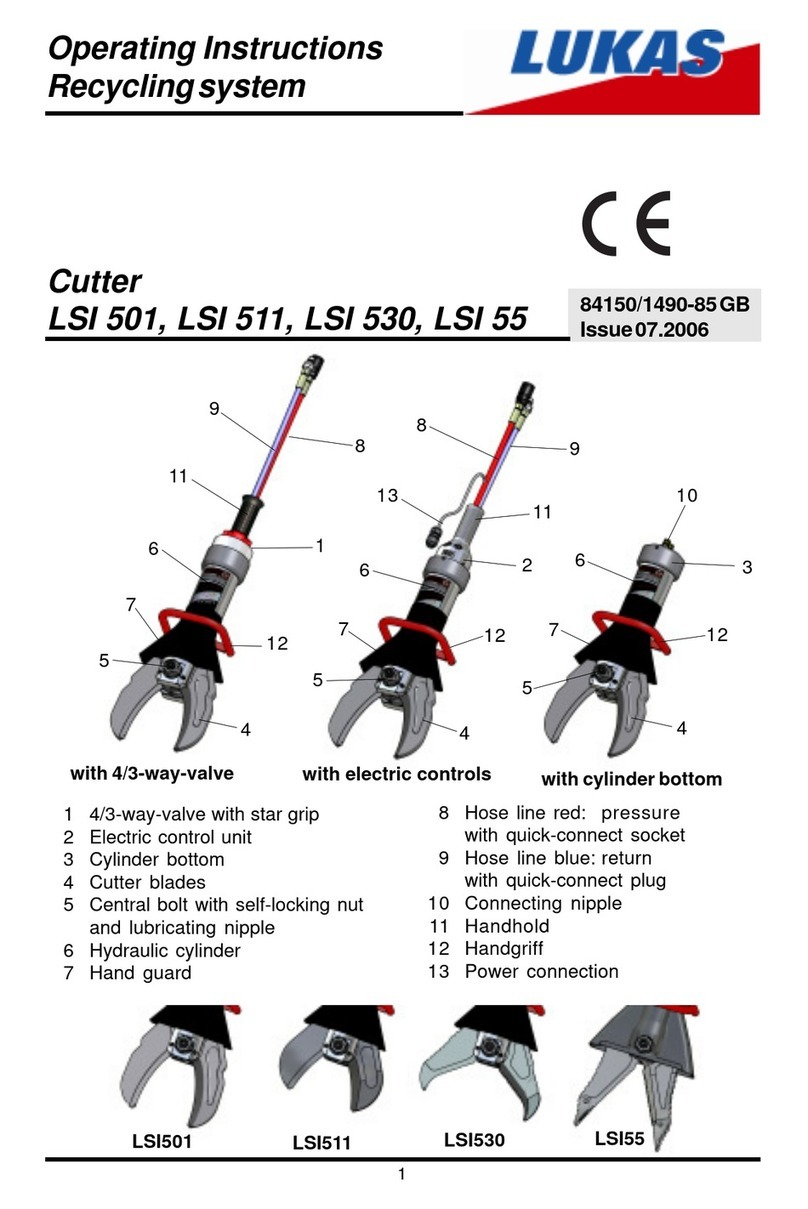
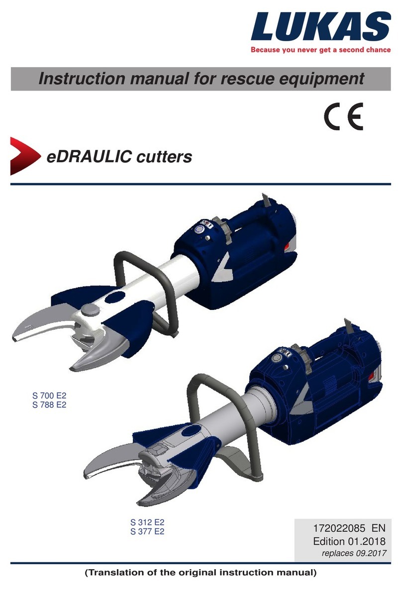
Lukas S 3 Series User manual

Cutters and combination tools
(Translation of the original operating instructions)
172047085 EN
Edition 03/2023
replaces 06/2021
Operating instructions for rescue equipment
Blade forms:
SC
S 3xx
S 7xx

2
Content Page
1. Dangerclassications 4
2. Productsafety 5
3. Properuse 8
4. Functionaldescription 9
4.1 Description 9
4.2 Equipment in detail 10
4.3 Wiring diagram 12
4.4 Operating movement controls 12
4.5 Hydraulic supply 12
4.6 Hose lines 12
5. Connectingthedevice 13
5.1 General 13
5.2 Coupling the mono-couplings 13
5.3 Coupling the plug couplings 15
6. Operation 15
6.1 Preparatory measures 15
6.2 Operating the star grip 16
7. Cutting,spreading,pullingandsqueezing 16
7.1 Safety instructions 16
7.2 Cutting 17
7.3 Spreading (combination tools only) 20
7.4 Pulling (combination tools only) 21
7.5 Squeezing (combination tools only) 22
8. Dismantlingthedevice/deactivationfollowingoperation 23
9. Maintenanceandservice 23
8.1 Cutter or combination tool 23
8.2 Hydraulic unit 23
8.3 Hose lines 23
9.1 Cutter/combination tool, overall 24
9.2 Protective equipment 24

3
10. Repairs 25
10.1 General 25
10.2 Preventative service 26
10.3 Repairs 27
11. Troubleshooting 39
12. Technicaldata 42
12.1 Cutters 42
12.2 Combination tools 50
12.3 Torque of the pivot bolt 53
12.4 Cutting capacities 54
12.5 Datasheets for product performance 55
12.6 Recommendedhydraulicuid 66
12.7 Operating and storage temperature ranges 66
13. EC/UKCAdeclarationsofconformity 67
13.1 Cutters 67
13.2 Combination tools 72
14. Notes 75
Content Page

4
Wearahelmetwithfaceprotection
Wearprotectivegloves
Wearprotectivefootwear
Properrecycling
Protecttheenvironment
Readandfollowtheinstructionmanual
Wedierentiatebetweenvariousdierentcategoriesofsafetyinstructions.Thetableshown
belowprovidesanoverviewoftheassignmentofsymbols(pictograms)andsignalwordsto
thespecicdangerandthepossibleconsequences.
1. Danger classications
Pictogram Damage/
injury to Keyword Denition Consequences
Persons
DANGER! Immediatedanger Deathor
severeinjury
WARNING!
Potentially
dangerous
situation
Potentialdeath
orseriousinjury
CAUTION! Lessdangerous
situation
Minororslight
injury
Property
ATTENTION!
Riskofdamage
toproperty/
environment
Damageto
thedevice,
damagetothe
environment,
damageto
surroundings
NOTE
Handlingtipsand
otherimportant/
usefulinformation
andadvice
Noinjury/
damageto
persons/
environment/
device

5
2. Product safety
LUKAS products are developed and manufactured to ensure the best performance and
qualitywhenusedasintended.
Thesafetyoftheoperatoristhemostimportantconsiderationinproductdesign.Furthermore,
theinstructionmanualisintendedtohelpyouuseLUKASproductssafely.
Inadditiontothesafetyinformationintheseoperatinginstructions,allgenerallyapplicable,
statutoryandotherbindingnationalandinternationalaccidentpreventionregulationsmust
beobservedandoperatorsmustbeinstructedaccordingly.
Thedevicemayonlybeoperatedbypersonswithappropriatetraininginthesafetyaspects
ofsuchequipment,otherwise,thereisariskofinjury.Allrescueteamsworkingattheplaceof
operationmustwearprotectiveclothing.Personsandpatientswithintherescueequipment’s
operationalrangemustbeprotectedbyplacingashatterguardorsuitablealternativedevice
betweentheworkingareaandtheperson.
Wewouldliketopointouttoallusers,theyshouldcarefullyread,understandandfollowall
operatinginstructionsbeforeusingtheproduct.
Wefurtherrecommendthatyouhaveaqualiedtrainershowyouhowtousetheproduct.
WARNING / CAUTION!
Theoperatinginstructionsforthehoses,accessoriesandconnecteddevices
mustalsobeobserved!
Evenifyouhavealreadyreceivedinstructionsonhowtousethedeviceyoushouldstillread
throughthefollowingsafetyinstructionsagain.
WARNING / CAUTION!
Makesurethattheaccessoriesusedandtheconnecteddevicesaresuitable
forthemax.operatingpressure!
Makesurethatnobody
partsorclothinggetscaught
betweentheopen,visibly
movingdeviceparts
(e.g.pistonclawandcylinder).
Workingundersuspended
loadsisnotpermittedwhere
suchloadsarebeinglifted
onlybymeansofhydraulicde-
vices.Ifthisworkisunavoid-
able,suitablemechanicalsup-
portsarealsorequired.
Wearprotectiveclothing,
asafetyhelmetwithvisor,
protectivefootwearand
gloves.
Inspectthedevicebeforeand
afteruseforvisibledefectsor
damage.
Immediatelyreportany
changesthatoccur
(includingchangesin
operatingbehavior)to
theappropriatepersons/
departments!Ifnecessary,
thedeviceistobeshutdown
immediatelyandsecured!
Alllines,hosesandscrew
connectionsmustbechecked
forleaksandexternally
visibledamage.Thesemust
berepairedimmediately!
Escapinghydraulicuidcan
causeinjuriesandres.

6
Intheeventofmalfunction,
immediatelydeactivatethe
deviceandsecureit.
Repairthefaultimmediately
(orhaveitrepaired).
Donotcarryoutanychanges
(additionsorconversions)to
thedevicewithoutobtaining
thepriorapprovalofLUKAS.
Observeallsafetyanddanger
informationonthedeviceand
intheinstructionmanual.
Allsafetyanddanger
instructionsonthedevice
mustalwaysbecompleteand
inalegiblecondition.
Anymodeofoperationwhich
compromisesthesafetyand/
orstabilityofthedeviceis
forbidden!
Observeallintervalsfor
recurringtestsand/or
inspectionsthatareprescribed
orstatedintheinstruction
manual.
Safetydevicesmustneverbe
disabled!
Themaximumpermissible
operatingpressuremarked
onthedevicemustnotbe
exceeded.
Beforeswitchingon/starting
upthedeviceandduringits
operation,makesurethatthis
willnotposeanydangerto
personnel.
OnlygenuineLUKAS
accessoriesandspareparts
aretobeusedforrepairs.
Pleaseensurethatyoudonot
becomeentangledinhose
loopsandtripwhenworking
withortransportingthedevice.
Whenworkingclosetolive
componentsandcables,
suitablemeasuresmust
betakentoavoidcurrent
transfersorhigh-voltage
transferstothedevice.
Pleasenotethat,when
spreadingandcutting,
tearingorbreakingcancause
materialtofall,orsudden
removalofsuchcancauseit
tosuddenlycatapulto,
andnecessaryprecautions
mustbetaken.
Thebuild-upofstaticcharges
andpossiblesparkingmust
beavoidedwhenhandlingthe
device.
Onlytouchbroken-oor
cut-opartswhilewearing
protectivegloves,asthetorn/
cutedgescanbeverysharp.

7
Inadditiontothesafetyinstructionsintheseoperatinginstructions,allgenerallyapplicable,
statutoryandotherbindingnationalandinternationalaccidentpreventionregulationsmust
beobserved,andoperatorsmustbeinstructedaccordingly.
WARNING / CAUTION / ATTENTION!
Thisdeviceisintendedexclusivelyforthepurpose described in the instruction manual
(see chapter “Proper use”).Any otheruse isnot in accordance with its proper use.
The manufacturer/supplier is not liable for any damage resulting from improper use.
Theuserbearssoleresponsibilityforsuchuse.
Properuseincludesobservanceoftheinstructionmanualandcompliancewiththeinspection
andmaintenanceconditions.
Never work in a fatigued or intoxicated state!
Thedeviceislledwith
hydraulicuid.Thishydraulic
uidcanbedetrimentalto
healthifitisswallowedorits
vaporisinhaled.Directcontact
withtheskinmustbeavoided
forthesamereason.Also,
whenhandlinghydraulicuid,
notethatitcannegatively
aectbiologicalsystems.
Whenworkingwithorstoring
thedevice,ensurethatthe
functionandthesafetyofthe
devicearenotimpairedby
theeectsofsevereexternal
temperaturesandthatthe
deviceisnotdamagedinany
way.Pleasenotethatthe
devicecanalsoheatupover
alongperiodofuse.
Whenworking,ensure
sucientlightingsothat
thecuttingprocessandthe
behaviorofthecuttingdevice
andcuttingmaterialisclearly
visible.
Beforetransportingthe
device,alwaysensurethatthe
accessoriesarepositionedin
suchawaythattheycannot
causeanaccident.
Alwayskeepthisinstruction
manualeasilyaccessibleat
theplaceofoperation.
Makesureallpartsremoved,
oilandliquidresidues,and
packagingmaterialsare
disposedofproperly!

8
3. Proper use
LUKAS“SC”combinationtoolsandLUKAS“S”cuttersaredesignedspecicallyforrescuing
andretrievingvictimsintrac,railorairaccidentsandforcarryingoutrescuesfrombuildings.
Theyareusedforfreeingpeopleinjuredinaccidentse.g.bycuttingdoors,roofbarsand
hinges.ByusingtheLUKAScombinationtools,trappedpersonscanalsobefreede.g.by
spreadingoutdoorsand/orbyremovingobstacleswiththeaidofachainset.Ingeneral,
thecombinationtoolcanbeusedtocut,pull,spread,squeezeandliftobjects.Ingeneral,
LUKAScutterscanonlybeusedtocutobjects.
Allobjectstobeworkedonmustbesecuredusingstablesupportsorsubstructures.
Sample applications of the combination tools:
Sample application of the cutters:

9
4. Functional description
You can obtain accessories and replacement parts for the rescue devices from your
authorizedLUKASdealer.
LUKAScuttersandcombinationtoolscanalsobeusedunderwateratadepthofupto40m
(131 ft).
ATTENTION!
Inthiscase,youmustpaystrictattentiontoanyleaksinordertopreventrisks
threateningtheenvironment.
WARNING / CAUTION!
Allobjectstobeworkedonmustbesecuredusingstablesupportsorsubstructures.
WARNING / CAUTION / ATTENTION!
Thefollowingmaynotbecut/squeezed:
- livecables
- preloaded and hardenedpartssuchassprings,springsteels,
steeringcolumns,bodyworkreinforcements,hingesand
xingbolts,e.g.forfasteningseatbelts
- pipesundergasorliquidpressure,
- compoundmaterials(steel/concrete)
- explosivebodiessuchasairbagcartridges
NEVERoperatetherescueequipmentatahigheroperatingpressurethanthat
stated in the chapter “Technical data”.A higher setting can cause damage to
propertyand/orleadtoinjuries.
LUKASrescueequipmentmayonlybeusedinanareaatriskofexplosionifan
explosionhasbeenpreventedbyappropriatemeasures.Youmustalsotakeinto
accountthefactthatsparksmaybecreated,forexamplewhencuttinganobject.
When working in potentially explosive atmospheres, all applicable
legal, national and international regulations, standards and
safety rules for avoiding explosions must be observed without
restriction.
4.1 Description
Theequipmentisdesignedsuchthat,viaahydraulicallyactivatedpiston,twoequal,opposite
blade arms are symmetrically opened/closed by mechanical joints, thereby spreading,
squeezing,pullingorcuttingobjects.
Allcuttersandcombinationtoolsensureafullload-holdingfunctionwhendisconnectedfrom
thehydraulicsupply(e.g.whenunintentionallydecoupled,defectivehose,etc.).

10
1 Stargrip
2 Controlvalve
3 Bodyofrescuedevice
4 Handle
5 Protectivehose/protectivecover
6 Bladearm
7 Pivotboltwithself-lockingnut
8 Handhold
9 Pressurehose
10 Returnhose
11 Mono-couplingnipple
12 Quick-disconnectcouplingnipple
13 Quick-disconnectcouplingsleeve
14 Kink-protection
Quick-disconnect coupling
system:
13
12
2
3
6
9
10
1
4
5
67
8
9
10 11
1
5
6
7
8
10
9
11
3
4.2 Equipment in detail
2
3
4
1
5
6
7
1
9
10 11
8
5
14
14
14

11
1 Stargrip
2 Controlvalve
3 Bodyofrescuedevice
4 Handle
5 Protectivehose/protectivecover
6 Bladearm
7 Pivotboltwithself-lockingnut
8 Handhold
9 Pressurehose
10 Returnhose
11 Mono-couplingnipple
12 Quick-disconnectcouplingnipple
13 Quick-disconnectcouplingsleeve
14 Kink-protection
Quick-disconnect coupling
system:
13
12
2
3
4
5
6
7
1
9
10 11
8
14
2
3
4
5
6
7
1
9
10 11
8
14

12
4.3 Wiring diagram
Tofacilitatehowthesystemfunctions,asimpliedschematicdiagram(hydrauliccylinderof
therescueequipment(A)+handvalve(B))isshownhere.
AB
cutting/closing/
pulling/squeezing
spreading/
opening
4.4 Operating movement controls
Thepistonmovementiscontrolledbythestargripontheattachedvalve.
Stargrip
Fig.3
4.5 Hydraulic supply
OnlyLUKASmotorpumpsorhandpumpsmaybeusedtodrivetheequipment.
Ifthepumpismadebyadierentmanufacturer,itmustbeensuredthatithasbeenmade
according to LUKAS’ specications, otherwise dangerous torques can result for which
LUKASisnotresponsible.Ensure inparticularthat the authorizedoperating pressure for
LUKASequipmentisnotexceeded.
NOTE:
Before using other pumps made by other manufacturers, you should contact
LUKASoranauthorizeddealer.
Thepumpunitandtherescuedeviceareconnectedbyhoses.
4.6 Hose lines

13
5. Connecting the device
5.1 General
Twoshorthosesarettedonthedeviceandconnectedtothepumpunitviaapairofhoses.
Allhoselinesareidentiedbycolorandttedwithcouplingstopreventanyconnectionerrors.
Nipple
(malecoupling)
Sleeve
(femalecoupling)
Dustcaps
The device is connected to the hydraulic pump via quick-disconnect coupling halves
(sleeveandnipple),whicheliminatesconfusion.
NOTE:
Thedevicescanbeequippedwithdierentcouplingsystems.
Theydieronlybyarticlenumberbutnotbydesignation.
Ofcourse,thecouplingsystemscanalsobemodiedatalaterstage.
5.2 Coupling the mono-couplings
WARNING / CAUTION / ATTENTION!
Priortoconnectingthe devices, ensurethat all the components being used
aresuitableforthe maximum operating pressure of the pump unit.Incaseof
doubt,youmust contact LUKASdirectly!
0
0
1

14
Before coupling, remove the dust caps, then connect the nipple and sleeve and turn
thelocking sleeveof thefemale couplingin direction“1” untilthe lockingsleeve latches.
Theconnectionisnowestablishedandsecured.Decouplingisaccomplishedbyturningthe
lockingsleeveindirection“0”.
The devices can also be coupled under pressure, provided that the connected work
equipmentisnotactivated.
NOTE:
We recommendconnectingthecouplinghalvesinadepressurisedstatewhen
working in low ambient temperatures, and using extension hose assemblies/
hose reels, as otherwise the coupling may require the application of a great
dealofforce.
Thedustcapssuppliedmustbereplacedtoprovideprotectionagainstdust.
WARNING / CAUTION / ATTENTION!
Themono-couplingsmust notbe screwed othe hoselines and/orthe hose
linesmustnotbeconfused.
Mounting the dust caps:
Thedustcaps“A”havetwointernalpins“B”.Thedustcapsmustbeplacedonthecoupling
nippleinsuchawaythatthepinsareguidedintothegrooves“C”.Screwthedustcapson
untilthelimitstopattachesthemtothecouplingnipple.
A
B
C

15
The device is connected to the hydraulic pump via quick-disconnect coupling halves
(sleeveandnipple),whicheliminateconfusion.
Beforecoupling,removedustprotectioncaps,thenpullbackandholdthelockingsleeve
ofthecouplingsleeve(positionX).Pushnippleandcouplingsleevetogetherandrelease
the locking sleeve. Finally, turn the locking sleeve to position Y. The connection is now
establishedandsecured.Uncouplingiscarriedoutinthereverseorder.
WARNING / CAUTION / ATTENTION!
Someofthequick-disconnectcouplingshavespecialfunctionsandmaytherefore
notbeunscrewedfromthehoselinesand/orinterchanged!
X
Y
Thedustcapssuppliedmustbereplacedtoprovideprotectionagainstdust.
NOTE:
Couplingthedevicesisonlypossibleifthehosesaredepressurized.
5.3 Coupling the plug couplings
ATTENTION!
Alwaysconnectthereturnlinerstandthenthesupplyline!
6.1 Preparatory measures
6. Operation
6.1.1 Commissioning
Beforeinitialoperationandafterrepairs,thedevicemustbebled:
- Connectthedevicetothehydraulicpump(seechapter“Connectingthedevice”).
- Completelyopenandclosethebladearmsoftheequipmentseveraltimeswithoutany
load(see“Operatingthestargrip”chapter).
NOTE:
We recommend that when bleeding the system, the attached power unit for
thehydraulicsupplyshouldstandonahigherlevelthanthebodyoftherescue
device.
Recommended procedure for bleeding the rescue device:
1.) Fullyopenandclose1xwiththebladearmsfacingupwards
2.) Fullyopenandclose1xwiththebladearmsfacingdownwards
3.) Fullyopenandclose1xwiththebladearmsfacingupwards
4.) Fullyopenandclose1xwiththebladearmsfacingdownwards

16
Opening the device ( ):
Turnthestargripinaclockwisedirection(inthedirectionofthe
relevantsymbol)andkeepinthisposition.
Closing the device ( ):
Turnthestargripinaclockwisedirection(inthedirectionofthe
relevantsymbol)andkeepinthisposition.
“Dead-man’s” function:
Followingrelease,thestargripautomaticallyreturnstothe
central/neutralposition,fullyguaranteeingretentionoftheload.
7. Cutting, spreading, pulling and squeezing
7.1 Safety instructions
Beforetherescueworkcancommence,thepositionoftheobjectinvolvedintheaccident
mustbestabilized.
Youmustensureanadequatesubstructureand/oradequatesupportfortheobject.
Worldwide safety guidelines pertaining to the specic country must be observed and
compliedwith.IntheFederalRepublicofGermany,regularsafetyinspectionsaccordingto
theregulations of theGesetzlichenUnfallversicherung(GUV;“Legalaccidentinsurance”)
aremandatory.
Inareasatriskofexplosion,theequipmentshouldonlybeusedifanexplosionhasbeen
preventedbyappropriatemeasures.
Thefollowingaretobewornwhenworkingwiththerescueequipment:
- protectiveclothing,
- safetyhelmetwithvisororprotectivegoggles,
- protectivegloves
- and,ifnecessary,earprotection
6.1.2 Inspecting the pump unit
Seetheseparateoperatinginstructionsfortheappropriatepowerunit
(orthehandpump).
NOTE:
Before starting up the hydraulic unit each time, make sure that the actuating
valvesaresettodepressurizedcirculation.
NOTE:
Before coupling the quick-disconnect couplings, the actuating valves of the
pumppowerunitmustbesettodepressurizedcirculation.
Ifyouusemono-couplings,youcanalsocouplewhenthehosesarepressurized.
6.2 Operating the star grip

17
Reaching between the blade arms is strictly forbidden!
WARNING / CAUTION!
Theparticularforceactionoftherescueequipmentduringoperationcouldcause
piecesofthevehicletobreakooryo,posingadangertopersons.Therefore,
thosenotinvolvedintherescueoperationshouldkeep at a distance appropriate
to the situation.Personsandpatientswithintherescueequipment’soperational
rangemustbeprotectedbyplacingashatterguardorsuitablealternativedevice
betweentheworkingareaandtheperson.
7.2 Cutting
Beforeoperatingtherescuedevice,youmustensurethatnoparticipantsorbystandersare
atriskfromthemovementsoftherescuedeviceorfromyingfragments.Avoidunnecessary
damagetopropertybelongingtoothersortoobjectsnotinvolvedintherescueordamage
causedbyyingfragments.
Thebladesshouldbepositionedata90°angletotheobjecttobecut,ifpossible.
RIGHT
WRONG
12
93
15°
15°
90°
Highercuttingcapacitiescanbeachievedbycuttingascloseaspossibletotheblade’spivot
point.
RIGHT
WRONG
WARNING / CAUTION / ATTENTION!
If the cutter twists to the side at an angle of 15° during the cutting process,
thecutmustbere-positioned,otherwisethetransverseloadonthebladewillbe
toohighandthiscoulddamagethedevice,particularlytheblades.

18
During cutting, the gap between the blade tips (in the transverse direction) must not be
exceeded,otherwisethebladeisindangerofbreaking:
ATTENTION!
Avoid cutting particularly high-strength parts of the vehicle’s bodywork
(e.g.side-impactprotection):thisalmostalwayscausesdamagetothecutter/
combinationtool.
Cutting with SC 358 and SC 758
ThespreadingtipcanberemovedfromtheSC358andSC758.Thispreventstheobject
tobecutfromgettingstuckbetweenthespreadertips,hinderingthecuttingprocess.
Cutter/combination tool max. gap at the blade tips
[mm] / [in.]
S 120 2/ 0.08
S 312
3/ 0.12
S 377
S 378
S 700
SC 358
SC 557
SC 758
S 788
5/ 0.20S 789
S 799
3.
2.
1.
A

19
Removing the tip
Step 1:
Toremovethespreadertips,rstpushoutbolt“A”alittle,withyourngeroranobject.
Afairamountofforceneedstobeappliedinitially,asthebolthasaballcatchtopreventit
fromfallingoutunintentionally.
Step 2:
Theboltcanthenbegrippedbytheangeandpulledoutuptothelimitstop.Thelimitstop
willpreventtheboltfrombeingpulledoutentirely.Thismeansthatitcannotbelost.
Step 3:
Pullthespreadertipforwardstoremoveit.
Attaching the spreader tip:
Attachmentofthespreadertiptakesplaceinthereversesequence.
Ensurethattheboltisalwayscompletelypushedinandengages.Ifthebolthas
notengaged,thismayresultinthetipinadvertentlycomingloosewhileinuse.
Thisinturncouldresultindamagetotherescueequipment.Therescuedevice
couldalsosliporpartscouldbeungo,resultingininjuriestoboththeoperator
andthecrashvictim.
Caremustalsobetakenthattheboltdoesnotinadvertentlycomeloosewhile
thedeviceisinuse.

20
Whencarryingoutspreadingandliftingwork,makesurethatthetipsareforce-ttedacross
theirfullwidth(seegurebelow).
Otherwisethereisariskthatthepartswilljumpaway.
7.3 Spreading (combination tools only)
Only use the front area of the tips to increase the gap. Full spreading capacity can be
achievedwhenapproximatelyhalfofthegroovedareaofthetipsisused.Thegreatestforce
iscreatedintherearareaofthespreadingrangeofthecombinationblade.
Workingsurfaceistoosmall,
tipsslipo.
Onlyforincreasingthesize
ofagap(notsuitablefor
spreading)
Tipsgetasafegrip.
This manual suits for next models
12
Table of contents
Other Lukas Cutter manuals
Popular Cutter manuals by other brands

Roland
Roland Stika Plus STX-8 user manual

Hitachi
Hitachi VB 13Y Technical data and service manual

Emerson
Emerson Klauke ESG 85CFM manual

Farm King
Farm King II Series Operator and parts manual

Wolfcraft
Wolfcraft TC 670 Project Translation of the original operating instructions

Thermocutters
Thermocutters AZTC20 Start-up and operation