Farm King II Series Product manual

Rotary Cutter
Series II - 5' & 6'
OPERATOR AND PARTS MANUAL
052013 FK379


3
Table of Contents - Series II Rotary Cutter
Table of Contents
Introduction .................................................................................................................................5
Safety............................................................................................................................................6
• Safety Instruction.............................................................................................................6
• General Safety..................................................................................................................7
• Start-up Safety .................................................................................................................7
• Operation Safety ..............................................................................................................7
• Transport Safety...............................................................................................................7
• Service and Maintenance Safety ....................................................................................8
• Storage Safety..................................................................................................................8
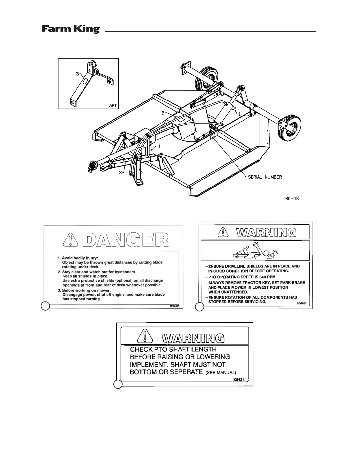
• Safety Signs .....................................................................................................................8
• Safety Sign Installation ...................................................................................................8
Assembly....................................................................................................................................10
• 3-Point Hitch Mounted Assembly Instructions ............................................................10
• Trailing Model Assembly Instructions..........................................................................10
• Chain Kit Assembly Instructions................................................................................... 11
Operation ...................................................................................................................................12
• Theory of Operations.....................................................................................................14
Maintenance ..............................................................................................................................15
• Service ............................................................................................................................15
Bolt Torque .................................................................................................................................16
• Checking BoltTorque .....................................................................................................16
Part Drawings.............................................................................................................................18
• 3-Point Hitch Mounted Drawing ...................................................................................18
• Trailing Drawing.............................................................................................................19
• Parts List .........................................................................................................................20
• Chain Kit Drawing (Optional)........................................................................................24
• Chain Kit Parts List (Optional).......................................................................................25
• 510 PTO Shaft Drawing..................................................................................................26
• 510 (Shear Pin)Trailing Parts List..................................................................................27
• 510 (Shear Pin) 3-Point Hitch Parts List ........................................................................28
• 620 & 720 PTO Shaft Drawing.......................................................................................30
• 620 (Slip Clutch) 3-Point Hitch Parts List ......................................................................31
• 620 (Slip Clutch)Trailing Parts List................................................................................32
• 36

4
• 510 Gearbox Drawing....................................................................................................34
• 510 Gearbox Parts List...................................................................................................35
• 620 Gearbox Drawing....................................................................................................36
• 620 Gearbox Parts List...................................................................................................37
• Cylinder Drawing and Parts List ...................................................................................38
Shipping Kit and Bundle Numbers ..........................................................................................39
• Optional Bundle Numbers ............................................................................................40
Warranty.....................................................................................................................................42
Manufacturer’s statement: for technical reasons Buhler Industries Inc. reserves the right to modify
machinery design and specifications provided herein without any preliminary notice.
Information provided herein is of descriptive nature. Performance quality may depend on soil fertility,
applied agricultural techniques, weather conditions and other factors.
Table of Contents - Series II Rotary Cutter

5
Introduction - Series II Rotary Cutter
Introduction
The Farm King Series II Rotary Cutter is available in widths of 60", 72" and 84" and can be equipped
with either trailing style or 3-point hitch.The 3-point hitch is Quick Hitch compatible so it is easy to
attach and unhook. 3-point hitch models include a single solid rubber trailing wheel, while rotary
cutters with a trailing hitch have two wheels, either air-filled or made of solid rubber.
Farm King Rotary Cutters are built tough and made to last.The blades are heat-treated to enhance
rigidity and the heavy-duty gearbox is designed to be rugged and durable.The access panel on the
deck makes it easy to inspect or replace the blades. An optional chain kit minimizes the possibility
of flying debris.The stump-jumper is a 24" plate mounted to the blades below the gearbox and
minimizes stress on the deck and gearbox.The power take-off (PTO) shaft on the series II 60" rotary
cutter includes a shear pin to protect the gearbox in the event of an unforeseen obstacle, while
the 72" and 84" rotary cutters are equipped with a slip clutch to prevent gearbox damage.The 72"
with the trailing style hitch (Y720T) includes a two-piece PTO shaft for tighter turning radius. An 8"
cylinder and hoses are optional for all trailing models.
Keep this manual handy for frequent reference. All new operators or owners must review the
manual before using the equipment and at least annually thereafter. Contact your Farm King
Dealer if you need assistance, information, or additional copies of the manual. Visit our website
at www.buhlerindustries.com for a complete list of dealers in your area.
The directions left, right, front and rear, as mentioned throughout this manual, are as seen facing
in the direction of travel of the implement.

6
Safety - Series II Rotary Cutter
Safety
Safety Instructions
Remember,YOU are the key to safety. Good safety practices not only protect you, but also the
people around you. Make these practices a working part of your safety program. Be certain that
everyone operating this equipment is familiar with the recommended operating and maintenance
procedures and follows all the safety precautions. Most accidents can be prevented. Do not risk
injury or death by ignoring good safety practices.
The alert symbol is used throughout this manual. It indicates attention is required and identifies
hazards. Follow the recommended precautions.
The safety alert symbol means…
ATTENTION! BECOME ALERT!YOUR SAFETY IS INVOLVED!
CAUTION The caution symbol indicates a potentially hazardous situation
that, if not avoided, may result in minor or moderate injury. It
may also be used to alert against unsafe practices.
WARNING
The Warning Symbol indicates a potentially hazardous situation
that, if not avoided, could result in death or serious injury, and
includes hazards that are exposed when guards are removed. It
may also be used to alert against unsafe practices.
DANGER
The Danger Symbol indicates an imminently hazardous situation
that, if not avoided will result in death or serious injury. This
signal word is to be limited to the most extreme situations,
typically for machine components that, for functional purposes,
cannot be guarded.

7
Safety - Series II Rotary Cutter
General Safety Instructions
• Have a first-aid kit available for use and know how to use it.
• Have a fire extinguisher available, stored in a highly visible location, and know how to use it.
• Wear appropriate protective gear.This list may include but is not limited to:
- hard hat
- protective shoes with slip resistant soles
- protective glasses or goggles
- heavy gloves
- wet weather gear
- hearing protection
- respirator or filter mask
• Read and understand the Operator’s Manual and all safety signs before operating, servicing,
adjusting, repairing, or unplugging the equipment.
• Do not attempt any unauthorized modifications to your Farm King product as this could affect
function or safety, and could affect the life of the equipment.
• Never start or operate the mower except from the operator’s station on the power unit.
• Inspect and clean the working area before operating.
• Keep hands, feet, clothing, and hair away from moving parts.
• Ensure bystanders are clear of the area before operating.
Start-up Safety
• Do not let inexperienced operators or children run this equipment.
• Place all tractor and machine controls in neutral before starting.
• Operate only with ROPS and seatbelt equipped tractors.
• Do not operate inside a building unless there is adequate ventilation.
• Ensure all shields are in place and in good condition before operating.
• Stay clear of PTO shaft and machine when engaging PTO.
Operation Safety
• Do not permit riders.
• Do not wear loose fitting clothing during operation.
• Never operate over 540 PTO rpm speed.
• Never operate the equipment in the raised position.
Transport Safety
• ReviewTransport Safety instructions in tractor manual before moving.
• Check with local authorities regarding transport on public roads. Obey all applicable laws and
regulations.
• Do not tow equipment that does not have brakes at speeds over 20 mph (32 km/h).
• Do not tow equipment that does not have brakes that, when fully loaded, has a mass (weight)
over 3,300 lb (1,497 kg) and more than 1.5 times the mass (weight) of the towing unit.
• Make sure the SMV (Slow Moving Vehicle) emblem and all the lights and reflectors that are
required by the local highway and transport authorities are in place, are clean, and can be
seen clearly by all overtaking and oncoming traffic.

8
Safety - Series II Rotary Cutter
• Never have the equipment in operation during transport.
• Always travel at a safe speed.
Service and Maintenance Safety
• Stop engine, set brake, remove ignition key, and wait for all moving parts to stop before
servicing, adjusting, repairing, or unplugging.
• Support the equipment with blocks or safety stands before working beneath it.
• Follow good shop practices including:
- keep service area clean and dry
- be sure electrical outlets and tools are properly grounded
- use adequate light for the job.
• Replace and secure all shields removed during servicing before operating.
• Use heavy leather gloves to handle sharp objects.
• Check hydraulics regularly for leaks. Use cardboard to look for leaks, and use hand and eye
protection.
• Relieve pressure on hydraulic system before repairing or adjusting.
Storage Safety
• Store the unit in an area away from human activity.
• Do not permit children to play on or around the stored machine.
• Support the frame on stands and blocks to provide a secure base.
Safety Signs
• The following illustration shows the approximate location and detail of safety signs.
• Keep all safety signs clean and legible and replace any that are damaged or missing.
• When original parts are replaced, any safety signs affixed to those parts should be replaced
as well. Replacement safety signs are available from your local dealer.
Installation
• To install safety signs, ensure the installation area is clean and dry. Decide on the exact
position before you remove the backing paper. Remove the smallest portion of the split
backing paper and align over the specified area. Carefully press in place.
• Slowly peel back the remaining paper and smooth the remaining portion in place. Small
air pockets can be pierced with a pin and smoothed out.
• Replace safety sign immediately should it become damaged, torn or illegible. Obtain
replacements from your authorized dealer using the part numbers shown.

9
Safety - Series II Rotary Cutter
3
12

10
Assembly Instructions
3-Point Hitch Mounted Assembly Instructions
1. Mount the hitch assembly (906389/906390) to the deck using the category 1 lift arm pins
(965809/965926) supplied.The bushings (906416/906418) and the 1" I.D. washer (967140 &
907309) should allow the hitch to swivel freely.
2. The ends of the two pivot arms (906380 & 906381) with the offset holes bolt to the hitch using
a 5/8" x 4" bolt and lock nut.The offset should be turned down.The lift arm (906424/906425)
bolts between the ends of the pivot arms and the brackets at the top of the center mount
(816335/816332) using 5/8" x 2" hex bolts and lock nuts. Do not over tighten the lock nuts.The
entire hitch assembly should swivel freely if properly assembled. Assemble chain PTO holder
(909703) to 3-point hitch (906389/906390) using one 3/8" x 1-1/2" hex bolt (86171), lock washer
and hex nut.
3. Bolt the tailwheel arms (816505/815971) to the main body using 5/8" hardware. Assemble the
tailwheel adjustment weldment (816510/815977) to both the body and tailwheel arms using
5/8" x 1-3/4" bolt and hardware.This holds the tailwheel in place and sets the cutting height of
the cutter. Mount 15" wheel (814432) to tailwheel arms using washer and cotter pin (81210 &
967110).
4. Connect the PTO shaft to the gearbox. A snap ring holds on the PTO shafts with a shear pin.
The clutch must be engaged on PTO shafts with a slip clutch as per operating instructions
so the clutch will slip if you hit a hard object. After engaging clutch, bolt the PTO guard
(966502/966102) to the center mount using 5/16" x 3/4" hex bolts, lock washers and hex nuts.
5. Re-check all the fasteners.There should be free movement of all pieces held together by a bolt
and lock nut.
Trailing Model Assembly Instructions
1. Mount the swivel tube assembly (966584/966146) to the cutter deck by bolting to the outside
edge of the deck reinforcement using 1/2" x 1-3/4" hex bolts, lock washers and hex nuts.
2. The wheel yoke (F9434) may be assembled to cutter in two ways:
- Wheels trailing behind mower. Assemble as shown in drawing. Bolt the yoke arms (901051)
to the tube assembly using 1/2" x 2" hex bolts, lock washers and hex nuts with the wheels
turned to the inside of the mower. With the wheels in this position, the control rod clevis
(966525/902341) attaches to the top bracket on the tube assembly as shown in drawing.
Use a 1" I.D. flat washer and a 1/4" x 1-1/2" cotter pin to mount the wheels.
- Wheels forward at side of cutter. Bolt the yoke arms to the tube assembly so the wheels
are on the outside of the cutter. With the wheels in this position, the control rod clevis
(966525/902341) attaches to the bottom bracket on the tube assembly.
3. Bolt the tongue assembly (906414/906415) to the cutter deck using 7/8" x 2-1/2" bolts, lock
washers and hex nuts.The 1-1/4" diameter x 5/8" long bushings (966528/906418) held in place
by a 1" I.D. flat washer (967140/907309) should allow the tongue to swivel.
Assembly - Series II Rotary Cutter

11
4. Bolt the welded end of the level control rod (966526/906122) to the front tongue as shown
on drawing using a 5/8" x 2-1/2" hex bolt and lock nut.The control rod clevis (966525/902341)
must be adjusted so the cutter will sit level with the ground when it is pinned to the swivel
assembly. NOTE: Be sure to use the top bracket on the swivel assembly (966584/966146) when
the wheels are trailing behind the cutter as shown in drawing.
5. Mount the slip clutch PTO shaft on the cutter.The clutch must be engaged so it will slip when
you hit a hard object as per operating instructions. After engaging the clutch, bolt on the PTO
guard (966502/966102) using 5/16" x 3/4" hex bolts, lock washers and hex nuts.
6. An optional jack (960327) is available to lift the tongue when mounting the cutter a tractor.
7. Recheck and tighten all bolts. Only pieces held by a bolt and lock nut should have free
movement.
Chain Kit Assembly Instructions
All cutters have the required holes for mounting the chain kit.The use of this chain kit will help
reduce the possibility of injury to persons or property by stopping many thrown objects.
1. Bolt the front chain holder (966586/966147) to the front of the cutter using 1/2" x 1" hex bolts,
lock washers and hex nuts.
2. Use 1/4" x 6 link chains (966591) at the front. A chain is pushed through each slot from
underneath and a 3/8" rod is threaded through the top link of each chain. Hold rods in place
using the cotter pins supplied. See parts list for correct length of rods.
3. Bolt the rear center (966588/966149) and rear side (966593/966594) chain holder to the rear of
the cutter. Use 1/4" x 5 link chains (966596) along all rear edges.Thread rods as in front using
lengths as shown in parts list. NOTE: Washers are used to hold an extra chain at both ends of
the rear center rod and at the inside end only of the rear side rods.These extra chains close the
gap left at the corners where the chain holders meet.
Assembly - Series II Rotary Cutter

12
Operation Instructions
1. Connecting toTractor: All cutters are supplied with a standard 1-3/8" 6-spline yoke on the PTO
shaft.
WARNING
This cutter is designed to operate only with a 540 rpm PTO. After
connecting cutter to tractor and before doing any cutting, check
to see that the PTO shaft is not touching anywhere on the cutter
when raising and lowering or when cornering.
2. PTO Shafts: Make sure the length of the PTO shaft is compatible with different working
positions of the cutter. Carefully follow the lubrication chart supplied with the PTO shaft. When
cutting, avoid joint angles over 35o. PTO shafts should be disengaged when turning sharp
corners. Using tape or a bright colored marking pen, mark on the outer shields the position
where the shaft is completely pushed together and the position where you have a 4" overlap.
Watch these marks when moving the cutter through all possible operating angles to see that
the PTO shaft stays within this range.
PTO Shafts with Shear Pin: Loosen the outer shield on the implement end of the PTO and push
the gearbox shaft through the end yoke. Using snap ring pliers, put the snap ring on the end
of the gearbox shaft.This is what keeps the PTO shaft on if the shear pin breaks and the cutter
should not be used without it. Insert a 1⁄2" x 3-1⁄2" Grade 2 bolt with a lock nut to act as shear
pin and replace all shields.
PTO Shafts with Slip Clutch: NOTE: All PTO shafts with a slip clutch are shipped with the slip
clutch disengaged.There are four socket set screws on the inside of the clutch assembly which
are all turned out as far as they go to engage the clutch. Disengage by turning set screws in
fully.The clutch should slip if a hard object such as a stump or rock is hit by the blades.
WARNING Always be certain that the PTO shaft is disengaged and the tractor
brakes are locked before making this or any other adjustment.
The clutch plates should be “burned” just before using the cutter in spring for the first time.This is
done by disengaging the clutch and then engaging the PTO shaft for a few seconds till the clutch
plates smoke. After this you engage the clutch again as described above.This is done because the
plates may lock up during prolonged storage.
3. OperatingTractor Engine: Operate the tractor PTO at 540 rpm when doing normal cutting. If the
forward speed is too high, a lower gear can be used.
Operation - Series II Rotary Cutter

13
Operation - Series II Rotary Cutter
4. Cutting:The cutter should be run with the front end a little low or just level for normal light
cutting. For brush or dense tall weeds, running front end high may give a better shredding
job. On rough ground, the front end will also tend to dig in less.The cutter can also be used to
shred stubble or top vegetables prior to harvest.
5. 5' & 6'Trailing Models:The wheels supplied with the cutter are for towing at speeds of no more
than 32 km/h (20 mph).These wheels should be greased every time you use the cutter.

14
Operation - Series II Rotary Cutter
Theory of Operations

15
Maintenance - Series II Rotary Cutter
Maintenance
Service
1. Gearbox:The gearbox should be filled with SAE90 oil to the bottom edge of the lower oil plug
when shipped. Check this before using the cutter and at regular intervals to see that this oil
level is maintained.
2. Grease wheels, tail wheel spindle sleeve, universal joints and shield bushings on the PTO shaft
after every eight hours of use. Lubricate the telescoping PTO tube and the PTO quick release
about every twenty hours of use.
3. Shielding: Always keep all shielding in place and repair or replace if damaged.
4. Blades: When replacing or grinding the cutting blades, both blades must be replaced or
reground at the same time to maintain the proper balance in the cutting unit. NOTE: Use Farm
King replacement blades only. Using substitute blades may be dangerous. When changing
blades, open the access door on the deck and take the screws out of the blade pin clips.The
clips are then pulled out and the blade should fall down. Replacing the new or sharpened
blades is done with the back of the mower raised and securely blocked so it will not fall. Bolt
on the blade pin clips and close the access door.
5. PTO Shaft:To replace clutch lining on slip clutch PTO shafts, first disengage the clutch by
turning the four set screws all the way in. Remove outside bolts from clutch assembly and
replace clutch linings. When re-tightening bolts, stop when the clutch spacer starts to touch the
clutch plates.You should be able to just move the spacer by hand when you have the correct
bolt torque. Re-engage clutch after assembly is complete.

16
BoltTorque - Series II Rotary Cutter
BoltTorque
Checking Bolt Torque
The tables shown below give correct torque values for various bolts and hex bolts.Tighten all bolts
to the torques specified in chart unless otherwise noted. Check tightness of bolts periodically, using
bolt torque chart as a guide. Replace hardware with the same strength bolt.
Bolt Torque*
Bolt Diameter Grade 2 Bolts Grade 5 Bolts Grade 8 Bolts
(inches) SAE 2 SAE 5 SAE 8
“A” (lb-ft) (N.m) (lb-ft) (N.m) (lb-ft) (N.m)
0.25 (1/4) 6 8 9 12 12 17
0.313 (5/16) 10 13 19 25 27 36
0.375 (3/8) 20 27 33 45 45 63
0.438 (7/16) 30 42 53 72 75 100
0.5 (1/2) 45 61 80 110 115 155
0.563 (9/16) 70 95 115 155 165 220
0.625 (5/8) 95 128 160 215 220 305
.75 (3/4) 165 225 290 390 400 540
0.875 (7/8) 170 230 420 570 650 880
1 225 345 630 850 970 1320
Torque figures indicated above are valid for non-greased or non-oiled threads and heads unless otherwise
specified.Therefore, do not grease or oil bolts or hex bolts unless otherwise specified in this manual. When
using locking elements, increase torque values by 5%.
*Torque value for bolts and hex bolts are identified by their head markings.


18
Parts - Series II Rotary Cutter
3-Point Hitch Mounted Drawing
35
1
48
1
13
1
22
2
6
16
6
16
4
8
4
8
6
16
6
16
21
3
21
3
6
16
6
16
4
8
12
1
54
1
55
1
56
1
16
1
43
1
45
1
44
1
46
1
53
1
12
1
52
1
15
1
18
1
17
1
8
4
10
6
9
6
10
1
9
1
2
1
49
2
6
16
6
16
4
8
5
1
4
8
6
16
6
16
49
2
4
8
6
16
6
16
24
1
25
1
28
1
51
1
30
1
11
1
12
1
23
1
39
1
41
3
40
2
27
2
40
2
40
2
41
3
29
1
19
1
20
1
22
1
14
1
36
1
37
1
38
1
31
1
26
1
50
1
42
1
32
1
33
1
34
1
1
1
47
1
3
1
97
1
98
1

19
Parts - Series II Rotary Cutter
Trailing Drawing
51
1
94
1
96
1
93
1
92
1
73
2
70
2
75
2
84
2
83
2
50
1
71
1
74
272
1
53
4
12
4
11
4
53
1
12
1
95
1
81
2
7
4
18
8
17
8
58
2
86
1
89
1
85
1
88
1
87
1
90
1
57
2
59
4
59
4
66
4
18
8
17
8
91
2
60
1
65
1
4
1
96
2
99
2
80
2

20
When Ordering Parts
Always give your dealer the Model, Color and Serial Number of your machine to assist him in
ordering and obtaining the correct parts. Use the exploded view and tabular listing of the area of
interest to exactly identify the required part.
Item Part Number Description Qty
1 116786 Spacer 1.26Id,Tailwheel Rc 1
2 812026 5/16" x 1" Hex Bolt (Pl) 2
3 81210 Cotter Pin 1
4 812482 Nut Lock (Steel) 0.625Nc Grb Pl 8
5 812493 Bolt Hex 5/8" x 2-1/2" Unc 1
6 812639 Washer 0.625 Sae Flat Bs Pl 16
7 81624 1/2" x 2-1/4" Hex Bolt (Pl) 4
8 81549 Bolt Hex 0.313Nc x 0.75 Gr5pl 4
9 81568 5/16" Hex Nut Pl 6
10 81569 5/16" Lock Washer Pl 6
11 81592 3/8" Hex Nut Pl 1
12 81593 Lock Washer 0.375 1
13 816505 5' RcTailwheel Weldt 1
815971 6' RcTailwheel Weldt 1
14 816510 Tailwheel Adj Weldt - 5' 1
815977 Tailwheel Adj Weldt - 6' 1
15 81620 Bolt Hex 0.500Nc x 1.25 Gr5 Pl 6
16 816335 Center Mount - 5' 1
816332 Center Mount - 6' 1
17 81636 1/2" Hex Nut Pl 6
18 81637 0.50 Lock Washer 6
19 81676 5/8" Hex Nut - 5' 4
81700 3/4" Hex Nut - 6' 4
20 81677 Washer Lock 0.625 Pl - 5' 4
81701 3/4" Lock Washer - 6' 4
21 84270 Bolt Hex 0.625 x 1.75 Gr5 Pl 3
22 981664 Hex Bolt 5/8 x 2.25 2
23 86171 Bolt Hex 0.375 Nc x 1.25 1
24 906380 Pivot Arm - R 1
25 906381 Pivot Arm - L 1
26 906389 Hitch Weldt - 5' 1
906390 Hitch Weldt - 6' 1
27 906416 Hitch Bushing 1.25Od x 0.44Lg - 5' 2
906418 Hitch Bushing 1.50Od x 0.56Lg - 6' 2
28 906424 Lift Arm - 5' 1
906425 Lift Arm - 6' 1
29 907475 Manual Holder Assy 1
Parts - Series II Rotary Cutter
Table of contents
Other Farm King Cutter manuals