manuals.online logo
Brands
  1. Home
  2. •
  3. Brands
  4. •
  5. WilTec
  6. •
  7. Cutter
  8. •
  9. WilTec 61856 User manual

WilTec 61856 User manual

Operation Manual
360° Metal Sheet Bending Machine
61856
Illustration similar, may vary depending on model
Read and follow the operating instructions and safety information before using for the first time.
Technical changes reserved!
Due to further developments, illustrations, functioning steps and technical data can differ insignificant-
ly.
Updating the documentation
If you have suggestions for improvement or have found any irregularities, please contact us.
© by WilTec Wildanger Technik GmbH Item 61856 Page 2
http://www.WilTec.de
http://www.aoyue.eu 11 2021-1
http://www.teichtip.de
The information contained in this document may alter at any time without previous notice. It is prohibit-
ed to copy or spread any parts of this document in any way without prior written allowance. All rights
reserved.
The WilTec Wildanger Technik GmbH cannot be held accountable for any possible mistakes in this
operating manual, nor in the diagrams and figures shown.
Even though, the WilTec Wildanger Technik GmbH has undergone biggest possible efforts to ensure
that the operating manual is complete, faultless and up to date, mistakes cannot be entirely avoided.
If you should find a mistake or wish to make a suggestion for improvement, we look forward to hearing
from you.
Send an e-mail to:
[email protected]
or use our contact form:
https://www.wiltec.de/contacts/
The most recent version of this manual in various languages can be found in our online shop via:
https://www.wiltec.de/docsearch
Our postal address is:
WilTec Wildanger Technik GmbH
Königsbenden 12
52249 Eschweiler
Germany
Do you wish to pick goods up? Our pick-up address is:
WilTec Wildanger Technik GmbH
Königsbenden 28
52249 Eschweiler
Germany
To shorten the waiting time and allow for a rapid on-site transaction, we ask you to call us previously
or placing your order via the webshop.
E-mail: service@wiltec.info
Tel:+49 2403 55592-0
Fax: +49 2403 55592-15
To return orders for exchange, repair or for other purposes, please use the following address. Atten-
tion! To allow for a smooth execution of your complaint or return, it is important to contact our custom-
er service team before returning the goods.
Returns Department
WilTec Wildanger Technik GmbH
Königsbenden 28
52249 Eschweiler
E-mail: [email protected]o
Tel:+49 2403 55592-0
Fax: +49 2403 55592-15
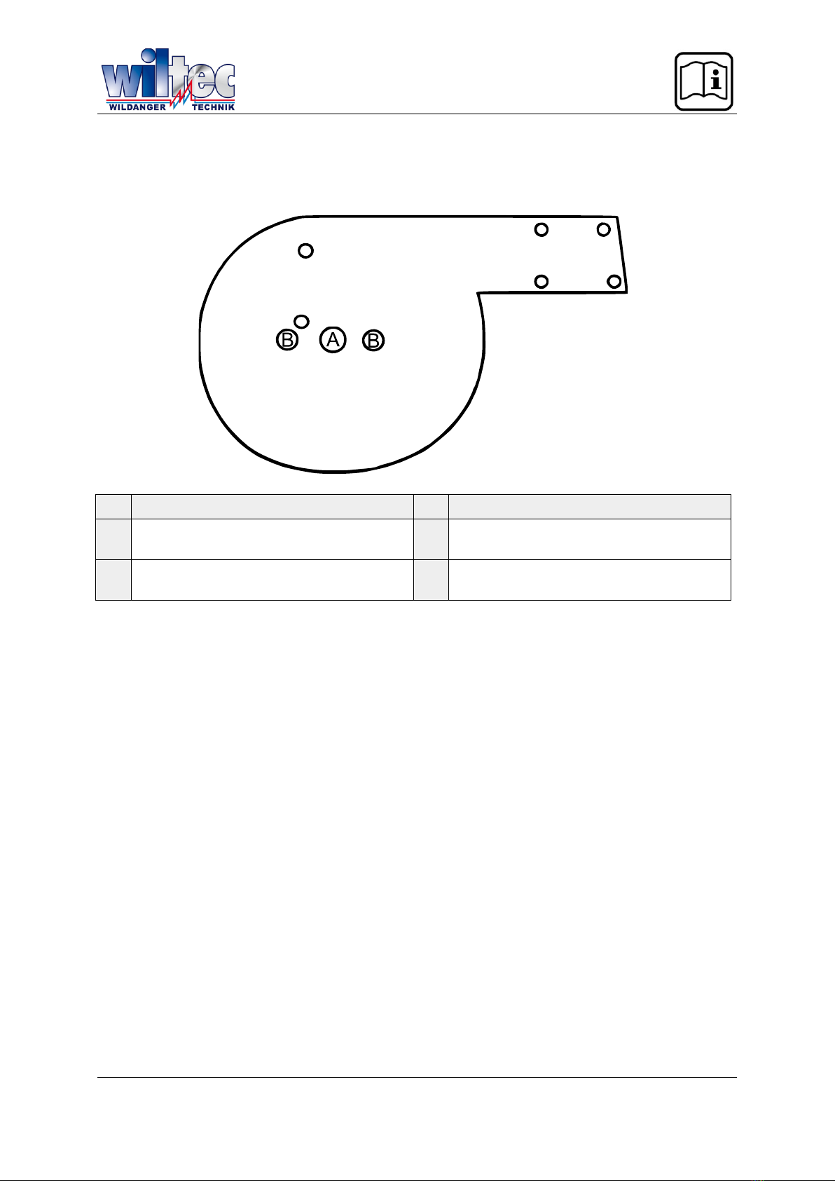
© by WilTec Wildanger Technik GmbH Item 61856 Page 3
http://www.WilTec.de
http://www.aoyue.eu 11 2021-1
http://www.teichtip.de
Introduction
Thank you for purchasing this quality product. To minimize the risk of injury we urge that our cli-
ents take some basic safety precautions when using this device. Please read the operation
instructions carefully and make sure you have understood its content.
Keep these operation instructions safe.
Safety instructions
•Check the delivery for completeness and intactness. Should pieces be missing or defective,
the tool must not be used.
•Always wear suitable protective equipment (protective gloves, work shoes, safety
goggles, etc.). Normal spectacles are not protective goggles.
•Wear appropriate clothes. Do not wear loose clothing or jewellery, tie long hair together. Oth-
erwise, they could get caught up in the rotating parts, which leads to injuries.
•Wear non-slip shoes. Make sure to have a secure stance and always keep your balance.
•Keep your work area clean and provide sufficient lighting. Untidy or badly lit work areas in-
crease the risk of accidents. Do not use the tool in wet or damp areas and do not expose it to
rain.
•Keep children and by-standers away from your work area.
•Store tools that are not in use in a dry place to prevent rust from forming. Make sure that it is

•Maintain tool with care. Make sure that tools stay sharp and tidy to obtain the best and the
safest performance. Obey the instructions for lubricating the tools and replacing the accesso-
ries.
•Make sure that the handles are and stay dry, tidy, oil-free and lubricant-free.
•Appropriately secure workpieces while working on them and make sure that you are able to
control them during the entire process. Use clamps or a vice to secure a workpiece.
•Do not bend over too far. Make sure to always have a secure stand and to be able to keep
your balance. Do not reach over or through an operating machine.
•Keep all parts of your body away from rotating parts. Risk of injuries!
•Do not apply force on tools. It will do a better and safer work if used within the performance
range that it is intended for.
•Use the right tool for your work. Do not use any tool or accessory for a work that it has not
been designed for.
•Only use accessories recommended. Using inappropriate accessories increases the risk of in-
juries.
•Before each use, check the tool for damages. The protection devices and the accessories
should be checked, too, to know if they work correctly and can be used as intended. Check
the alignment of movable parts, find broken parts, check the assembly and all conditions that
could impair the use. Protection devices or parts damaged should be repaired correctly or re-
placed.
•Do not use the tool if under the influence of alcohol, drugs or medicine, that alter your con-
sciousness.
•Never stand on the tool. Should the tool tilt over, serious injuries or damages might follow.
© by WilTec Wildanger Technik GmbH Item 61856 Page 4
http://www.WilTec.de
http://www.aoyue.eu 11 2021-1
http://www.teichtip.de
Technical specifications
Material
Cast iron
Max. bend strength (tcm²)
4.42 (28½ tin²)
Bend angle (°)
0360
Weight (kg)
23
Material of working piece
Steel, iron
Wrought iron
Brass, copper
Aluminium
Max. capaci-
ties
flat (㎜)
30×8
(1316516)
30×6
(1316)
30×8
(1316516)
30×10
(13163132)
round (㎜)
16 (58)
12 (1532)
16 (58)
18 (2332)
squared (㎜)
13×13
()
10×10
(13321332)
12×12
(15321532)
15×15
(19321932)
Operation
General
•Your tool is capable of many different types of bending operations. Materials that can be bent
include steel, iron, brass, wrought iron, and aluminium.
•To determine how to properly set up the tool, you must first determine what type of bend you
want to perform. Round shapes, angles, or spiral operations are each described in the follow-
ing sections. The numbers in brackets refer to the reference number in the exploded view of
the parts.
•-
erations. This assumes that you overbend the material to a certain extent to achieve the de-
sired degree of bending. Different materials have different degrees of spring-back. Perform a
-
Note! The bending machine must be fixed on a safe surface before being used.
Bending round forms
1. Make sure that the mounting plate for dies (4) is attached to the mounting plate of spring-
forming die (32) of the device. See Fig. 1 to know the positions required for bending round
forms.
2. Make sure that the stop (2) is loose.
3. Move the vice unit (5–9, 15) on the mounting plate holder all the way to the end.
4. Screw the mounting shaft of round-bending die (28) on the mounting plate.
5. Set the round-bending die (29) on the mounting shaft.
6. Move the bending block assembly (16, 17, 22–24) to the very end. You might have to loosen
the bending block locking plate (21) by loosening the hexagon screws (20). Do not secure the
locking plate at this moment.
7. Set the stop against the round-bending die and close the vice so that it clamps the workpiece
against the die.
8. Move the bending block until it touches the workpiece and until its front plate (16) is flush with
the vice surface (8). Secure the bending block by tightening the two screws.
9. Move the bending block to the left using the handle (27) until reaching the desired bending
-
10. Should you wish to repeat bends at the same angle, firmly tighten the stop at the spot where
you have finished the bending operation.
© by WilTec Wildanger Technik GmbH Item 61856 Page 5
http://www.WilTec.de
http://www.aoyue.eu 11 2021-1
http://www.teichtip.de
11. Should you wish to form an entire 360° ring, make sure to clamp the end of your workpiece
between the vice and die. Entirely bend your workpiece around and cut off the overspill.
12. To form springs, loosen the stop (2) and slightly lift the piece to be formed while bending it
around the die. When beginning and finishing the spring, form an entire 360° ring as described
in step 11.
Figure 1: Position of holes for fixing the dies. Darker holes have a thread.
№
Description
№
Description
A
Insert the mounting shaft of round-bending
die here.
C
Insert the die springs of angle-bending die
here.
B
Insert the hexagon screws here.
D
Insert the hexagon screw of angle-bending
die here.
Bending angles
1. Make sure that the mounting plate for dies (4) is attached to the mounting plate of spring-
forming die (32) of the device. See Fig. 1 to know the positions required for bending round
forms.
2. Make sure that the stop (2) is loose.
3. Move the vice unit (5–9, 15) to the first position on the mounting plate arm.
4. Insert the spring pin (19) of the angle-bending die (13) into the little hole without thread of the
mounting plate.
5. Attach the angle-bending die by screwing the hexagon screw (18) into the little threaded hole
of the mounting plate.
6. Move the bending block unit (16, 17, 22–24) all the way back. You might have to loosen the
bending block locking plate (21) by loosening the two hexagon screws (20). Do not secure the
locking plate at this moment.
7. Set the stop against the angle-bending die and close the vice so that it clamps the workpiece
against the die.
8. Move the bending block until it touches the workpiece and until its front plate (16) is flush with
the vice surface (8). Secure the bending block by tightening the two screws.
9. Move the bending block to the left using the handle (27) until reaching the desired bending
ang-
10. To repeat 90° angle bends, use the angle gauge assembly (10–12). Screw the shaft of the
angle gauge assembly (11)into the die. Slide the stop of the angle gauge assembly (10)onto
the shaft to the desired position (depending on the length of your workpiece). Thus, the bend-
ing 
11. Should you wish to repeat bends at another angle, use the stop (2).






© by WilTec Wildanger Technik GmbH Item 61856 Page 6
http://www.WilTec.de
http://www.aoyue.eu 11 2021-1
http://www.teichtip.de
Bending springs
1. Remove the mounting plate for dies (4) by removing the two hexagon screws. Loosen the
stop (2).
2. Pull the bending block unit (16, 17, 22–24) all the way back. Remove the front plate of the
bending block (16) by unscrewing the corresponding hexagon screw (17). Thus, the swivel
joint (22) of the bending blocks is exposed.
For steps 3, 4 and 8 see Figure 2
3. Attach the spring-forming mounting die (32) with two hexagon screws (in position 1).
4. Set the spring pin (25) of the spring- (31) in hole 3 and attach the long hexagon
screw (26)in position 2.
For steps 5 and 7 see Figure 3
5. Set the piece to be bent  (31).
6. Move the bending block unit forward until it touches the workpiece, and secure it in that posi-
tion.
7. Bend the workpiece until the piece to be 
ure).
8. Now set the spring pins (25) of the spring- (30) into the holes 4 and 5.
9. Finish bending by completely bending the piece around the dies.
Figure 2
Figure 3
© by WilTec Wildanger Technik GmbH Item 61856 Page 7
http://www.WilTec.de
http://www.aoyue.eu 11 2021-1
http://www.teichtip.de
Exploded view and parts list
© by WilTec Wildanger Technik GmbH Item 61856 Page 8
http://www.WilTec.de
http://www.aoyue.eu 11 2021-1
http://www.teichtip.de
№
Description
Qty.
№
Description
Qty.
1
Base
1
17
Hexagon screw
1
2
Stop
1
18
Hexagon screw
1
3
Body
1
19
Spring pin
1
4
Mounting plate for dies
1
20
Hexagon screw
2
5
Vice drive screw
1
21
Bending block locking plate
1
6
Vice handle
1
22
Bending block swivel joint
1
7
Vice base
1
23
Bending block shaft
1
8
Vice front
1
24
Bending block
1
9
Hexagon screw
2
25
Spring pin
3
10
End stop of angle gauge
1
26
Hexagon screw
1
11
Shaft of angle gauge
1
27
Handle
1
12
Lock screw of angle gauge
1
28
Round-bending die shaft
1
13
Angle bending die
1
29
Round-bending die
1
14
Hexagon screw
2
30
Spring-
1
15
Locking screw
1
31
Spring-
1
16
Bending block front plate
1
32
Mounting disc for spring-forming die
1
Important notice:
The reprint or reproduction, even of excerpts, and any commercial use, even in part, of this instruction
manual require the written permission of WilTec Wildanger Technik GmbH.

Other WilTec Cutter manuals

WilTec 51975 User manual

WilTec

WilTec 51975 User manual

WilTec 61285 User manual

WilTec

WilTec 61285 User manual

WilTec 62557 User manual

WilTec

WilTec 62557 User manual

Popular Cutter manuals by other brands

ESER EU900SA manual

ESER

ESER EU900SA manual

Hypertherm Powermax30 AIR manual

Hypertherm

Hypertherm Powermax30 AIR manual

Logan Graphic Products ARTIST CLASSIC Instruction and operation manual

Logan Graphic Products

Logan Graphic Products ARTIST CLASSIC Instruction and operation manual

BorMann Pro BTC2000 user manual

BorMann

BorMann Pro BTC2000 user manual

QEP 10267 owner's manual

QEP

QEP 10267 owner's manual

Milwaukee M18 HCC75R Operator's manual

Milwaukee

Milwaukee M18 HCC75R Operator's manual

Husqvarna PP65 Operator's manual

Husqvarna

Husqvarna PP65 Operator's manual

SUHNER ABRASIVE SP 945 Technical document

SUHNER ABRASIVE

SUHNER ABRASIVE SP 945 Technical document

Flexa Miura II quick start guide

Flexa

Flexa Miura II quick start guide

Husqvarna K 1260 Operator's manual

Husqvarna

Husqvarna K 1260 Operator's manual

Roberts 13 PRO owner's manual

Roberts

Roberts 13 PRO owner's manual

Norton clipper TR 200 E operating instructions

Norton

Norton clipper TR 200 E operating instructions

Current Tools EZ Sheave 12024EZ Operating, Maintenance, Safety and Parts Manual

Current Tools

Current Tools EZ Sheave 12024EZ Operating, Maintenance, Safety and Parts Manual

Alpha ESC-225 instruction manual

Alpha

Alpha ESC-225 instruction manual

RIDGID 141 Operator's manual

RIDGID

RIDGID 141 Operator's manual

HTP Micro Cut 380 quick start guide

HTP

HTP Micro Cut 380 quick start guide

Bosch GOP 12V-28 Professional Original instructions

Bosch

Bosch GOP 12V-28 Professional Original instructions

Stanley PBCC40 user manual

Stanley

Stanley PBCC40 user manual

manuals.online logo
manuals.online logoBrands
  • About & Mission
  • Contact us
  • Privacy Policy
  • Terms and Conditions

Copyright 2025 Manuals.Online. All Rights Reserved.