8
HC-450/HC-300 Hole Cutting Tools
Machine AndWork Area Set-Up
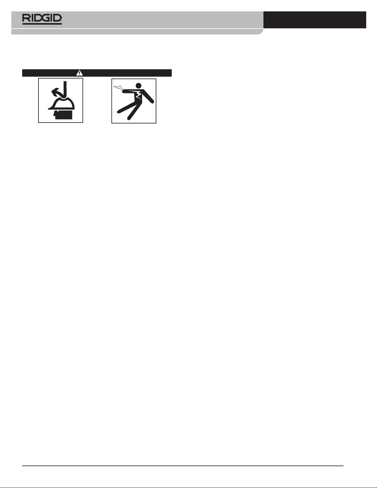
WARNING
Set up the Hole Cutting Tool and work area ac-
cording to these procedures to reduce the risk of
injury from electrical shock, entanglement, crush-
ing and other causes and prevent tool damage.
Properly secure the Hole Cutting Tool to the pipe.
Improperly secured Hole Cutting Tools can slip and
fall and cause striking and crushing injuries.
Do not use for hot tapping. When cutting into an
existing system, the pipe must be drained and de-
pressurized prior to cutting.This reduces the risk of
electrical shock and other serious injuries.
When working overhead, all personnel should wear
hard hats and be clear of the area below. This re-
duces the risk of serious injury should equipment
or other objects fall.
1. Check work area for:
•Adequate lighting.
•Flammable liquids, vapors or dust that may ig-
nite. If present, do not work in area until sources
have been identified and corrected.The hole cut-
ter is not explosion proof and can cause sparks.
•Clear,level,stable, dry locationfor allofthe equip-
ment and operator.
•Properly grounded electrical outlet of the correct
voltage. A three prong or GFCI outlet may not be
properly grounded. If in doubt, have outlet in-
spected by a licensed electrician.
• Clearpathtoelectricaloutletthatdoesnotcontain
any potential sources of damage for the power cord.
2. Inspect the work to be done. Determine the pipe
type and size, and clearance around the pipe. De-
termine the size and location of the hole to be cut.
Clearly mark the cut location. If installing a fitting,
follow the fitting manufacturer’s instructions. De-
termine the correct equipment for the job. See the
Description and Specification sections for tool infor-
mation.
Make sure that the pipe to be cut is well support-
ed and stable. The pipe must be able to handle
the weight of the Hole Cutting Tool and the forces
applied during cutting without moving.
If working on an existing system, make sure that
the system has been depressurized and drained.
The Hole Cutting Tools are not designed for hot
tapping purposes. Cutting into pressurized or
systems with fluids in them can cause spills, elec-
trical shock and other serious injury. Know the
contents of the pipe and any specific hazards as-
sociated with the contents.
3. Confirm that the equipment to be used has been
properly inspected.
4. Select an appropriate hole saw for the work to be
performed. Make sure that the hole saw is prop-
erly assembled per its instructions and is in good
working order. The use of a pilot drill is recom-
mended. The pilot drill should extend no more
than 3/8”/ 10 mm past the end of the hole saw, and
should be securely tightened.
5. With the Hole Cutting Tool on a stable surface, in-
stall the hole saw into the chuck. Always make sure
that the ON/OFF switch is in the OFF position and
the Hole Cutting Tool is unplugged before install-
ing or changing the hole saw or drill.
•Open the chuck wide enough for the shank of the
hole saw. If needed, the chuck key can be used
to open the chuck. Make sure that the shank and
the chuck jaws are clean.
•Fully insert the shank into the chuck. Make sure
that the hole saw is centered in the chuck and
firmly tighten the chuck by hand.
•Use the chuck key in all three chuck holes to se-
curely tighten the chuck onto the shank. Make
sure to remove the chuck key from the chuck be-
fore turning the tool ON.
MountingThe Hole CuttingTool On
The Pipe
Hole Cutting Tools weigh up to approximately
42 pounds / 19 kg. Use good lifting technique when
placing on the pipe, do not overreach, and keep
good balance and footing at all times. Depending
on the circumstances, two people may be neces-
sary to mount the Hole Cutting Tool onto the pipe.
Hole Cutting Tools can be used at any angle or orienta-
tion. If cutting a hole on the side or bottom of a pipe,
it may be easier to place the Hole Cutting Tool on the
top of the pipe to fasten the chain around the pipe and
then move the Hole Cutting Tool into final position.
HC-450
1. Make sure the chain is hanging freely and the swiv-
el handle is fully loosened.
2. Carefully lift the HC-450 Hole CuttingTool and place
with the V-shaped guides squarely on the pipe near
the location of the cut. Make sure the chain is not
between the pipe and tool base.