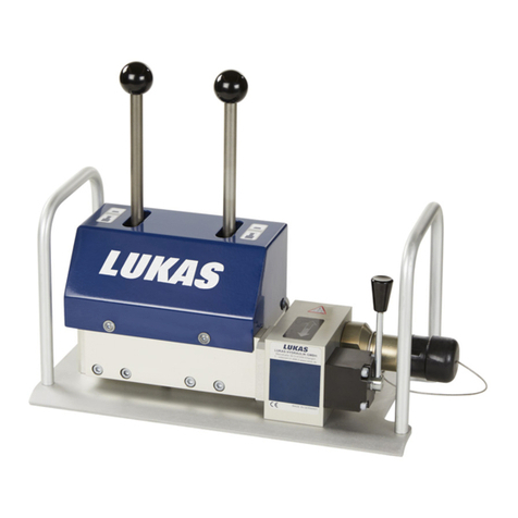
Lukas H1 User manual

Operating instructions for rescue equipment
84150012085 EN
H1 and H2 Lifting Sets (DIN 14800)
(Translation of the original operating instructions)
replaces 03.2008
Edition 03.2015
Lifting Set H1
Lifting Set H2

2

3
Content Page
1. Danger classifications 4
2. Product safety 5
3. Appropriate use 8
4. System description and overview 10
4.1 Design of the system and connection of the components 10
4.2 Commissioning and control 12
5. Lifting and lowering of loads 14
5.1 Lifting a load 14
5.2 Lowering a load 15
6. Accessories 16
6.1 Base plate 16
6.2 Extension 16
6.3 Wedge block (Expansion wedge) 16
6.4 Foot lifter 17
7. Maintenance and repair 18
7.1 General information 18
7.2 Function and load test 19
7.3 Signs 19
8. Troubleshooting 20
9. Technical data 23
9.1 Technical data of the hydraulic cylinder 23
9.2 Technical data of the Hand pump 24
9.3 Technical data of lifting set H1/H2 25
9.4 Dimensions of the transport crate 25
9.5 Operating and storage temperature ranges 25
10. Declaration of conformity 26
11. Instructions regarding disposal 27
12. Notes 27

4
Wear a helmet with a face guard
Wear protective gloves
Wear safety shoes
Proper recycling
Protect the environment
Read and follow the operating instructions
We differentiate between various different categories of safety instructions. The table shown
below provides an overview of the assignment of symbols (pictograms) and signal words to
the specific danger and the possible consequences.
1. Danger classifications
Pictogram Damage /
injury to Key word Definition Consequences
Persons
DANGER! Immediate danger Death or severe
injury
WARNING!
Potentially
dangerous
situation
Potential death or
serious injury
CAUTION! Less dangerous
situation
Minor or slight
injury
Property
ATTENTION!
Risk of damage
to property/
environment
Damage to the
equipment,
damage to the
environment,
damage to
surroundings
- NOTE
Handling tips and
other important/
useful information
and advice
No injury/damage
to persons/
environment/
device

5
2. Product safety
LUKAS products are developed and manufactured to ensure the best performance and
quality when used as intended.
The safety of the operator is the most important consideration in product design. Furthermore,
the operating instructions are intended to help in using LUKAS products safely.
The generally applicable legal and other binding regulations pertaining to the prevention of
accidents and protection of the environment apply and are to be complied with in addition to
the operating instructions.
The equipment must only be operated by persons with appropriate training in the safety
aspects of such equipment – otherwise, there is a danger of injury.
We would like to point out to all users that they should read carefully the operating instructions
and the instructions contained therein before they use the equipment, and that they should
be carefully followed.
We also recommend that you have a qualified trainer show you how to use the product.
WARNING / CAUTION!
The operating instructions for accessories must also be taken into account!
Even if you have already received instruction on how to use the equipment, you should still
read through the following safety instructions again.
WARNING / CAUTION!
Please ensure that the accessories you use are appropriate for the maximum
operating pressure and the performance of the rescue device!
Please ensure that no body
parts or clothing get stuck
between the visibly moving
parts.
Working under suspended
loads is not permitted where
such loads are being lifted
solely by means of hydraulic
or electro-hydraulic devices.
If this work is unavoidable,
suitable mechanical supports
are also required.
Wear protective clothing, safety
helmet with visor, safety shoes
and protective gloves.
Check the equipment for
visible flaws or damage before
and after use.

6
Immediately report any
changes that occur (including
changes in operating
behaviour) to the appropriate
persons/departments! If
necessary, the equipment is to
be shut down immediately and
secured!
All bolted connections must
be checked for leaks and
externally visible damage,
which must be repaired
immediately! Escaping
hydraulic fluid can cause
injuries and fires.
In the event of malfunctions,
immediately deactivate the
equipment and secure it.
Repair the fault immediately.
Do not carry out any changes
(additions or conversions)
to the equipment without
obtaining the approval of
LUKAS beforehand.
Observe all safety and danger
information on the device and
in the operating instructions.
All safety and danger
information on the device must
always be complete and in a
legible condition.
Any mode of operation which
compromises the safety and/
or stability of the device is
forbidden!
Repairs to the equipment may
only be carried out by a trained
service technician with specific
knowledge of the device.
Safety devices must never be
disabled!
Only genuine LUKAS
accessories and spare parts
are to be used for repairs.
Make sure before switching
on/starting up the device and
during its operation that this
will put no one in danger.
Observe all intervals for
recurring tests and/or
inspections that are prescribed
or stated in the operating
instructions.
When working close to live
components and cables,
suitable measures must be
taken to avoid current transfers
or high-voltage transfers to the
equipment.
Please note that materials can
fall off during lifting or lowering
or be slung away if a load is
suddenly released. Also take
suitable precautions of your
own.
Please ensure that you do not
become entangled in cables
and trip when working with or
transporting the device.
Please ensure that dust
protection caps are provided
for the couplings.

7
The equipment is filled with
hydraulic fluid. This hydraulic
fluid can be detrimental to
health if it is swallowed or
its vapour is inhaled. Direct
contact with the skin must
be avoided for the same
reason. Also, when handling
hydraulic fluid, note that it can
negatively affect biological
systems.
When working with or storing
the equipment, ensure that
the function and the safety
of the equipment are not
impaired by the effects of
severe external temperatures
or that the equipment is
damaged in any way. Please
note that the equipment can
also heat up over a long
period of use.
Make sure there is adequate
lighting while working.
Before transporting the
equipment, always ensure that
the accessories are positioned
in such a way that they cannot
cause an accident.
Always keep these operating
instructions easily accessible
at the place of operation.
Ensure the proper disposal of
all removed parts, left-over oil
and hydraulic fluid as well as
packaging materials!
Protect all of the lifting set
components against humidity
and moisture
The hand pump is not suitable
for underwater applications.
The build-up of static charge
and therefore possible
sparking must be avoided
when handling the device.
Always wear protective gloves
to prevent injury when touching
torn or sharp-edged parts.
The generally applicable, legal and other binding national and international regulations
pertaining to the prevention of accidents and protection of the environment apply and are to
be implemented in addition to the operating instructions.

8
3. Appropriate use
The LUKAS lifting sets are specially designed for the lifting or stabilising of heavy or movable
loads requiring lifting in order to free persons, vehicles or other objects from operations in
dangerous or catastrophic situations.
The lifting cylinders can also be used in all types of dangerous situations for the shifting or
lifting of objects to rescue buried or trapped persons or to recover any type of heavy object
(vehicles, devices, etc.).
Buildings in danger of collapsing or heavy vehicles in danger of crashing can be temporarily
secured and stabilised.
Thanks to the cylinder's low design, the lifting sets can be particularly well used for initial
lifting at low clearance heights between the object and the floor. The cylinder extensions can
additionally be used to increase the initial height of the stroke.
The cylinder unit of the lifting set is suitable for underwater applications. The hand pump
requires an air exchange through the tank cover of the hydraulic fluid container.
Additional safety instructions:
• Never use hydraulic cylinders without a base plate (stability). Use hard wood
spacers if possible to provide additional stability of the load.
• Never use more than one extension per cylinder (risk of buckling with multiple
arrangements).
• Always load the hydraulic cylinder in the centre (in the direction of the cylinder axis)!
Exception: Use of the foot lifter according to instructions.
• Work with a support bar when using the foot lifter (see Accessories section).
Screw the foot lifter on in reverse for loads with low internal strength and use it
without the support bar. Use suitable underlays or support bars to provide additional
support if necessary.
• Always lay the hoses to be free of twists and kinks!
• Pay extremely close attention to the moving load during the lifting and lowering
processes!
• Always provide additional mechanical support to raised loads!
• No bystanders are allowed in the hazard zone!
WARNING / CAUTION / ATTENTION!
The system is exclusively intended for the purpose stated in the operating instructions
(see section "Appropriate Use"). Any other use is not considered appropriate.
The manufacturer/supplier is not liable for any damage resulting from inappropriate use.
The user bears sole responsibility for such use.
Appropriate use includes observance of the operating instructions and compliance with the
inspection and maintenance conditions.
Never work in a fatigued or intoxicated state!

9
WARNING / CAUTION / ATTENTION!
The following may not be pressurised or squeezed:
- electric cables
- prestressed and hardened parts such as springs, spring steels,
steering columns and rollers
- tubes or containers under gas or liquid pressure
- explosive bodies such as airbag cartridges
The internally set operating pressure may only be directly changed after
consultation with LUKAS. A change in settings may result in damage to property
and/or injuries.
The H1and H2 lifting sets are not explosion protected!
When using the equipment in explosive areas you must rule out any chance of
the equipment causing an explosion.
The responsibility for explosion prevention or for prohibiting work with a lifting set
rests with the operator of the device or with the person responsible at the place
of use.
When working in explosive areas, all applicable legal, national
and international regulations, standards and safety rules for
avoiding explosions must be observed without restriction!
The lifting set should not come into contact with acids or alkalis. If this is
unavoidable, clean the equipment immediately afterwards with a suitable cleaning
agent.
You can obtain other accessories and replacement parts for the lifting sets from your
authorised LUKAS dealer!
WARNING / CAUTION!
Always ensure that the surroundings of the object to be lifted remain stable and
are secured against accidental shifting by sustainable supports or substructures.

10
4. System description and overview
4.1 Design of the system and connection of the components
2
1
A LUKAS lifting set generally includes a hydraulic hand pump which serves as a drive for
one or two single-acting hydraulic cylinders. Operating the hand pump presses hydraulic
fluid into the cylinder or cylinders, causing the cylinder piston to extend and lift an attached
load. The reset spring in the cylinder causes the cylinder to retract in the idle stroke or it is
retracted under loading by the force exerted by the attached load.
The components are joined together by connection hoses and couplings.
The accessories make it possible to optimally use the cylinders in any position desired at
the site.
The cylinders are controlled by the pump movement on the hand pump. The drain valve
must be closed to build up pressure. The hand wheels (distributor stop valves) must be open
when two cylinders are operated with 2-way distributors. A hydraulic load holding function
is provided when the isolating valves (distributors) are closed. You should also secure the
system mechanically when the cylinders are continuously loaded (under load).
4
5
4a
4b
33a3b
5a
Connection of two (2)
cylinders using the distributor
valve
Connection of one (1)
cylinder directly to the pump
1
1
5
5

11
Pos. Item no.
Components
H1 (Item No. 81-82-10)
H2 (Item No. 81-82-20)
H1
quantity
H2
quantity Group
1841500121 Cylinder LKZ 15/150 PN 700 with
male quick-disconnect coupling 22
Cylinder
841500122 Cylinder LKZ 15/50 PN 700 with
male quick-disconnect coupling 20
2
179112000 LH2/0 hand pump, 0.9-70 MPa,
with female quick-disconnect
coupling
21
Pump
38407126020 Hose assembly DN 6PN700-
2000RT 21Hose
3a HR149539213 Coupling nipple STNI 06 2 1
3b HR149539212 Coupling sleeve STMU61-M 2 1
4841489903 2-way distributor valve N2W 1 1 Distributor
4a HR149539210 Nipple STNI 06 1 1
4b 8407172 Connector M18x1.5 / R1/4 1 1
5KT149536275 Hose assembly DN6 PN 700/5000
RT 22
5a HR149539212 Coupling sleeve STMU61-M 2 2
841280606 Base plate for LKZ 15 2 2 Accessories
841280502 Foot lifter 100 - 150 kN 2 2
8403182 Extension 200 mm 2 2
8403178 Wedge attachment SL 9 2 2
HR148418965 Transport crate 2 1
8411720001 1 Litre hydraulic oil HM 10 ISO
6743-4 11
84150012085 Operating instructions for lifting set
H1 / H2 21
83145000085 Operating instructions for cylinder 2 1
179101085 Operating instructions for hand
pump 21
116500085 Operating instructions for hose
assemblies

12
Remove the components from the transport crate (H2 has two crates), set them up in
accordance with the operating situation and connect the components according to the diagram
as shown under the heading "Design of the system and connection of the components".
Please also follow the relevant operating instructions for the hydraulic cylinders, the hand
pump and the hose assemblies included in the scope of supply for the commissioning of
all components. All of the components are pre-filled with hydraulic fluid and vented before
shipment. The components are thus immediately operational and can be connected together.
Cylinder
The standard cylinders in the rescue set are equipped with male quick-disconnect cou-
plings. This has the advantage that the "quick stop" installed in the coupling system pro-
vides a highly effective safeguard. The quick-disconnect couplings have the additional ad-
vantage of preventing the oil (hydraulic fluid) from leaking when the unit is not connected.
If no attachment pieces are used, then a suitable padding must be laid between the piston
and the load to protect the piston flange.
In applications using the foot lift, the cylinders are equipped with an external thread
which is protected by a thread protection ring. This should remain on the cylinder as a
safeguard during all work not requiring the thread.
The cylinders can be used in any position desired. Care must always be taken here to
ensure that the force is applied vertically to the load and in the centre of the piston to
prevent damage to the top of the piston and to prevent it from tilting.
Connection of the cylinder
Remove the dust protection cap and any possible dirt particles before connecting the female
coupling to its male counterpart.
The male coupling can be inserted when the sleeve on the female coupling has been pulled
back. It locks in place when the sleeve is released (verify accurate locking).
Venting the cylinder- pump system, only when the piston moves jerkily
Jerky movements by the unloaded cylinder during extension and retraction is an indication
that air is located in the system.
The system is vented by activating the pump to extend the cylinder piston without loading.
The cylinder is then positioned downwards by the piston. They cylinder must not be located
at the same height as the pump, but must be lower. This allows the air to escape which is
forced into the pump's oil tank by the retracting piston. The tank closure cap on the pump
must remain loosened here to allow excess air escape to the outside.
Pressure release and the return flow of oil for retracting the hydraulic cylinders
Open the drain valve on the hand pump by turning it slowly to the left. The corresponding
hand wheel on the distributor valve must be open at the same time to allow oil from the
cylinder to flow back.
4.2 Commissioning and control

13
The female quick-disconnect coupling with quick-stop (Type StMu) between the cyl-
inder and the hydraulic hose is equipped with a "rapid halt function" which will block
the oil reflow from the cylinder if, for example, a hose breaks, and thus prevent the
load from being dropped. The cylinder then locks and can no longer be retracted.
First apply a few pump strokes (compression load) to extend the cylinder a few mil-
limetres. This unlocks the safety device. You can now initiate the lowering process
by slowly opening the drain valve on the pump.
NOTE:
Decoupling the pump and cylinder
The pump's drain valve must be opened to prevent any pressure from remaining in the
system and to ensure that the piston is fully retracted before the cylinder is disconnected
from the pump. The dust protection caps must be reattached or screwed back on after
decoupling to prevent soiling of the coupling halves. When commissioning the system,
please also follow the separate operating instructions for the hand pump, the cylinders and
the hose assemblies.
Distributor valve
Controlling the oil flow during cylinder extension:
When both hand wheels are open, each cylinder receives a part of the pump's oil flow pro-
portional to its load. The piston rod of the right-hand cylinder extends when the left-hand
wheel is closed. The piston rod of the left-hand cylinder extends when the right-hand wheel
is closed.
Controlling the oil flow during cylinder retraction:
The oil flows freely back to the pump when both hand wheels are opened and a communi-
cating pressure compensation occurs between the hydraulic cylinders. Each cylinder can
be drained separately. The corresponding hand wheel on the pump must be opened for
this.
NOTE:
Always follow the separately delivered operating instructions for the cylinders,
hand pumps and hose assemblies.

14
5.1 Lifting a load
Create the connection between pump and unloaded cylinder.
Proceed as follows:
- Lay the connecting hoses in a way that they are free of twists and kinks!
- Remove the protective caps from the male and female couplings, while ensuring extreme
cleanliness of both coupling components!
- Pull back the coupling sleeve on the female coupling, insert the male counterpart, allow the
sleeve to catch and lock.
- Check whether the coupling is locked precisely.
- Slightly open the tank closure (cap) on the hand pump so that air can circulate.
Three different operating conditions can occur during lifting:
1. The piston travels a part of its stroke with no loading (idle stroke) and then hits the load.
The pump operates here in the low pressure range during the idle stroke.
The pressure increases when the piston hits the load and the pump switches automatically
from its low to high pressure level. The load begins to rise.
The same applies when the load is so small that the change-over pressure is not reached.
2. The piston is loaded from the very beginning, i.e. it extends under load. The pump
then switches immediately to high pressure after a few pump strokes and the load is lifted.
Cylinder 1
Distributor stop valves
Cylinder 2
Drain valve
Base plate
Load
Stroke
Hand
pump
2-Way distributor valves
Application diagram
5. Lifting and lowering of loads
Tank closure (must be opened
during pump operation)
Hose 5 m
Hose 5 m
Hose 2 m

15
5.2 Lowering a load
The drain plug on the pump body must be slowly opened (turned to the left) to retract the
cylinder piston. The tank closure on the hand pump must first be opened so that excess air
can escape. The draining process is interrupted when the drain plug is closed (turned to
the right). Fine adjustment with the drain plug can be used to retract the cylinder piston with
millimetre precision.
Decoupling the pump and cylinder
The system must be completely depressurised and the piston completely retracted before
you disconnect the pump from the cylinder.
The protective caps for the male and female quick-disconnect couplings must be
reattached after decoupling to prevent soiling of the coupling components.
The tank closure cap on the pump's oil tank must be closed if it is not being used for a
prolonged period of time. This prevents leakage of hydraulic fluid during transport.
WARNING / CAUTION / ATTENTION!
Pay extremely close attention to the lifting process and load reaction to prevent
the load from slipping off!
The same applies for the lowering process, during which both of the distributor
stop valves are initially closed and the drain valve opened.
3. The load is above the maximum compression force of the cylinder, i.e. the cylinder does
not extend. When the maximum pressure of 700 bar is exceeded, the pressure limiting
valve routes the hydraulic fluid (hydraulic oil) back into the container. The escape of the
hydraulic fluid from the pressure limiting valve can be noticed by a pronounced hissing
noise in the hydraulic fluid container.
Initially ensure that both poisons are completely retracted when lifting one load with two
cylinders at the same time. Both distributor stop valves are opened, the drain valve on the
pump is closed. The cylinder with the smaller load always leads when the load is unevenly
distributed. This can be corrected by locking the corresponding side of the distributor.
Uniform lifting of the load can be achieved by alternating between sensitive closing and
opening of the distributor stop valves.
NOTE:
Always follow the separately delivered operating instructions for the cylinders,
hand pumps and hose assemblies.

16
Base plates enlarge the surface area of the cylinders and increase
their stability. The cylinder is placed in the base plate and attached
and secured by the wing bolt.
Fixing
bolt
6.1 Base plate
6.2 Extension
6.3 Wedge block (Expansion wedge)
The extension makes it possible to increase the stroke or bridge a
distance which the piston cannot reach for placement on the load.
The extension is attached to the piston.
Neither the front surface of the cylinder's piston nor the extension
should ever be placed directly on the load but always together with a
suitable padding. This prevents entrenchment in the load or damage
to the front surface. One extension (200 mm long) per cylinder is
included in the scope of supply.
WARNING / CAUTION!
Extensions may only be used with central power transmission! The usage of
more than one extension is prohibited. A multiple configuration poses a risk of
buckling.
The wedge blocks or expansion wedges enable the cylinder to be
attached to the edges of a load or attached in a slanted position.
This also enables specially shaped loads to be better lifted.
The wedge block is attached to the piston.
6. Accessories
NOTE:
- Always insert the cylinder together with the base plate
- Use additional suitable padding whenever possible

17
Inner thread
6.4 Foot lifter
1. The foot lifter can be screwed onto the cylinder to facilitate better
load lifting from the side.
Screw the foot lifter on in such a way that the step points upwards.
Place the load to be lifted on the step and position the support bar.
2. Sunken loads can be better lifted if the foot lifter is screwed in
with the full surface facing upwards and the cylinder reversed (see
application diagram).
For this purpose, screw the foot pedal on in a way that its smooth
side points to the piston rod (See illustration below). Set up the
cylinder with the piston side facing downwards and place a suitable
padding between the piston front and the floor.
NOTE:
- Always screw in the threads up to the stop
- Always use the foot lifter together with a suitable support bar (not in the
accessories)
- Apply additional mechanical support to raised loads
Application diagram: Foot lifter
Foot lifter
Load
Support bar
Load
Foot lifter
Additional instructions for
using the accessories:
• Never use hydraulic cylinders without
a base plate (stability). Use spacers
(padding) if possible to provide additional
stability of the load.
• Never use more than one extension per
cylinder (risk of buckling with multiple
arrangements).
• Always load the hydraulic cylinder in the
centre (in the direction of the cylinder
axis)! Exception: Use of the foot lifter
according to instructions.
• Work with a support bar when using
the foot lifter. Screw the foot lifter on in
reverse for loads with low internal strength
and use it without the support bar.
Padding
Padding
Step

18
ATTENTION!
When cleaning units and equipment, note that no cleaning agent may be used
that has a pH value outside the range 5 - 8!
7. Maintenance and repair
Service work may only be performed by the device manufacturer or by personnel trained by
the device manufacturer and authorised LUKAS dealers.
Only LUKAS spare parts may be used to replace all components (see spare parts list), as
special tools and compliance with assembly instructions, safety aspects and inspections are
required (see also chapter "Maintenance and Servicing").
During assembly work, pay particular attention to the cleanliness of all components
since dirt can damage the lifting sets and components and cause functional
disturbances!
WARNING / CAUTION / ATTENTION!
Protective clothes must be worn when repairs are being carried out, as the
devices may also be pressurised when not in operation.
ATTENTION!
Because LUKAS devices are designed for the highest performance, only
components may be replaced that are listed in the spare parts lists of the
corresponding device.
Other components in the device may only be replaced if:
- You have participated in an appropriate LUKAS service training course.
- You have the express permission of LUKAS Customer Service (valid LUKAS
certificate required!)
The cylinders and all of the individual components require only minimum care and
maintenance. Care should be taken however to ensure that the piston rods of the cylinder
and the quick-connect coupling halves and valve coupling halves remain free of dirt. Be
aware of leakage during every usage.
Even the hand pumps require only minimum care and maintenance. Always make sure that
no dirt gets into the oil tank or the pump itself because functional disturbances can otherwise
occur.
The oil (hydraulic fluid) should be replaced at least once a year. The oil should be change
every six months in cases of frequent operation or operation in particularly dusty surroundings.
When performing maintenance and repair, please also follow the separate operating
instructions for the hand pump, the cylinders and the hose assemblies.
7.1 General information

19
All damaged and/or illegible labels (safety notices, type plate, etc.) must be replaced.
Procedure:
1. Remove damaged and/or illegible decals.
2. Clean surfaces with industrial alcohol.
3. Affix new decals.
Take care to affix the labels in the correct positions. If this is no longer known, you should ask
your authorised LUKAS dealer or contact LUKAS directly.
NOTE:
Always follow the separately delivered operating instructions for the cylinders,
hand pumps and hose assemblies with respect to maintenance and repair.
7.2 Function and load test
7.3 Signs
A visual inspection must be carried out after every use, but at least once a year.
Every 3 years or when there might be doubts regarding the safety or reliability of the unit, an
additional function check is to be carried out (in this connection, comply with the applicable
national and international regulations with regard to the maintenance intervals of rescue
equipment). Operating time per day In the Federal Republic of Germany, regular safety
inspections according to the regulations of the Gesetzlichen Unfallversicherung (GUV;
connoted ‘Legal accident insurance’) are mandatory.
A function and load test must also be performed whenever there is any doubt regarding the
safety or reliability of a device,
(In case of doubt, contact your authorised LUKAS dealer, LUKAS service centre or LUKAS
directly!)

20
8. Troubleshooting
Fault Cause Solution
Connected device does not
move, moves only slowly
or moves intermittently.
Insufficient fluid in the
hydraulic reservoir.
Top up hydraulic fluid to the
maximum fill level
Discharge valve open Close discharge valve
Hose assembly not
connected properly or
damaged
Check hose connection and
reconnect if necessary
Air in hydraulic system Bleed the system as
described in the “Bleeding
the hand pump” section
of the separate operating
instructions
Valve block defective Replace the valve block
Have repaired by authorised
dealer or directly by LUKAS
Defect on the device Heed the specifications
of the separate operating
instructions of the device.
Connected device moves,
but does not hold pressure
or does not render the
specified performance.
Hose assembly not
connected properly or
damaged
Check hose connection and
reconnect if necessary
Leaking seal Locate the leak and have
the hand pump serviced by
an authorised dealer, by
personnel specially trained
by LUKAS or by LUKAS
directly.
Internal leakage of the
pump
Have the hand pump
serviced by an authorised
dealer, by personnel
specially trained by LUKAS
or by LUKAS directly.
This manual suits for next models
1
Table of contents
Other Lukas Lifting System manuals
Popular Lifting System manuals by other brands

Stage right
Stage right AlphaRoll Series Product information packet

SmartMetals
SmartMetals Predia Wall lift product manual

Bend-Pak
Bend-Pak XPR-10XLS-LP-181 Service manual

PRO LIFTS
PRO LIFTS VMB TL-A400/8 Operating instructions & user manual

Stage right
Stage right 360168 Product information packet

Bend-Pak
Bend-Pak HD-14T Service manual