CLASSIC LIFT CL6500-4P Manual
Original
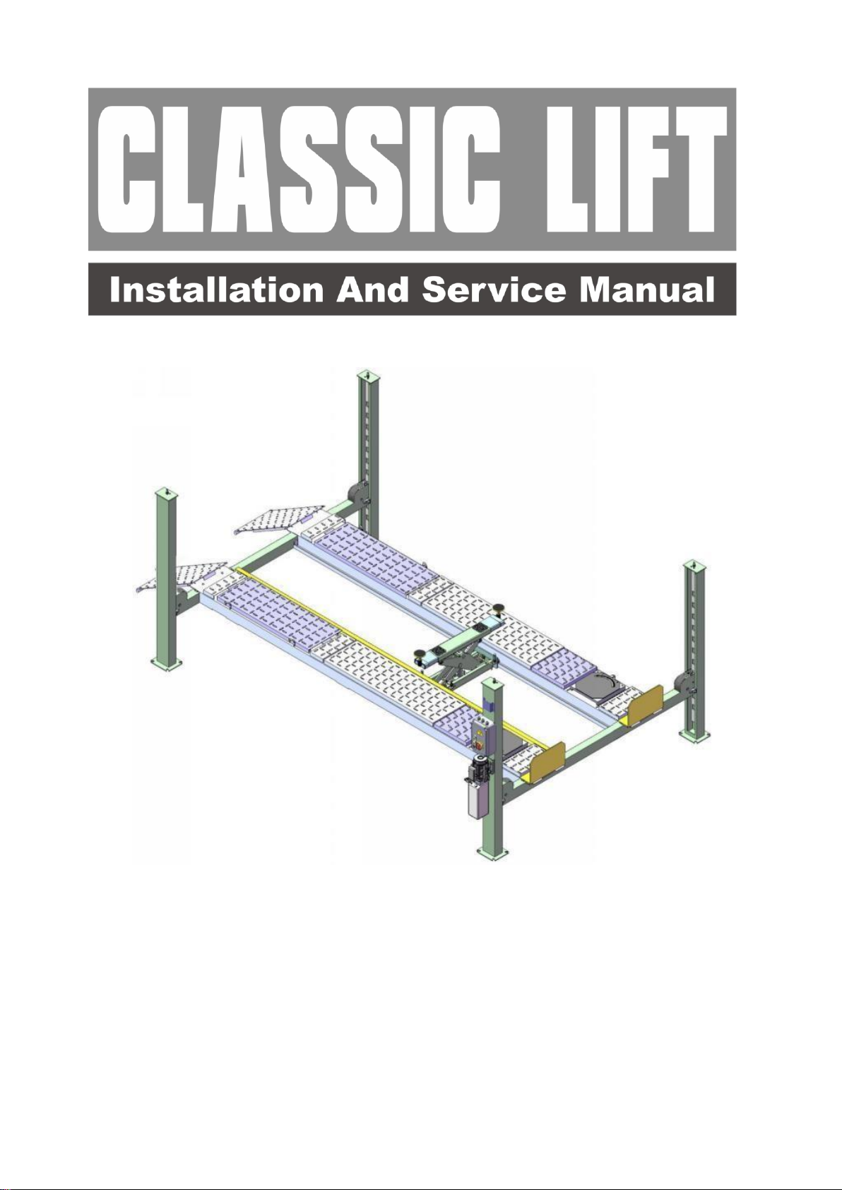
4-post Lift
Model Classic CL6500-4PAE

CONTENTS
Product Features and Specifications ..................................................... 1
Installation Requirement ……………………………………………………………………… …….. 3
Steps of Installation …...................................... ................................. 5
Explosive view……………....................................................................... 36
Test run……….....................................................................................49
Operation instruction .........................................................................51
Maintenance ………………………………………………………………………………………………….52
Trouble Shooting …………………...............................................................53
Scarping of Equipment…..................................................................53
1
I. PRODUCT FEATURES AND SPECIFICATIONS
FEATURES
· Electric-air control operation system.
· Mechanical self-lock and air-drive safety release.
· Electrical hydraulic power system, cable-drive.
· Non-skid diamond platforms.
· Multiple turnplate pockets fit with different wheel base.(Only for alignment model.)
· Adjustable platform and adjustable safety lock ladders.
· Optional Jack: with Pneumatic hydraulic pump
. Optional Turnplate (Only for alignment model.)
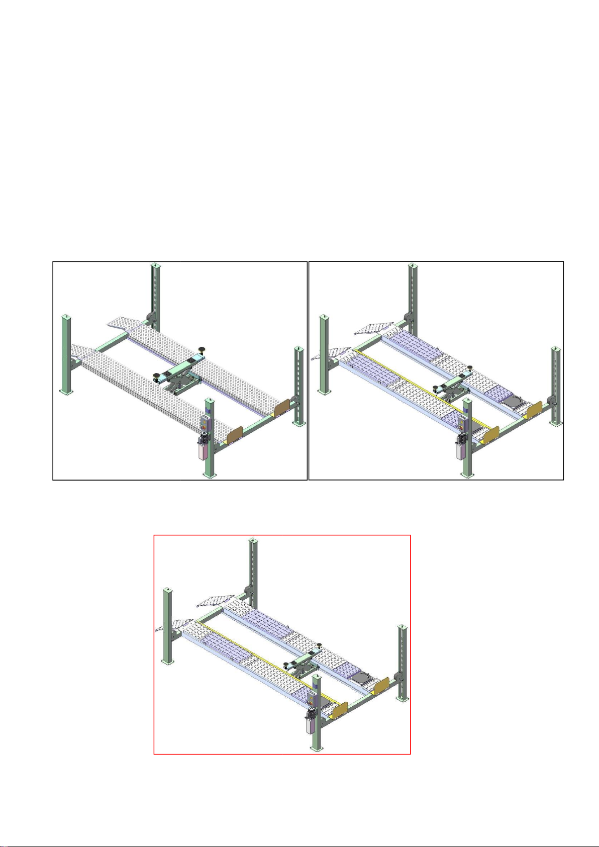
CL6500-4P
Fig.1
CL6500-4PA
Fig.
2
CL6500-4PAE
Fig.
3

2
SPECIFICATIONS
Model
Lifting
Capacit
y
Lifting
Height
Lifting
Time
Overall
Length
(Inc.
Ramps)
Overall
Width
Width
Between
Columns
Motor
CL6500-4P
6500KG
1865mm
65S
6541mm
3324mm
2946mm
4.0HP
CL6500-4PA
6500KG
1915mm
65S
6528mm
3324mm
2946mm
4.0HP
CL6500-4PAE
6500KG
1915mm
65S
7252mm
3324mm
2946mm
4.0HP

3
II. INSTALLATION REQUIREMEN
A. TOOLS REQUIRED

4
# #
Rotary
Hammer
Drill
(
Φ
19)
Carpenter
’
s
Chalk
Hammer
Screw
Sets
Level
Bar
Tape
Measure
(7.5m)
English
Spanner
(12")
Pliers
Wrench
Set
Lock
Wrench
(10
,
12
,
13
,
14
#
,
17
#
,
19
#
,
24
#
,
30
#
)
Ratchet
Spanner
With
Socket
(28
#
)
Socket
Head
Wrench
(3
#
,
5
#
,
6
#
)

5
#
Fig. 4

- 6 -
B. Equipment storage and installation requirements.
The equipment should be stored or installed in a shady, normal temperature,
ventilated and dry place.
C. SPECIFICATIONS OF CONCRETE (See Fig. 5)
Specifications of concrete must be adhered to the specification as following.
Failure to do so may result in lift and/or vehicle falling.
1. Concrete must be thickness 100mm minimum and without reinforcing steel bars
,and must be dried totally before the installation.
2. Concrete must be in good condition and must be of test strength 3,000psi
(210kg/cm²) minimum.
3. Floors must be level and no cracks.
Fig. 5
D. AIR SUPPLY
Air pressure requirement: 0.5Mpa~0.8Mpa, Air line size ¢8×¢6 and ¢6×¢4.
E. POWER SUPPLY
The electrical source must be 3KW minimum. The source cable size must be 2.5mm²
and in good condition of contacting with floor.
III. STEPS OF INSTALLATION
A. Location of installation
Check and insure the installation location (concrete, layout, space size etc.) is
suitable for lift installation.
- 7 -
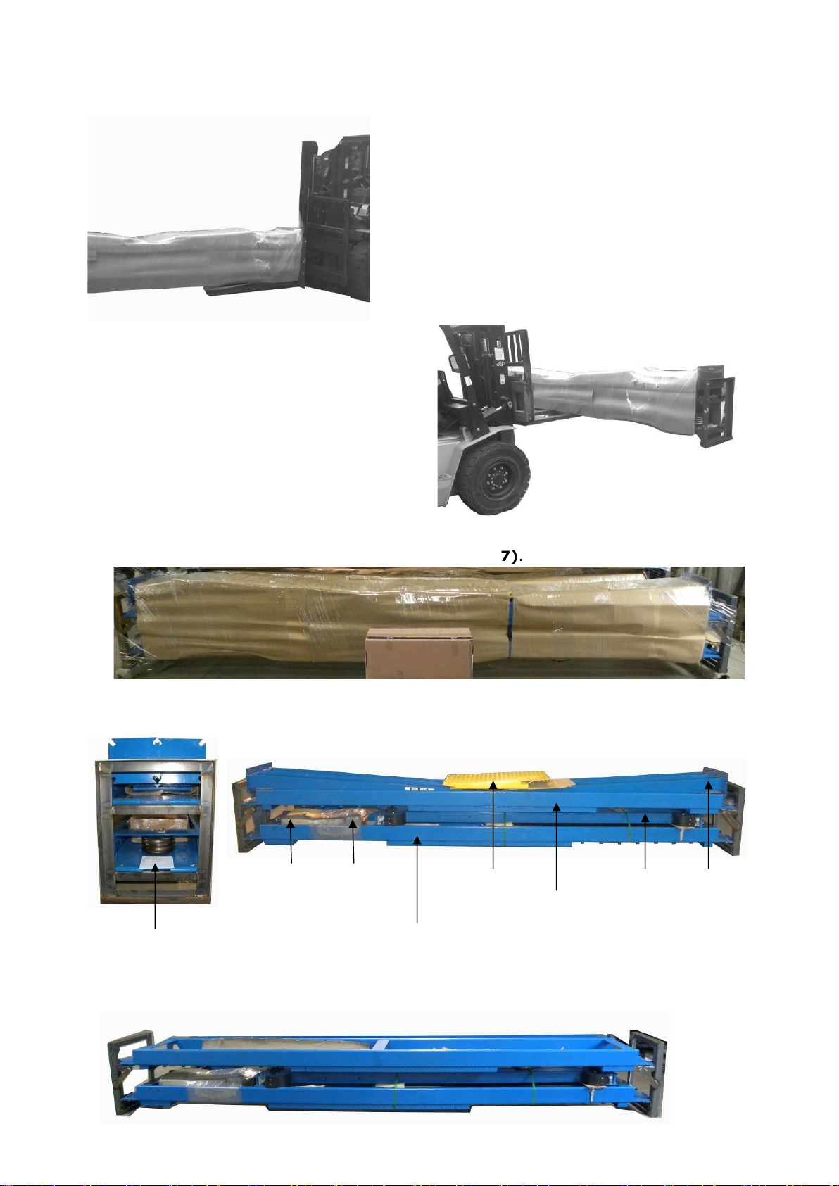
B. Check the parts before assembly
1. Transmit by forklift.(See Fig. 6).
Fig. 6
2. Packaged lift and hydraulic power unit (See Fig. 7).
Fig. 7
3. Open the outer packing carefully (See Fig. 8).
Fig. 8
3. Take off the drive-thru ramps and columns (See Fig. 9).
×
√
Shipment
Parts
List
Control
box
Power
-
side
Platform
Drive-
in
Ramp
Offside
Platform
Cross
Beam
Column
Parts
box

the
- 8 -
Fig.9
4. Loose screws of the upper package stand, take off the offside platform, take out the
parts inside the power-side platform, than remove the package stand.
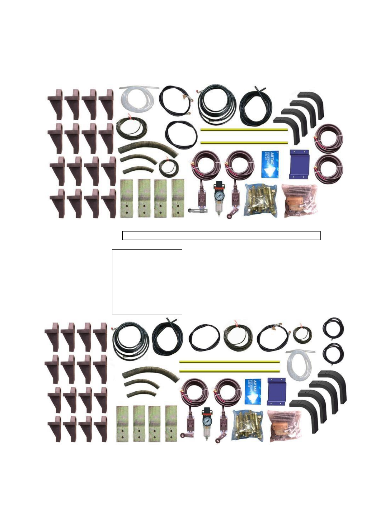
5. Move aside the parts and check the parts according to the shipment parts list
(See Fig. 10,11).
5.1. Model CL6500-4P
Fig. 10
5.2. Model CL6500-4PA, CL6500-4PAE

- 9 -
Fig. 11
the
- 10 -
6. Open carton of parts and check the parts according to the parts box list (See
Fig. 12, 13).
6.1. Model 414, 414E,418
Only for 414, 414E
Fig. 12
6.2. Model CL6500- 4PA, CL6500-4PAE
CL6500-4PAE
Fig. 13
7. Check parts of the parts bag according to the parts bag list. (See Fig. 14)
Only for CL6500-4PA,

- 11 -
7.2. Model CL6500-4PA, CL6500-4PAE
Fig. 15
C. Use a carpenter’s chalk line to establish installation layout as following Table.
7.1.
Model
CL6500-4P,
CL6500-4PE
Fig.
14

the
- 12 -
Make sure the size is right and base is flat (See Fig. 16.)
Note: Reserve space front and behind the installation site.
Fig. 16
Model
A
B
C
CL6500-4P, CL6500-
4PA
5500mm
3324mm
6426mm
CL6500-4PAE
6224mm
3324mm
7056mm
Use
a
carpenter
’
s
chalk
line
to
establish
installation
layout
Car
in
Direction

- 13 -
E. Fix the anchor bolts
1. Prepare the anchor bolts (See Fig. 18).
Lock washer
Washer Nut
Fig. 18
2. Using the prescribed rotary hammer drill, and drill all the anchor holes and install
the anchor bolts. Do not tighten the anchor bolts (See Fig. 19). Note: Minimum
embedment of Anchors is 90mm
D.
Install
c
ross
b
eams
(
See
Fig.
17)
.
Fig.
17
Hole
towards
inside
1
2
3
3
Dril
l
ing
Clearing
Bolting
Fig.
19

- 14 -
F. Install the safety ladders
1. Take off one nut from the pulley safety cover and safety ladders, and then adjust
the four lower nuts to the same position. Then install the safety ladders.(See Fig.
20).
2. Install safety ladders (See Fig. 21).
This height should
be the same for
four safety ladders
Safety ladder pass
through the hole of the
top plate, then tighten
the two nuts.
Fig. 21
G. Put the cross beams at the same height (See Fig. 22).
Fig.
20
Limit
Pin
Limit
Pin
Safety
Ladder
Safety
Ladder
is
inserted
between
Limit
Pins

- 15 -
should lock at same
ladders.
Fig.
22
L
ifting
both
cross
beams
to
the
same
height,
it
is
recommended
about
1
meter
height.
The
four
safety
locks
position
of
the
safety
2
cross
beams
should
at
the
same
height.
- 16 -
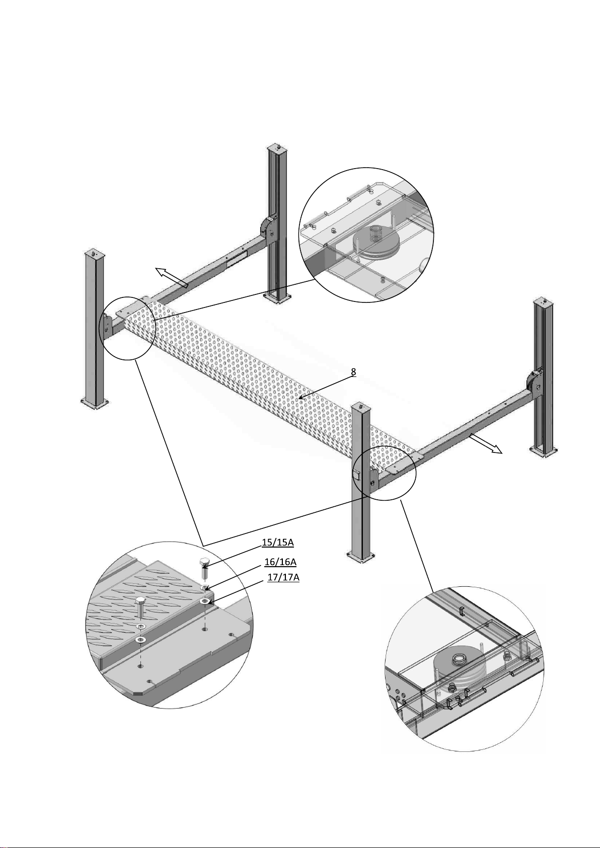
H. Install power side platform.
1. Put the power side platform upon the cross beams by fork lift or manual, offset the
cross beams to the outside till the pulleys of both platforms can set up into the cross
beams (See Fig.23). Install the power side platform and screw up the bolts(See
Fig.24).
Fig.
24
Offset
the
cross
beam
lean
outward
when
putting
the
power
side
platform
on
the
cross
beams
Tighten
the
power
side
platform
and
cross
beam
with
bolts
CL6500-4P
,CL6500-4PA
,
CL6500-4PAE
:
M16*40
Bolts
Pulley
installation
Fig.
23
Pulley
installation

- 17 -
2. Assembly offside platform and slider block, check the plumbness of columns with
level, adjusting with the shims if not, and then tighten the anchor bolts (See Fig.
25).
Note: The tightening torque for the anchor bolt is 150N.m
Fig. 25
J. Install cables (See Fig. 26).
1. Install the cable which has roll on the platform to the column as number.
Using
the
Ratchet
S
panner
W
ith
S
ocket
to
t
ighten
the
bolt
s
Install
the
slider
block

- 18 -
2. The cable pass through the cross beam to top plate of columns and be screwed with
No.
Cable
○
1
○
2
○
3
○
4
CL6500-4P,
CL6500-4PA
Length
(
inc.
connecting
fitting)
4135
mm
1
1138
mm
5
855
mm
9425
mm
CL6500-4PAE
Length
inc.
(
connecting
fitting)
4860
mm
12588
mm
6580
mm
10875
mm
Fig.
26
This manual suits for next models
2
Table of contents
Other CLASSIC LIFT Lifting System manuals


Popular Lifting System manuals by other brands

Logan
Logan 85-Ton Open Loop Power Swivel user manual

human care
human care SINGEL 5100 Herkules user manual

Rotary
Rotary 600 Series Operation & maintenance manual

Easy Lift Equipment
Easy Lift Equipment EAGLE-GRIP EL4 Series operating instructions

Pressalit
Pressalit R8515 Assembly instruction

Snorkel
Snorkel SR2770 Operator's manual


