LGMG AR16J User manual

Maintenance Manual
AR16J
Mobile Elevating Work Platform
△
!Warning
Before operation and maintenance, the
drivers and service personnel shall
always read and thoroughly understand
all information in this manual. Failure to
do so may result in, fatal accidents or
personal injury.
This manual must be kept with this
machine at all times..
LINGONG GROUP JINAN HEAVY MACHINERY CO., LTD.

Mobile Elevating Work Platform
Maintenance Manual
880*1230 mm 16 format 8 printed sheets
First edition and printed for the first time in December 2021
Lingong Group Jinan Heavy Machinery Co., Ltd.
Add: 12th Floor, Building 3, Lushangguoaocheng, 9777 Jingshi Road, Lixia District, Jinan,
China
Tel: 86-0531-67605017 Fax: 86-0531-67605017
Technical service: 86-0531-67605017 Web: www.LGMG.com.cn
Accessories sales: 86-0531-67605016

Maintenance Manual of Elevating Work Platform
II
Contents
Foreword....................................................................................................III
Safety Precautions....................................................................................IV
Chapter 1 Maintenance...............................................................................1
1.1 Compliance and Obedience.............................................................. 3
1.2Check for Batteries............................................................................ 3
1.3Maintenance of worm-Type Slewing Drive......................................... 4
1.4Check Hydraulic Oil Level.................................................................. 5
1.5 Check for the Oil Level in the Reducer.............................................. 5
1.6 Replacement of the Gear Oil of Reducer.......................................... 6
1.7 Check for Engine Oil Level ............................................................... 6
1.8 Replacement of Engine Oil and Filter ............................................... 7
1.9 Check for Fuel Leakage.................................................................... 8
1.10 Vent Fuel Pre-Filter......................................................................... 8
1.11 Replacement of the Fuel filter ....................................................... 10
1.12 Check for Engine Air Filter............................................................ 10
1.13 Cleaning or Replacement of Air Filter.............................................11
1.14 Check for Coolant Liquid Level..................................................... 12
1.15 Filling or Replacement of Engine Coolant..................................... 12
1.16 Check for Engine Belt................................................................... 13
1.17 Regular Maintenance.................................................................... 13
1.18 Engine fault table.......................................................................... 14
1.19 Engine fault codes........................................................................ 16
Chapter 2 Schematic Diagram ..................................................................23

Maintenance Manual of Elevating Work Platform
III
Foreword
Thank you for choosing to use this Mobile Elevating Work Platform from LGMG. This machine is
designed according to AS/NZS1418.10:2011+A1:2017.The information specified in this manual is
intended for the safe and proper operation of this machine for its’ intended purpose.
For maximum performance and utilization of this machine, thoroughly read and understand all the
information in this manual before starting, operating, or performing maintenance on this machine.
Due to continuous product improvements, LGMG reserves the right to make specification changes
without any prior notifications. For any updated information, contact LGMG.
Ensure all preventive maintenance to the machine is performed according to the interval specified in the
maintenance schedule.
Keep this manual with this machine for reference at all times. When the ownership of this machine is
transferred, this manual shall be transferred with this machine. This manual must be replaced
immediately if it is lost, damaged, or becomes illegible.
This manual is copyrighted material. The reproduction or copy of this manual is not allowed without the
written approval of LGMG.
The information, technical specifications and drawings in this manual are the latest available when this
manual is issued. Due to continuous improvement, LGMG reserves the right to change the technical
specifications and machine design without notice. If any specifications and information in the manual are
not consistent with your machine, contact the service department of LGMG
△
!WARNING
Only personnel who have been properly trained and qualified to operate or
maintain this machine can operate, repair and maintain this machine.
Improper operation, maintenance, and repair are dangerous and can cause
personal injury and death.
Before any operation or maintenance, the operator shall thoroughly read this
manual. Do not operate, perform any maintenance or make any repairs on this
machine before reading and understanding this manual.
The user shall load the platform strictly according to the load rating of the
platform. Do not overload the platform or make any modifications to the platform
without permission from LGMG.
The operation regulations and preventions in this manual are only applicable for
the specified use of this machine.

Maintenance Manual of Elevating Work Platform
IV
Safety Precautions
The operator of this machine shall understand and follow the existing safety regulations of state and
local governments. If these are unavailable, the safety instructions in this manual shall be followed.
To help prevent accidents, read and understand all warnings and precautions in this manual before
operation or performing maintenance.
The safety measures are specified in Chapter 1 Safety.
It is impossible to foresee every possible hazard and the safety instructions in this manual may not cover
all safety prevention measures. Always ensure the safety of all personnel and protect the machine
against any damage. If unable to confirm the safety of some operations, contact LGMG.
The operation & maintenance prevention measures listed in this manual are only applicable to the
specified uses of this machine. LGMG assumes no responsibility if this machine is used beyond the
range of this manual. The user and the operator shall be responsible for the safety of such operations.
Do not perform any operation forbidden in this manual in any situation.
The following signal words are applicable for identifying the level of safety information in this manual.
△
! Danger:
An imminent situation, that if not avoided, will result in severe injuries or death. This
is also applicable to situations that will cause serious machine damage, if not
avoided.
△
! Warning:
A potentially dangerous situation, that if not avoided, may result in severe injuries or
death. This is also applicable to situations that may cause serious machine damage,
if not avoided.
△
! Notice:
A situation, that if not avoided, may result in minor or intermediate injury. This is also
applicable to situations that may cause machine damage or shorten machine service
life..

Maintenance Manual of Elevating Work Platform
1
Chapter 1 Maintenance

Maintenance Manual of Elevating Work Platform
2

Maintenance Manual of Elevating Work Platform
3
1.1 Compliance and
Obedience
1) The operator is only allowed to perform
routine maintenance items as specified in
this manual.
2) Carry out periodic maintenance and check
by trained maintenance technicians as
required by the manufacturer.
Maintenance Symbols
The following symbols are used in this manual
to help convey relevant meanings in the
instructions. When one or more symbols are
shown at the first part of the maintenance
program, the meanings expressed are as
follows.
It indicates a tool required to carry out this
procedure.
It indicates a new part required to carry out this
procedure.
It indicates that the engine must be in a cooling
state before carrying out this procedure.
1.2Check for Batteries
A sound battery condition is critical to good
engine performance and safe operation.
Improper electrolyte levels or damaged cables
or wires may cause damage to engine
components and bring hazardous conditions.
△
!Danger: Explosion Danger!
Electric Shock Danger! Burn Danger!
Keep away from fire, remove all rings,
watches and other jewelry. If necessary,
wear goggles, protective gloves and
protective clothing. Avoid contacting
overflowed electrolyte, and neutralize
any overflowed electrolyte with sodium
bicarbonate solution.
It is crucial for machine performance and
security-related operations to keep the battery
in proper condition. Improper voltage or
damaged cables and wires may cause damage
to components and danger. Inspect the battery
every 8 hours or daily.
Ensure the battery hold down hardware is
secure.
Inspect the battery cables for corrosion.
Inspect for fluid leaks, and whether or not
the battery is dry and clean.
Inspect the color of the battery hydrometer
(if applicable):
Hydrometer
Color
Meaning and Handling
Method
White
Lack of battery fluid,
please shut down the
machine, and stop using
Black
Lack of electricity
Green
Measure the voltage of
each battery, and voltage
lower than 11V indicates
damage to battery; and
voltage between 12.4V
and 12.7V indicates that
the battery is in good

Maintenance Manual of Elevating Work Platform
4
state
Color and description of hydrometer color
If the battery hydrometer’s color is green,
and voltage is more than 12V, but cannot drive
the starter, further check the battery circuits by
personnel with machine maintenance training
and certified to perform such work.
△
!Caution: If charging the battery
with an external power supply, only
use a charger accepted by LGMG.
Periodic maintenance
1) Maintenance items every quarter, every
year and every two years must be
performed by personnel with machine
maintenance training and certified to
perform such work.
2) A machine not used for a time exceeding
three months must not be put into use
again until a quarterly inspection and
maintenance have been performed.
Battery hydrometer
1.3Maintenance of
worm-Type Slewing Drive
There are three positions to be lubricated on the
worm-type slewing drive assembly, i.e.,
lubrication of the roller path (Position I),
lubrication of the engaging position (Position II)
between the worm and the slewing bearing, and
lubrication of the tapered roller bearing (Position
III). The specific lubrication positions are shown
as below:
Figure 1-1
Figure 1-2
1.3.1Maintenance before Delivery
△
!Notice: It refers to the lubrication
of the LGMG platform for working
at heights before delivery.
1) Position 1: Lubrication of the roller path:
The roller path is full and does not need to
be lubricated again.
2) Position 2: Lubrication of the engaging
position between the worm and the slewing
bearing
3) Quantity: It is required to inject 650g of
lubricating grease.
4) Lubrication method: Continuously inject
lubricating grease into the injection port of
lubricating grease while rotating the slewing
reducer
5) Model of the lubricating grease: 3#
lubricating grease
Position 1
Position 3
Position 2
Position 3
Hydrometer

Maintenance Manual of Elevating Work Platform
5
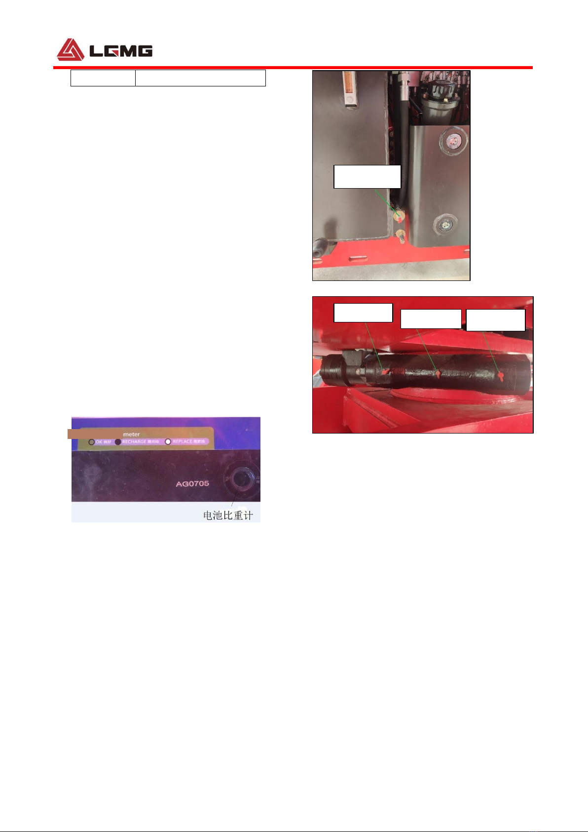
6) Position 3: Lubrication of the tapered roller
bearing: the tapered roller bearing is full
and does not need to be lubricated again.
1.3.2 Market Maintenance
1) Position I: Lubrication of the roller path:
2) Quantity: Proper amount (18g is
recommended)
3) Lubricating frequency: Lubricate every year
or every 1,000 h, whichever occurs first.
4) Lubrication method: Continuously inject
lubricating grease into the injection port of
lubricating grease while rotating the slewing
reducer
5) Model of the lubricating grease: 3#
lubricating grease
1) Position II: Lubrication of the engaging
position between the worm and the slewing
bearing
2) Quantity: Proper amount (It is suggested to
inject a total of 400g of lubricating grease)
3) Lubricating frequency: Lubricate every
three months or every 150 h, whichever
occurs first.
4) Lubricating method: Continuously inject
lubricating grease into the injection port of
lubricating grease while rotating the slewing
reducer
5) Model of the lubricating grease: 3#
lubricating grease
1) Position III: Lubrication of the tapered roller
bearing:
2) Quantity: Proper amount (5g is
recommended at each position, and a total
of 10g for the two positions)
3) Lubricating frequency: Lubricate every year
or every 1,000 h, whichever occurs first.
4) Lubricating method: Direct lubrication
5) Model of the lubricating grease: 3#
lubricating grease
1.4Check Hydraulic Oil Level
Check it every 8 hours or every day.
Maintaining the hydraulic fluid at the proper oil
level is essential for the vehicle operation. If the
hydraulic oil is at an appropriate oil level, the
hydraulic components may be damaged.
Through daily inspections, the inspector can
determine changes in the hydraulic oil level
which can indicate problems with the hydraulic
system.
1) Make sure the boom is in the telescoped
position and then visually check the
hydraulic tank.
Result: The hydraulic oil is above the middle
scale of the level gauge and below the
maximum scale of the level gauge.
2) The hydraulic oil should be filled as needed.
No over-filling will be allowed. Hydraulic oil
Specification
Use
temperature
Oil type
Remark
The lowest
temperature>
-25℃
L-HV32 Low
temperature
hydraulic oil
Chevron
-40℃<The
lowest
temperature≤
-25℃
L-HS32 Ultra
low
temperature
hydraulic oil
The lowest
temperature≤
-40℃
10# Aviation
hydraulic oil
1.5 Check for the Oil Level in
the Reducer
Check this step every 250 hours or a quarter.
The incorrect oil level in the reducer shall lead to
the reduction of equipment performance and
continuous use will result in damage to
components.
1) Drive the equipment rotating until a plug is
at the highest point.
2) Remove the other plug and check the oil
level.
Result: The oil level shall be the same as the

Maintenance Manual of Elevating Work Platform
6
bottom of the side plug hole.
3) When required, remove the upper plug and
refill oil until the oil level is the same as the
bottom of the side plug hole.
4) Apply the pipe thread sealant to the plug
and install the plug in the reducer.
5) Repeat this step for each reducer.
1.6 Replacement of the Gear
Oil of Reducer
It is available in the first 50 hours, and it will be
replaced every 1,000 hours or a year.
It is necessary to replace the gear oil of reducer
to maintain good equipment performance and
service life. Failure to replace the reducer
engine oil every year may result in reduced
equipment performance, and continuous use
may result in damage to components.
1) Select the reducer to be maintained, and
drive the equipment until one plug is at the
lowest point.
2) Remove the two plugs and drain the oil
(note to be drained) into the proper
container.
3) Drive the equipment rotating until a plug is
at the highest point.
4) Refill oil from the hole of reducer at the high
point until the liquid level is the same as the
side hole at the bottom. Install a plug.
5) Repeat this procedure for each reducer to
refuel.
1.7 Check for Engine Oil
Level
△
!Do not operate on running
engines! No smoking and open fires!
Be careful when contacting with high
temperature engine oil. Danger of
scalding!
△
!When operating on the oil system,
pay attention to the surface cleaning.
Carefully clean all areas involved. Blow
wet parts with compressed air.
△
!Please observe the safety
regulations for engine oil and relevant
local regulations. Dispose of spilled
engine oil and filter elements as
required. Waste oil cannot penetrate
into the ground.
△
!Test run shall be carried out after
each operation. At the same time, pay
attention to the sealing and lubricating
oil pressure, and then check the
engine oil level.
Check the engine oil level every 8 hours or
every day.
Insufficient or excessive engine oil may cause
damage to the engine. The engine oil level can
only be checked when the engine is placed
horizontally and closed. If the engine is hot,
close the engine and check the engine oil level
5 minutes later. Check it immediately if the
engine is cooled.
1) Insert the oil measuring rod and clean it
with a piece of clean and fiber-free cloth.
2) Insert the oil measuring rod into the bottom.
3) Pull out the oil measuring rod and read the
value of engine oil level.
4) The engine oil level shall always be
between MIN and MAX!
Fill up to the maximum liquid level if necessary.

Maintenance Manual of Elevating Work Platform
7
1.8 Replacement of Engine
Oil and Filter
△
!Do not operate on running
engines! No smoking and open fires!
Be careful when contacting with high
temperature engine oil. Danger of
scalding!
△
!When operating on the oil system,
pay attention to the surface cleaning.
Carefully clean all areas involved. Blow
wet parts with compressed air.
△
! Please observe the safety
regulations for engine oil and relevant
local regulations. Dispose of spilled
engine oil and filter elements as
required. Waste oil cannot penetrate
into the ground.
△
! Test run shall be carried out after
each operation. At the same time, pay
attention to the sealing and lubrication
oil pressure, and then check the
engine oil level.
It is available in the first 50 hours, and the
engine oil and filter shall be replaced every 500
hours. (If the ambient temperature continues to
be below -10℃. (14゜F) or the temperature of
engine oil is below 60℃(84゜F), or the sulphur
content in the diesel fuel is 0.5 - 1%, the oil
change period is reduced by a half; if the engine
oil does not reach the replacement interval
period within a year, the oil shall be replaced at
least once a year.)
△
!Danger of burn, be careful of
high-temperature engine parts and oil,
contacting with high temperature
engine oil and/or engine parts will
cause severe burns.
△
!Perform the function after engine
warm up to normal operation
temperature.
Replacement of engine oil
△
! After the filter element is replaced,
be sure to keep the engine idling at a
low speed for at least 3-5 minutes, so
that the engine has been lubricated
before being put into operation.
Figure 1-3
1) Warm up and run the engine.
2) Place the engine horizontally.
3) Shut down the engine.
4) Place the container under the engine oil
drain plug.
5) Screw off the engine oil drain plug to drain
the old engine oil.
6) Install the new seal ring for the engine oil
drain plug and screw in and tighten it.
7) Add engine oil at the engine oil filler.
8) Warm up and run the engine.
9) Place the engine horizontally.
10) Check the engine oil level and fill it if
necessary.

Maintenance Manual of Elevating Work Platform
8
Figure 1-4
Figure 1-5 Oil filter and oil drain plug
Replacement of the Engine Oil Filter
The engine oil filter element must also be
replaced every time the engine oil is replaced.
△
! Never fill the filter in advance.
There is risk of contamination.
1) If a torsion stopper is installed, remove the
clamping clamp (optional).
2) Release and unscrew the filter element with
a wrench.
3) Contain the oil that was drained.
4) Clean the sealing surface of the filter holder
with a clean fiber-free wiper.
5) Apply a thin layer of engine oil to the seal
ring of the new filter.
6) Screw in a new filter manually until seal fit
and tighten it with 10-12 Nm.
1.9 Check for Fuel Leakage
△
!The engine must be shut down!
No smoking and open fires!
Be careful when contacting high
temperature fuel!
Please observe the safety regulations for fuel
and relevant local regulations. Dispose of
spilled fuel and filter elements in accordance
with national regulations. The fuel cannot seep
into the ground.
Visually check for fuel leakage every 8 hours or
every day.
△
!There is danger of explosion and
fire. The fuel of the engine is
combustible. Check the position of the
machine. When this step is performed,
the machine should be in a well-
ventilated area away from the heater,
spark, flame, and burning tobacco. A
qualified fire extinguisher shall be
placed in an easily accessible place.
△
!There is danger of explosion and
fire. If fuel leaks, prevent any additional
person from entering the area or
operating the equipment. Repair the
leakage immediately.
1.10 Vent Fuel Pre-Filter
△
! Risk of explosion and fire. Engine
fuel is combustible. The position
where the equipment is located shall
be inspected. When the step is
executed, equipment shall be located
in an open and well-ventilated area that
keeps away from the heater, spark,
flame and burning tobacco. Aqualified
fire extinguisher shall be placed at the
location that is easily accessible.

Maintenance Manual of Elevating Work Platform
9
△
!Perform the step when the engine
flames out.
Figure 1-6
1. Fuel supply flow to the pump
2. Venting screw
3 .Electrical connection for water level sensor
4. Drain plug
5. Filter insert
6. Fuel inlet from the fuel tank
Check and drain the fuel filter every 8 hours or
every day.
1) Shut down the engine, and find the fuel
filter.
2) Disconnect cable connection.
3) Loosen the drainage plug located at the
bottom of the filter cartridge, allowing the
water drained to an appropriate container.
Once any fuel starts to flow out, screw
down the drainage plug immediately.
4) Wipe up any fuel that may be splashed.
5) Start the engine from the ground control
and inspect whether or not there is leakage
in the fuel filter.
Change the fuel pre-filter insert
1) Switch off the engine.
2) Shut off the fuel supply to the engine (with
high-level tank).
3) Place suitable collecting containers
underneath.
4) Disconnect cable connections.
5) Loosen drain plug and drain liquid.
6) Disassemble filter insert.
7) Clean any dirt of the opposite side of filter
head.
8) Wet the sealing surfaces of the filter
cartridge slightly with fuel and screw back
on to the filter head, clockwise (17-18 Nm).
9) Mount drain plug.
10) Open the fuel shutoff tap and vent the
system, see venting the fuel system.
Vent the fuel system
The fuel system is vented via the electric fuel
supply pump.
In order to ensure that no error messages are
generated, no attempt should be made to start
the system up whilst venting.
This process is carried out as follows:
● Ignition "ON"
The electronic fuel supply pump switches on for
20 seconds in order to vent the fuel system and
build up the required fuel pressure.
Wait until the electric fuel supply pump is
disconnected from the control unit.
● Ignition "OFF"
Repeat the process at least 2 times until the fuel
system is vented
△
! Risk of explosion and fire. Where there
is fuel leakage, prevent any irrelevant
personnel from entering the area and strictly
prohibit operating the equipment. Repair the
leak immediately.

Maintenance Manual of Elevating Work Platform
10
1.11 Replacement of the Fuel
filter
△
!The engine must be shut down!
No smoking and open fires!
Be careful when contacting high
temperature fuel!
△
!Do not release the injection
pipeline or the high-pressure oil
pipeline when the engine is running.
△
!Carefully clean all areas involved
in cleaning. Blow wet parts with
compressed air.
△
!Please observe the safety
regulations for fuel and relevant local
regulations. Dispose of spilled fuel and
filter elements in accordance with
national regulations. The fuel cannot
seep into the ground.
△
!After completing the operation on
the fuel system, exhaust the system,
perform the trial operation and check
the seal performance.
It is available in the first 50 hours, and
it will be replaced every 500 hours, or
half a year, but an increase in the
number of replacement filters is
required for the extremely dirty work
environment.
△
!There is danger of explosion and
fire. The fuel of the engine is
combustible. Check the position of the
machine.
When this step is performed, the
machine should be in a well-ventilated
area away from the heater, spark, flame,
and burning tobacco.
A qualified fire extinguisher shall be
placed in an easily accessible place.
△
!Never fill the filter in advance.
There is risk of contamination.
Figure 1-7
1) If a torsion stopper is installed, remove the
clamping clamp (optional).
2) Release and unscrew the filter element with
a wrench.
3) Contain the diesel fuel drained.
4) Clean the sealing surface of the filter holder
with a clean fiber-free wiper.
5) Apply a thin layer of diesel to the seal ring
of the new filter.
6) Screw in a new filter manually until seal fit
and tighten it with 10-12 Nm.
7) Fix the clamping clamp of a torsion stopper
(optional).
8) Exhaust the fuel system.
1.12 Check for Engine Air
Filter
Check the maintenance indicator for the air filter
every 8 hours or every day.

Maintenance Manual of Elevating Work Platform
11
△
!Perform this step when the
engine is turned off.
Figure 1-8
Check the maintenance indicator of the air filter
(If equipped). When the transparency of the
indicator turns red, filter element needs to be
maintained and cleaned or replaced.
Press the top of indicator to reset it, when the air
filter has been maintained.
1.13 Cleaning or
Replacement of Air Filter
Clean it every 250 hours or quarterly and
replaced it for every 1000 hours.
△
!Do not operate on running
engines!
△
!Be sure to pay attention to the
cleanliness of the external surface
when operating on the engine suction
system, and close the suction inlet
when necessary. The old filter
elements are handled in an
environmentally friendly manner.
Cleaning of air filter
△
!Do not clean the filter element (4)
with gasoline or high temperature
liquid.
If the primary element is stained heavily, replace
it soon. At this time, replace the secondary
element too.
The secondary element should be removed only
if it is to be replaced.
To protect the engine, do not remove the
secondary element in servicing the primary
element.
Figure 1-9
1. Air cleaner body
2. Dust cup
3. Secondary element
4. Primary element
5. Evacuator valve
Make sure the hooking clip for the element is
tight enough. If it is loose, dust and dirt may be
sucked in wearing down the cylinder liner and
piston ring earlier and thereby resulting in poor
power output.
Do not overservice the air cleaner element.
Overservicing may cause dirt to enter the
engine causing premature wear. Use the dust
indicator as a guide on when to service.
1) Open the hooking clip.
2) Remove the filter cover (2) and screw off
the filter element (4).
3) Filter element (4): For slight contamination,
purge with dry compressed air (maximum
205 Kpa) from inside to outside for cleaning

Maintenance Manual of Elevating Work Platform
12
(general cleaning times are no more than 5
times);
Replace it in case of serious contamination.
Replacement of the Safety Filter Tube of the
Air Filter
△
!Never clean the safety filter tube (3).
1) Screw off the Primary element (4) and the
Secondary element (3).
2) Install the new Secondary element.
3) Install the filter element (4), place the outer
cover (2) and fix it with the hooking clip.
1.14 Check for Coolant
Liquid Level
Check the coolant liquid level every 8 hours or
every day.
△
!The coolant at high temperature
has the risk of scald.
The cooling system is under pressure! The
cover can only be opened in the cooling state.
Coolant must have a specified concentration of
cooling system protectant!
Please observe the safety regulations for
coolant and relevant local regulations.
Dispose of the spilled coolant as specified,
without leaving it on the ground.
Never run the engine without coolant, even if it's
a very short time.
1) Carefully open the cover for the cooling
system.
2) The coolant liquid level shall always be
between min and max! Fill up to the
maximum liquid level if necessary.
1.15 Filling or Replacement
of Engine Coolant
Replace it every 2,000 hours or two years.
△
! The coolant at high temperature has
the risk of scald.
The cooling system is under pressure! The
cover can only be opened in the cooling state.
Coolant must have a specified concentration of
cooling system protectant!
Please observe the safety regulations for
coolant and relevant local regulations.
Dispose of the spilled coolant as specified,
without leaving it on the ground.
Never run the engine without coolant, even if it's
a very short time.
Draining of the Cooling System
1) Carefully open the cooler cover.
2) Place the receiving container under the
coolant interface.
3) Drain the coolant.
4) Reconnect and tighten the coolant
interface.
5) Close the cooler cover.
Filling of the Coolant
1) Carefully open the cover for the cooling
system.
2) Loosen the cooler exhaust bolts that may
be present.
3) Fill the coolant to max or the filling limit
position.
4) Open the possible heater and switch to the
maximum gear, to fill the heating circuit and
exhaust.
5) Close the cooler cover.
6) Run the engine to the running temperature.
7) Shut down the engine.
8) Check the coolant liquid level when the
engine is cooled, and fill it to max if
necessary.
△
! Note: The coolant with different
freezing point should be selected

Maintenance Manual of Elevating Work Platform
13
according to the local ambient
temperature, the principle is that the
freezing point of coolant is 10℃-15℃
lower than the local minimum
temperature.
1.16 Check for Engine Belt
Deutz-D2.9
Check it every 8 hours or every day.
△
! Only when the engine is stationary can
the belt drive operation be carried out.
△
!There is danger of burn. Be
cautious of high-temperature engine
components. Contact with them may
cause serious burn.
Belt Check
1) Visually inspect whether all belt drives for
damage.
2) Replace damaged components.
3) Reinstall the protector if necessary.
4) When it is a new belt, check whether the
position is correct. After running for 15
minutes, check the tension.
Replacement of belt
Figure 1-10
1) Loosen bolts (1,2,3) and nuts.
2) Move the engine in direction B, until the belt
is lose.
3) Remove the old belt, and install a mew one.
4) Move the engine in direction A until the
correct belt tension is reached.
5) Check the belt tension.
6) Tighten the bolts and nuts.
Tightening torque
Screw 1 42 Nm
Screw 2 30 Nm
Screw 3 M8 30 Nm
Screw 3 M10 42 Nm
1.17 Regular Maintenance
Maintenance items with period of a quarter, a
year, and two years must be completed by
qualified staff upon training in maintenance of
the machine in accordance with procedures in
the machine maintenance manual.
For machines that are idle for more than three
months, quarterly check must be performed
before they can be re-used.

Maintenance Manual of Elevating Work Platform
14
1.18 Engine fault table
Faults
Cause
Measures
Engine does not start or is
difficult to start
Not disconnected (if possible)
Check coupling
Engine does not start and
diagnostic lamp flashes
Fuel tank empty
Tanks
Fuel suction pipe blocked
Check
Below starting limit temperature
Check
Cold starting device
Check/replace
Wrong SAE viscosity class of the engine
lubricating oil
Change the lubricating oil
Fuel quality does not comply with
operating manual
Change the fuel
Battery defective or discharged
Check battery
Cable connection to starter loose or
oxidized
Check cable connections
Starter defective or pinion does not
engage
Check starter
Air filter clogged / turbocharger defective
Check/replace
Air in fuel system
Vent fuel system
Compression pressure too low
Check compression pressure
Exhaust gas backpressure too high
Check
Injection line leaks
Check injection line
High-pressure pump defective
Check/replace
Engine does not start and
diagnostic lamp flashes
Engine electronics prevents starting
Check error according to error code and
eliminate error if necessary
Engine starts, but runs irregularly
or fails
Exhaust gas backpressure too high
Check
Compression pressure too low
Check compression pressure
Cold starting device
Check/replace
Air in fuel system
Vent
Fuel filter contaminated
Clean
Fuel quality does not comply with
operating manual
Change the fuel
Injector defective
Change
Injection line leaks
Check injection line
Engine cable harness defective
Check/replace
Speed changes are possible and
diagnostic lamp lights up
Engine electronics has detected a system
error and activates an equivalent speed
Check error according to error code and
eliminate error if necessary
Engine becomes excessively
hot.
Temperature warning system
activates
Vent line blocked
Clean
Lube oil cooler defective
Check/replace
Lube oil filter contaminated on the air or
lube oil side
Change
Lube oil level too high
Check lube oil level, if necessary drain
off.
Lubricating oil level too low
Fill up lube oil
Injector defective
Change
Coolant heat exchanger soiled
Clean
Defective cooling water pump (torn or
loose V-belt)
Check whether torn or loose

Maintenance Manual of Elevating Work Platform
15
Low coolant
Fill up
Resistance in cooling system is too high /
flow volume too low
Check the cooling system
Fan / viscous coupling defective, V-belt
torn or loose
Check/replace/tension
Charge air line leaking
Check charge air line
Charge air cooler soiled
Check/clean
Air filter clogged / turbocharger defective
Check/replace
Air filter maintenance switch /
maintenance indicator defective
Check/replace
Fan defective/V-rib belt torn or loose
Check fan/V-belt, change if necessary
Exhaust gas backpressure too high
Check
Throttle valve defective
Check/replace
Coolant temperature transmitter
Check/replace
Coolant thermostat defective
Check/replace
Coolant cover defective
Check/replace
Engine output is deficient
Lube oil level too high
Check lube oil level, if necessary drain
off.
Fuel suction temperature too high
Check the system
Fuel quality does not comply with
operating manual
Change the fuel
Air filter clogged / turbocharger defective
Check/replace
Air filter maintenance switch /
maintenance indicator defective
Check/replace
Fan defective/V-rib belt torn or loose
Check fan/V-belt, change if necessary
Charge air line leaking
Check charge air line
Charge air cooler soiled
Clean
Injection line leaks
Check injection line
Injector defective
Change
Throttle valve defective
Check/replace
Exhaust gas recirculation, actuator
defective
Check/replace
Exhaust gas backpressure too high
Check/clean
Exhaust gas turbocharger defective
Change
Engine performs poorly and
diagnostic lamp lights
Engine electronics reduce performance
Please contact your LGMG partner
Engine does not run on all
cylinders
Injection line leaks
Check injection line
Injector defective
Change
Compression pressure too low
Check compression pressure
Engine cable harness defective
Check/replace
Engine lubricating oil pressure is
nonexistent or excessively low
Lubricating oil level too low
Fill up lube oil
Excessive inclination of engine
Check engine mounting / reduce
inclination
Wrong SAE viscosity class of the engine
lubricating oil
Change the lubricating oil
Lubricating oil pressure sensor defective
Check/replace
Lubricating oil control valve jammed
Check/clean
Lubricating oil suction pipe blocked
Check/clean
Other manuals for AR16J
1
Table of contents
Other LGMG Lifting System manuals
Popular Lifting System manuals by other brands

AFFORDABLE LIFTS
AFFORDABLE LIFTS KCSPM3648 Assembly and installation manual

Avanti
Avanti SHARK L AECO Original instructions

Paragon Pro
Paragon Pro Telpro The Troll 112 manual

morse
morse 400A-72-117 Operator's manual

Summit
Summit SUM-905225 Operation manual

probst
probst TAS-UNI Translation of original operating instructions

HENNESSY INDUSTRIES
HENNESSY INDUSTRIES coats 4TV21NSR1 manual

Mohawk
Mohawk TP-20 manual

Nexus 21
Nexus 21 AL-125 installation instructions

HADEF
HADEF 208/05 Installation, Operating and Maintenance Instruction

Manitou Systems
Manitou Systems 160 ATJ Operator's manual

Bestcare
Bestcare BESTLIFT PL400EF manual