2
SAFETY
REFUELING SAFETY
Never smoke near the machine during refueling.
Donotpermitanyonetobeonthemachineduring
refueling.
Spilled fuel must be cleaned up, completely
absorbed or evaporated before starting the
engine.
Make sure the fuel cap is in place before starting
the engine.
Never use an open flame when checking the fuel
level in the tank.
Never fill the fuel tank with the engine running.
Make sure you have adequate ventilation during
fueling.
OPERATOR QUALIFICATIONS AND
TRAINING
Only trained and authorized persons should
operate and service the machine. To be qualified,
you must understand the written instructions
supplied by the manufacturer, have training
(including actual operation of this machine) and
know the safety rules and regulations for the
jobsite. A self-training course available from the
Mason Contractors Association of America is
highly recommended.
Lull has produced an operational safety video that
is available on VHS tape. This video shows safe
operating and maintenance practices for your
forklift. A copy this video is shipped with each new
machine. You can also contact your Lull
authorized dealer to obtain a copy.
Do not operate the machine until you fully
understand the function of all controls, indicators
and instruments.
PERSONAL SAFETY
Wear all the protective clothing and personal safety
devices issued to you or called for by job conditions.
You may need…
WA hard hat
WSafety shoes
WSafety glasses, goggles, or face shield
WHeavy gloves
WHearing protection
WReflective clothing
WWet weather gear
WRespirator or filter mask
Avoid entanglement hazards. Do not wear
clothing or jewelry that could catch on machinery.
Keep your hands, hair, feet and clothing away
from moving parts. Always keep your hands and
feet inside the cab.
Know the pinch points and rotating parts on the
machine.
Always know where to get assistance in case of
an emergency. Know how to use a first aid kit and
fire extinguisher.
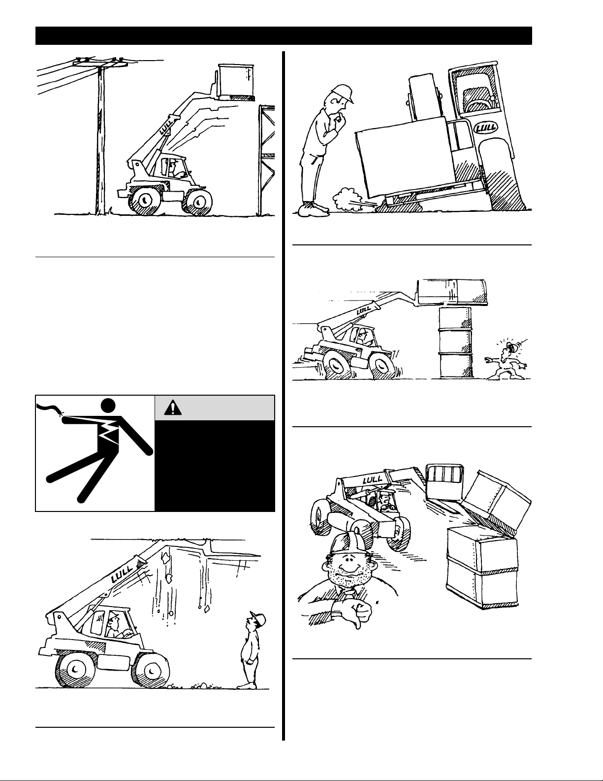
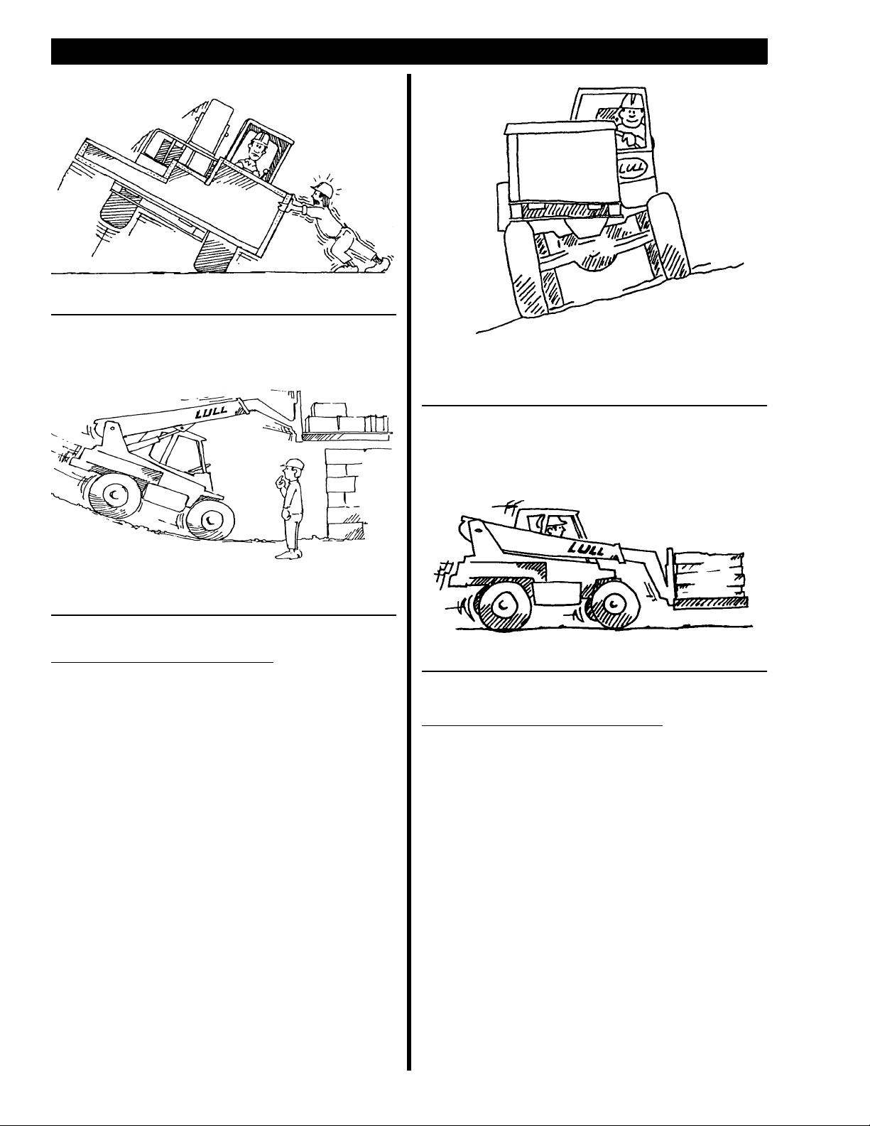
MACHINE STABILITY
Your Lull rough terrain forklift is proven to be stable
when properly operated. However, improper operation,
faulty maintenance, unauthorized modifications, or poor
housekeeping may cause instability.
Some Conditions that Affect Stability:
WGround and surface conditions.
WSurface grade.
WWeight and configuration of the attachment.
WImproper tire inflation.
WOperator judgement.
WExcessive tilting of the fork carriage or other
attachmentswithanelevatedloadcancause
machine instability. The amount of allowable tilt is
governed by conditions such as boom elevation,
weight of load, and terrain.
STARTING SAFETY
Before Starting the Engine…
Important: Warn all others in the area that you are
going to start the forklift.
1. Check underneath and around the machine and
make sure all personnel are clear.
2. Be properly seated.
3. Set the park brake.
4. Make sure shift selector is locked in the
NEUTRAL position.
5. Apply the brakes.