Lumag BSW66GL User manual

Distribution Limited
Petrol Band Saw Mill
Operator’s Manual
BSW66GL
FOR YOUR SAFETY
READ AND UNDERSTAND THE ENTIRE MANUAL
BEFORE OPERATING THIS MACHINE


!
2!
GENERAL SAFETY RULES ---------------------------------------------------- 3
DESCRIPTION OF THE SAWMILL------------ ------------------------------ 4
SAFETY INSTRUCTIONS ----------------------------------------------------5
SAWMILL ASSEMBLY INSTRUCTIONS ----------------------------------- 9
SAWMILLSET-UPPROCEDURES-------------------------------------------18
LOAD AND LOCK LOG/CANTS ON THE BED-------------------------- 24
BLADE SLIDABLE GUARD ADJUSTMENT ----------------------------- 25
CUTTING HEIGHT ADJUSTMENT ------------------------------------------27
HOW TO RELEASE THE SAW BLADE ------------------------------------27
RUN YOUR SAWMILL ----------------------------------------------------------28
SAWMILL MAINTENANCE ----------------------------------------------------29
TROUBLESHOOTING ----------------------------------------------------------30
SPECIFICATION-----------------------------------------------------------------31
EC DECLARATION ------------------------------------------------------------ 32
Contents

!
3!
Thank you very much for choosing the Lumag Portable Sawmill.
For future reference, please complete the owner’s purchase date: __________
Save the receipt for warranty and these instructions.
It is important that you read the entire manual to become familiar with this product before you begin using it.
This machine is designed for certain applications only. We strongly recommend this machine is not modified and/or
used for any application other than that for which it was designed. If you have any questions relative to a particular
application,
DO NOT use the machine until you have first contacted us to determine if it can or should be performed on the product.
For technical questions and replacement parts, please contact the dealer where you buying it.
INTENDED USE
This sawmill is designed for sawing logs w/out branches while the mill is firmly supported on the ground. There are
holes on the feet. Please make sure to fix the feet with screws to solid ground.
For your own safety and the safety of others, does not use the band sawmill or handle band saw blades without
first reading through and understanding the contents of this user manual in their entirety.

!
4!
DESCRIPTION OF THE BAND SAWMILL
N
H
A. Saw carriage
B. Crank for adjusting cut depth
C. Adjustable blade guard
D. Lever & throttle control
E. Log support
F. Log clamp (hidden behind)
G. Log bed
H. Safety switch
I. Band wheel guard
J. T-handle for saw blade tensioning
K. Fluid reservoir for saw blade cooling
L. Plug
M. Lifting points on the saw carriage
N. Rail end stop
O. Support leg
P. Motor/petrol engine
Q. Electric box

!
5!
SAFETY INSTRUCTIONS
Key to symbols
Warning! This symbol means that you have to take particular care. It is always accompanied by information on
the specific risk.
ATTENTION. Pay extra attention when this symbol appears in the text. It will be followed by an admonition or a
warning.
For your own safety and the safety of others, do not use the bandsaw mill without first reading through and
understanding the contents of this user manual in their entirety.
Warning! Cutting tool: Careless use of the machine can result in potentially fatal injuries. Bandsaw blades are
extremely sharp and dangerous.
Always wear protective gloves when working with the bandsaw mill. Risk of sustaining cuts when handling
bandsaw blades. Bandsaw blades and motor/engine parts may be hot after sawing.
Always wear approved ear protection when working with the machine. Even brief exposure to high frequency
noise can damage your hearing. Always use close-fitting protective eyewear when working with the machine or
handling bandsaw blades. Under certain circumstances the use of a protective mask may also prove beneficial.
Always wear approved protective footwear with saw protection, steel toe-caps and nonslip soles when working
with the machine.
Always wear full-length protective trousers when working with the machine. Never wear loose-fitting clothing,
scarves, necklaces, etc., that may get trapped in the machine during the work. Tie up long hair before working
with the bandsaw mill.
Always wear approved protective glasses when working with the machine
Always wear approved protective face mask when working with the machine
Operator
Warning! Whenever the machine is used, approved personal protective equipment must always be used. Personal
protective equipment does not eliminate the risk of injury, but it can reduce the effects of an injury in the event of any
near-accident.
Persons under 18 must not use the bandsaw mill or handle bandsaw blades.
Never use the machine or handle bandsaw blades if you are tired, have consumed alcohol or are taking medicine
that might affect your sight, judgment or control over your body.
Warning! Never operate a bandsaw mill with a combustion engine in an enclosed or poorly ventilated area. This
can cause death by asphyxiation or carbon monoxide poisoning.
If fully adequate working lighting is not available, only use the bandsaw mill in full daylight.
Keep the workplace free of debris, pets,children, obstacles and anything else that may distract the operator.
Choose an erection site where the supporting ground is tightly compacted and level, with generous space for the
bandsaw mill, log piles and sawn wood. The machine can be only used in level surface. Please fix the track feet on
cement slabs or wooden blocks (15 cm x15 cm).
Always have a hand-held fire extinguisher of ABC type (min. 3 kg) readily accessible at the workplace.
Take precautions to reduce the hazard of inhalation of harmful dusts (e.g. wearing a dust mask)

!
6!
Always have a complete first aid kid available at the workplace.
The machine must be installed with a residual current device.
The machine can be only used outdoor.
Using the bandsaw mill
Warning! Cutting tool: Always stand behind the saw carriage and keep both hands on the handle when operating
the machine. Never stand in front of the saw carriage or bandsaw blade. Never pull the saw carriage through a cut.
Warning!Never clean the saw blade or band wheel of a band saw using a hand-held brush or scraper whilst the saw
blade is in motion
Warning!Use suitable carrier equipment for transporting tensioned wide saw blades.
Warning!Never use the machine unless all guards and other safety devices necessary for machining are in good
working order. Check the function of the hold-to-run handle before every shift, if failed, must replace immediately.
Warning! Risk of entrapment and rotating parts: Even slight pressure on the saw head release mechanism can
cause the saw head to drop in an uncontrolled manner and the crank to start rotating at speed, which may result in
injury.
Warning! The clutch mechanism is very sensitive. Just slight pressure on the control when the engine is running
can engage the clutch and cause the bandsaw blade to move.
Warning! Never make modifications to this machine that result in it no longer conforming to the original version, and
do not use it if it appears to have been modified by others. Never use any accessories apart from those that are
recommended in this user manual.
Warning! A broken bandsaw blade can eject bandsaw blade fragments at high speed via the chip ejector. Make
sure that no one is at the side of the bandsaw mill when working. The risk of bandsaw blade breakage increases if
it has not been properly fitted or maintained.
Warning! In case of broken band or belt if fitted, the wheels may keep running, and it is necessary to wait for the
complete standstill of the machine before opening the guard(s);
WARNING: Do not cut lumber with foreign objects init such as nails, any metal pieces, etc.
The machine only can be used in weather conditions: temperature 5-40°C, and humidity 50%@40°C or 90%@20
°C and altitude less than1000m.
Make sure the machine has been properly assembled and maintained in line with the enclosed assembly
instructions as well as these instructions.
Never work alone. Always make sure there is another adult within hearing distance in case you need to call for help.
Never stand between a log pile and the bandsaw mill. Always stand to the side of the log pile when handling the logs.
Never stand where there is a risk of a log falling on you.
Warning! Adjust the adjustable saw blade guard as close to the workpiece as practicable.
Careful adjustment and regular maintenance of saw blade and band wheel cleaning equipment and of the
lubricating system will ensure that the residues do not build up.
Hazard area:
The minimum safe distances around the bandsaw mill:

!
7!
The safe distance on the bandsaw’s left side is 15 m, as there is a risk of saw blade fragments being ejected via the
chip ejector in the event of saw blade breakage. The extent of the hazardarea on the other sides is 5 m.
Warning! Keep your hands, arms, legs and other parts of your body well away from the bandsaw blade, cables and
other moving parts. Remember that when the saw carriage is moved, the position of the bandsaw blade and cable
also changes.
Warning! Risk of impact from the saw carriage.
Warning! Risk of tripping on rail and crossbars. Never take a short cut over the rail.
Warning! Hang electric cables up out of the way so that they do not get damaged or become a trip hazard.
Warning! Never operate the combustion engine in enclosed areas. Ensure good ventilation. The exhaust gases
contain harmful substances that are potentially fatal.
Warning! Risk of entrapment between sawmill and logs when loading.
Never climb onto the rail or the log bed crossbars.
Before each occasion of use:
Check that:
• the operator is wearing the prescribed personal protective equipment
• maintenance as prescribed has been carried out
• the bandsaw blade is stationary
• the machine has been erected so that it is stable and the rail is supported along its entire length
• the saw carriage’s anti-tip wheels and the rail’s end stops are in place
• all components on the bandsaw mill are tight and serviceable
• all the safety equipment on the machine is in place and working
• the bandsaw blade is properly installed and runs freely in the right direction
Before each cut:
Check that:
• no other persons or pets are within the hazard area of the machine
• the workplace is free of obstacles that might present a trip hazard or act as a distraction
• the bandsaw blade runs clear of the log supports and log clamps for the workpiece
• the rail is free of debris, dirt, etc.
• the workpiece is properly fixed in place
• the adjustable saw blade guard has been correctly set for the maximum width of the workpiece
When in use:
Warning! Risk of burn injury. The engine and its silencer become very hot both during operation and for a time

!
8!
after shutdown. This also applies when the engine is idling.
Warning! Risk of fire. Petrol and petrol vapours are highly flammable. Remember the fire, explosion and inhalation
risks involved.
Warning! Fire risk. The engine must have been shut down and allowed to cool for 10 min before fuel is added.
Always shut down the combustion engine when you leave the operator station, even if just for a short time, to deal
with sawn wood or perform maintenance.
When the machine is not in use, for example at the end of a shift, release the saw blade strain
Warning! Short circuit. Perform regular checks to ensure that the battery cables are not damaged. Make sure that
no metal parts come into contact with the battery terminals.
Long-term storage
The band saw blade should be taken out of the machine, coiled, secured and stored in a safe, dry place that is not
accessible to children or other persons even during short periods of non-use.!Before next use, the bandsaw blade should
be checked for damaged teeth and cracks;
When stored for longer periods the following applies:
- empty the fuel tank and coolant reservoir, - remove the bandsaw blade from the machine, - close the fuel valve, - lock
the saw carriage in position. Store the bandsaw mill in a place that is not accessible
to children or other persons, preferably in a locked room.
Only store the machine in the place with a condition temperature at 25 to +55°C
Only transport the machine in weather conditions at 25 to +55°C
Maintenance
Warning! Before performing servicing or maintenance on the machine: - remove the spark plug on the engine or
unplug the electric cable of the motor.
Warning! Risk of burn injury. The engine and its silencer become very hot both during operation and after shutdown.
Allow the engine and silencer to cool before performing servicing or maintenance on the machine.
Warning! Never try to dismount the fixed guard! The fixed guard can be only dismounted by the manufacturer for
maintenance (replace saw band or belt etc.) or cleaning.
Moving the bandsaw mill
Warning! Risk of entrapment. Keep persons and animals outside the 5 m hazard area around the machine when
lifting and moving machine parts. Secure the load during transport.
The saw carriage and rail component must not be lifted or transported while assembled, but must be transported
separately.
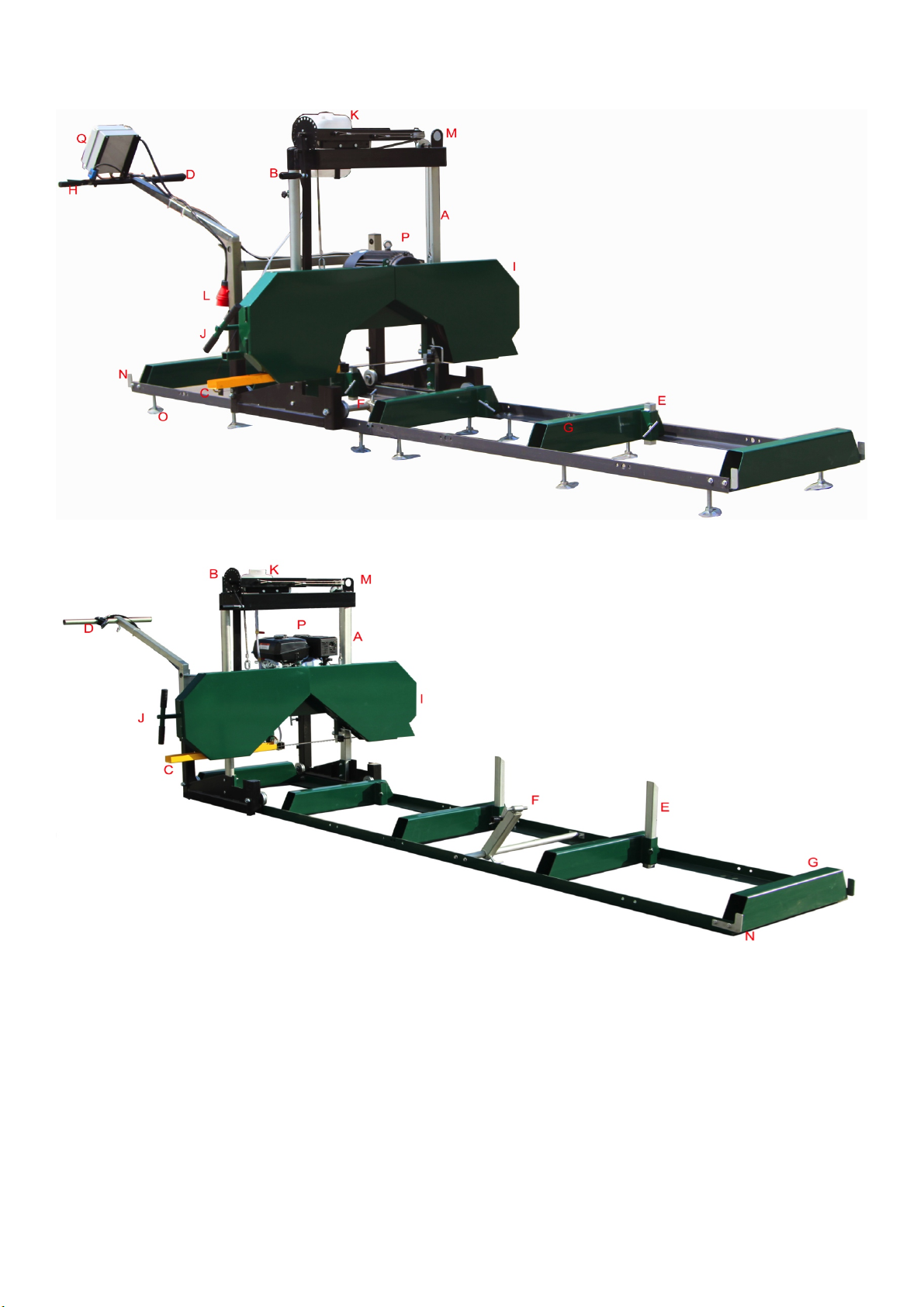
Lifting the saw carriage: Lift the saw carriage using the lifting points right at the top.
Weight, see Technical data.
Lifting the rail component: Use pallet forks or a fork lift to lift the rail from below. Place a protective layer of wood
material on the forks before lifting. Make sure that the rail component is well balanced and secure the load to the pallet
fork before transporting it. Weight, see Technical data.
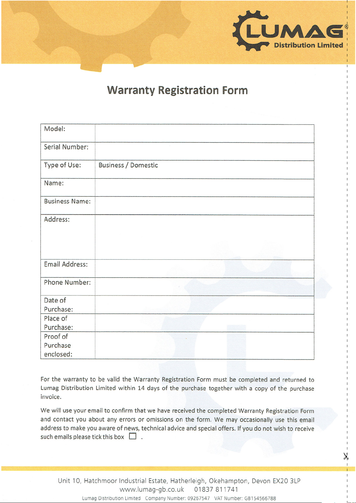
SAWMILL ASSEMBLY

!
9!
#1 – INSPECTION
Take all of the parts out of the shipping crate and lay them out. Check for any damage or missing parts.
#2 – TRACKS
Assemble track system and secure loosely with provided nuts & bolts. It is important not to fully tighten the bolts at this
stage. This will be done after the head is assembled and rolled along the track. It is ideal to assemble the tracks on a
solid and level footing that is a minimum of 4” off of the ground. This will allow for easy cleanup of sawdust from under
the tracks and height adjustment of the log supports.
Attach track cross supports to “L” channel with the provided nuts & bolts. The joining plate(assembled under two rails)
is used at the seam joint to join the two sections together (shown in right images). Ensure to only hand tighten at this
stage. The bolts will be fully tightened once the head assembly is free to roll on the tracks and provide the correct track
width.
Assemble carriage stops at the ends of the tracks (4 stops total) and tighten.
#3 – LOG DOG & SUPPORTS

!
10!
Assemble log dog pieces as shown below and use waterproof grease on threaded handle and “T” handle. Attach
assembly to the track using the provided nuts & bolts and tighten.
Attach log dog assembly to track as shown above with the 4 nuts and bolts provided. Note that there are various
locations along the track where this assembly can be bolted. Depending on how many track sections are being used,
select a log clamp position that will secure the log firmly against the log supports.
Insert log supports into track cross supports and secure with “T” handles. The “T” handle threads should be coated with
waterproof grease. The sawmill includes two sets of log supports – a short set and a long set. The longer set is ideal for
larger logs and the shorter set is ideal for small logs and square cants.
#4 – CARRIAGE ASSEMBLY
Clamp!for!
large!log!
Clamp!for!small!
logs!&!cants!

!
11!
Lay the above carriage pieces out.
Assemble round vertical post (shown on left) to wheel assembly using the two bolts and back plate. Repeat same step
for the square vertical post assembly (shown on right).
Place a moving blanket on the shipping pallet that the sawmill crate was strapped to. The blanket will prevent the blade
guard covers from becoming scratched. Using a minimum of two people or a mechanical advantage system, remove
the head assembly from the sawmill crate and place face down on the blanket. The head assembly is very heavy,
proper technique must be used to avoid injury or damage.
Insert vertical post assemblies into corresponding locations in head assembly as shown above.

!
12!
Insert the rear square frame into the carriage base until it bottoms out on the pulley bolts. Tighten the four 16mm bolts
(shown in right image) to secure it in place.
Lock the cam handles on both the round and square post to prevent the head from moving when it is stood up in the
coming steps. Ensure that when activating the cam handles, the clamps securely lock on the round and square vertical
post. If they don’t, a 13mm wrench will need to be used to tighten the adjustment nut. This will allow the clamps to lock
on the post better.
With one person on each post, stand the head assembly up on the wheels as shown above. Again, using a minimum
of two people, set the saw head assembly on the track system ensuring the carriage wheel grooves rest on the “L”
rails. The square vertical post should be on the same side as the log supports.
Slide the top cross support over the round post and insert the pulley, collar and bolt assembly into the hole.
Adjustme
nt!nut!

!
13!
Install the nut on the inside of the round post to secure the pulley. Using a 16mm wrench to hold the nut, tighten the
bolt.
Insert the bolts into the back plate as shown in above left image. Align the square post holes with the corresponding
black top cross support holes. Tighten using an 18mm socket.
Place the measuring scale bracket as shown above and insert bolts and nuts. It is important to alternate tightening of
the nuts (top then bottom) to ensure the black round clamp begins to compress evenly on both the top and bottom until
flanges meet at outer edge. Tighten nuts using a 13mm socket.
Install the square indicator rod to the sawmill using the two bolts and tighten using a 10mm socket.

!
14!
Slide the scale indicator over the square rod and tighten.
Install the cables to the pulleys as shown above.
Attach the cable bolts to the brackets on the sawmill head as shown above. It is ideal to lower the sawmill head all the
way down to the deck. Once this is done, adjust the two bolts so that the sawmill head is level to the track cross
supports. See next page for further details on this set up.

!
15!
Using a tape measure, take a measurement from the blade to the top of the log bunk on both the left and right side. The
distance should be equal on both sides. If it isn’t, you need to adjust the cable bolts (shown on page 13) up or down to
raise or lower the head on one side until themeasurement is consistent on both sides.
Insert the H-type handle piece into the carriage vertical posts. Insert the “L” handle to the right vertical post. Adjust the
height of the handles and lock them with the T-bolts. Please refer the above picture.
Connect the lock-pin cable to the guiding-wheel-locking-handle.Fix the cable to the L- handle with the 3 nylon ties.
To make sure the engine can run at the highest speed when the throttle handle is fully pushed down. To make sure the
guiding wheel can running smoothly when the guiding wheel locking handle is pushed down.
Put the lube tank to the bracket. Insert the lube tank line through the hole in the bottom of the saw head as shown
above. Use a 16mm socket to secure the copper end in position. Do not over tighten or crush the copper end.
H-Type!handle!
“L”handlecpl.!
H-Type!handle!
“L”handlecpl.!
Lock-pin!cable!

!
16!
Use the tap at the water tank to adjust the liquid flow by turning the screw left and right.
Attach the four track sweepers to the frame so that the steel brush reaches the bottom of the groove in the carriage
wheels. Use a 13mm socket to fasten.
Add waterproof grease to the threads of the blade tension “T” handle and to the washer face that it meets before use.
USA a 24mm socket on a torque wrench to tighten the “T” handle to 25 N.M torque to achieve proper blade tension.
See above right image.
*Note – It is very important to take the tension off of the blade by turning the “T” handle in the
counter-clockwise direction when the sawmill is not in use and hangs the below notice to the “T” handle.
Failure to do so, will result in flat spots on the rubber belts. These flat spots will cause the mill to vibrate
excessively during next use.*
Add waterproof grease to all “T” handle threads on the sawmill.
24mm!
NOTICE!
CHECK THE
TENSION OF THE
BAND SAW BLADE
BEFORE CUTTING!!

!
17!
Push the saw head up and down the track system to ensure that the width of the track allows for the saw head to move
freely. If it binds, the “L” rails will need to be set further or closer together to achieve a consistent width along the entire
track system. Once the desired width is achieved, all nuts and bolts can be tightened to the log bunks as shown in
above right image using a 16mm socket.
#5 – ENGINE
Refer to the engine manual before using your sawmill. Please note that the engine does not contain any gasoline or
engine oil when it is shipped. Furthermore, the engine is equipped with an oil alert system, meaning that if the
crankcase oil level is low or empty, the power is cut to the spark plug and it will not start.
Always cut in the direction shown above. The log clamp should always be on the right side of the log and the log
supports should always be on the left. Failure to cut in this direction can cause the log to come lose and possibly even
cause damage or injury.
*Now that your sawmill is assembled, please run through the “SAWMILL SET-UP PROCEDURES” in the
following section. Failure to do so may result in poor sawing performance, damage or injury. See next page. *
Left!side!of!Sawmill!
Right!side!of!Sawmill!

!
18!
SAWMILL SET-UP PROCEDURES
#1 – BELT TENSION
To check the belt tension, with a tension meter, deflect the belt up and down with 60N force. There should be no more
than 5-6mm of deflection in both directions. If the belt deflects more than this, it will need to be tightened as described
below.
To tighten the drive belt, start by loosening the four bolts that secure the engine to the engine mount using a 16mm
wrench.
Now that the engine is free to slide on the engine mounting plate, turn the 16mm nut on the horizontal stud in the
clockwise direction. This will pull the engine towards the stud and apply more tension on the belt. Do this step
incrementally while checking the belt for proper deflection. It is also important to ensure that the engine remains
perpendicular to the drive belt. Over tightening can cause the engine to twist on the mounting plate, resulting in belt
alignment issues and premature wear. Once the desired belt tension is set, tighten the four engine bolts.
Alternatively, if the drive belt is too tight, the 16mm nut on the horizontal stud can be turned counter-clockwise.

!
19!
#2 – BLADE TRACKING
Never attempt the below with the engine running. As a safety precaution, remove the spark plug cap. It is also advised
to wear gloves and safety glasses when working with the blade, as it is extremely sharp.
The blade should run with the same tooth to bandwheel face distance on both sides. 9.5mm is ideal. Measure the
distance from the tip of the blade tooth to the front face of the bandwheel on both sides. If an adjustment on either side
is required, the below steps will detail this procedure.
Loosen the blade guide assembly bolt with a 16mm socket. The round shaft should now be free to slide rearward and
out of the way. Perform this step on both guide assemblies. This will ensure that the guide bearings do not influence
tracking of the blade while adjusting.
Take some tension off of the blade by turning the “T” handle in the counter-clockwise direction one full turn from full
tension position.
Loosen the tracking alignment locking nut.
9.5mm!
Rearward Direction
!
Forward Direction
!
Table of contents
Other Lumag Saw manuals