Lumag WS600 User manual

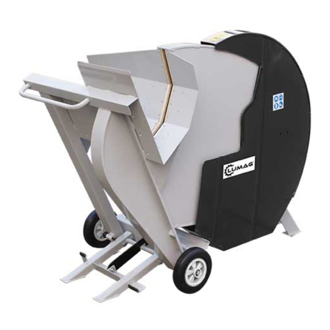
Manual For Log Saw
WS600
230V/50HZ
For Your Safety
Read And nderstand The Entire Manual Before Operating Machine.
Save This Manual For Future Reference

1. Proper use
The firewood drag saw is designed for cross-cutting firewood within the specified dimensions (see
technical data) in a feed cradle that pivots towards the saw blade. This tool is only designed for
outdoors use and for operation by one person. Other persons must remain a safe distance away from
the tool whilst it is operating.
The machine is to be used only for its prescribed purpose.
Any other use is deemed to be a case of misuse.
The user/operator and not the manufacturer will be held liable for damage and/or injuries of any kind
that result from such misuse. The machine is to be operated only with suitable saw blades (saw
blades made of HM or CV). It is prohibited to use any type of HSS saw blade and cutting-off wheel.
To use the machine properly you must also observe the safety regulations, the assembly instructions
and the operating instructions to be found in this manual.
All persons who use and service the machine have to be acquainted with this manual and must be
informed about the machine’s potential hazards. It is also imperative to observe the accident
prevention regulations in force in your area.
The same applies for the general rules of occupational health and safety.
The manufacturer shall not be liable for any changes made to the machine nor for any damage
resulting from such changes.
Even when the machine is used as prescribed it is still impossible to eliminate certain residual risk
factors. The following hazards may arise in connection with the machine’s construction and design:
•Contract with the saw blade in the uncovered saw zone.
•Reaching into the running saw blade (cut injuries).
•Kick-back of work-pieces and parts of work-pieces.
•Saw blade fracturing.
•Catapulting of faulty carbide tips from the saw blade.
•Damage to hearing if ear-muffs are not used as necessary.
•Harmful emissions of wood dust when used in closed rooms.
2. Important information
Please read the directions for use carefully and observe the information provided. It is important to
consult these instructions in order to acquaint yourself with the machine, its proper use and safety
precautions.
Safety information
•Warning: When using electric tools it is imperative to take the following basic safety precautions in
order to reduce the risk of electric shock, injury and fire.
•Take due note of all this information before and while working with the saw.
•Do not lose these safety regulations.
•Guard against electric shock
Avoid body contact with earthed parts.
•When equipment is not being used it should be kept in a dry, closed place out of children’s reach..
•Keep mounted attachments sharp and clean to enable you to work well and safely.
•Check the power cable regularly and have it replaced by an authorized specialist at the first sign of
any damage.
Check your extension cables regularly and replace them if damaged.
•When working outdoors, use only extension cables that are approved for outdoor use and which are
marked accordingly.
2

•Concentrate on what you are doing. se common sense when working. Do not operate the tool if
your mind is not on your work.
•Never use an electric tool with a switch that cannot be turned on and off.
•Warning! The use of other tools and accessories may put you at risk of injury.
•Always pull the plug out of the power socket before adjusting or servicing the machine.
•Give these safety regulations to all persons who work on the machine.
•Caution! Hands and fingers may be injured on the rotating saw blade.
•The machine is equipped with a safety circuit-breaker (7) to prevent it starting up again after a
voltage drop.
•Before you use the machine for the first time, check that the voltage marked on the rating plate is
the same as your mains voltage.
•If you need to use extension cable, make sure its conductor cross-section is big enough for the
saw’s power consumption. Minimum cross-section 1.5 mm² or 2.5 mm ²for cable lengths of 20 m or
more.
•If you use a cable reel, the complete cable must be pulled off the reel.
•Check the power cable. Never use a faulty or damaged power cable.
•Do not use the cable to pull the plug out of the socket. Protect the cable from heat, oil and sharp
edges.
•Do not leave the saw in the rain and never use it in damp or wet conditions.
•Provide good lighting.
•Do not saw near flammable liquids or gases.
•Wear suitable work clothes! Loose garments or jewelry may become caught up in the rotating saw
blade.
•Non-slip shoes are recommended when working outdoors.
•Wear a hair net if you have long hair.
•Avoid abnormal working postures.
•Operators must be at least 16 years of age.
•Keep children away from the machine when it is connected to the power supply.
•Keep your workplace clean of wood scrap and any unnecessary objects.
•An untidy work area invites accidents.
•Do not allow other persons, especially children, to touch the tool or cable. Keep them out of your
work area.
•Persons working on the machine should not be distracted.
•Note the direction of rotation of the motor and saw blade. se only blades whose permissible
maximum speed is not lower than the maximum spindle speed of the circular saw and of the material
to be cut.
•After you have switched off the motor, never slow down the saw blade (7) by applying pressure to its
side.
•Only fit blades (7) which are well sharpened and have no cracks or deformations.
•Do not use circular saw blades (7) made of high-alloy high-speed steel (HSS).
•Only use saw blades that are recommended by the manufacturer, comply with EN 847-1 and bear a
warning note. When replacing the saw blade ensure that the cutting width is no smaller and the basic
blade thickness of the saw blade is no larger than the thickness of the splitter.
•Faulty saw blades (7) must be replaced immediately.
•Never use saw blades which do not comply with the data specified in this manual.
•Never dismantle the machine’s safety devices or render them inoperative.
3

•If the table insert is worn, replace it.
•Always stand to the side of the saw blade when working with the saw.
•Never load the machine so much that it cuts out.
•Make sure that off-cuts do not catch on the saw blade crown. Risk of catapulting!
•Never remove loose splinters, chips or jammed pieces of wood when the saw blade is running.
•To rectify faults or remove jammed pieces of wood, always switch off the machine first. Pull the
power plug!
•If the sawing gap is worn, replace the table insert. Pull the power plug!
Carry out retooling work, adjustments, measurements and cleaning jobs only when the motor is
switched off. Pull the power plug!
•Before switching on, make sure that all keys and wrenches have been removed from the tool.
•Switch off the motor and pull the power plug before you leave the workplace.
•Refit all guards and safety devices immediately after you have completed any repairs or
maintenance work.
•Be sure to observe the safety information and operating and maintenance instructions issued by the
manufacturer, as well as the dimensions listed in the Technical Data.
•It is imperative to observe the accident prevention regulations in force in your area as well as all
other generally recognized rules of safety.
•Note the information published by your professional associations (VBG7j).
•Do not use any low-powered machines for heavy duty work.
•Do not use the cable for purposes for which it is not designed.
•Make sure you stand squarely and keep your balance at all times.
•Check the tool for damage.
•Each time before re-using the tool, carefully check that the guards or any slightly damaged parts are
working as intended.
•Check that the moving parts are in good working order, that they do not jam, and that no parts are
damaged. Make sure that all parts are fitted correctly and that all other operating conditions are
properly fulfilled.
• nless otherwise stated in the operating instructions, damaged safety devices and parts must be
repaired or replaced by an authorized service center.
•Have damaged switches replaced by a customer service workshop.
•This electric tool complies with the pertinent safety regulations. Repairs are to be carried out only by
a qualified electrician using original replacement parts or the user may suffer an accident.
•If necessary, wear suitable personal protection equipment. This could consist of:
-Ear plugs to prevent the risk of damaging your hearing;
-A breathing mask to avid the risk of inhaling hazardous dust.
-Always wear gloves when handling saw blades and rough materials. Whenever practicable, saw
blades must be carried in a container.
•The operator must be informed about the conditions that influence the generation of noise (for
example saw blades designed to reduce noise emissions, caring for blades and the machine).
•Faults on the machine or its guards, safety devices and blade must be reported to the person in
charge as soon as they are discovered.
• se only the transport devices to move the machine. Never use the guards for handling and moving
the machine.
•All operators must receive proper training in the use, adjustment and operation of the machine.
•Do not saw any materials that contain foreign bodies such as wires, cables or ties.
4

•Only use sharp saw blades.
Important:
Risk of injury!
Never reach into the running saw lade.
Wear goggles
Wear ear-muffs
Wear a reathing mask
3. Technical data
Model: W S 60 0:
Motor: 23 0V ~ 50Hz
Power : 35 00 W
Protection type: IP 54
Idle speed n
。 : 1400 rpm
Saw blade: Ø60 0 ×Ø 30 mm
Number of teeth: 36
Max. cutting capacity(reversing cut): 220 mm
Min. cutting capacity: 50 mm
Max. material length: 2 000 mm
Min. material length: 5 00 mm
Weight: 105 kg s
5

4.Assem ly procedures:
Step No.1 Assembly for motor-supporting legs and supporting legs with switch plate (See Figure
1,2,3,4)
Figure 1
6

Part #1
Figure 2(hole D and bended edge of part_14A) Figure 3
Figure 4
1)Connect motor-suporting legs (Part #1) to the steel-supporting legs with switch-holding plate(Part #14) b
using the two plates(Part#13) on left & right side each.Then fix Part#1&Part#14 b putting the bolts
M8X55(Part#28)&nuts M8X55&washer into the holes of Part#13&Hole C. (See Figure 4)
Put inner hexagon screw(Part #41)into Hole D close to the motor,and put the inner hexagon screw & Nut
M10x100 &nut M10(Part#40) into the Hole D on the other side. (Figure 2,3,4)
leg B
connecting plate leg A leg A connecting plate leg B
Figure 5A Figure 5B
2) Assembly connecting plate by putting screw bolts Leg A and Leg B as shown in figure
5A,5B
Step No.2 wheel axel assem ly:
Figure 6 Figure 7 Part #21 locking pin
Take the two locking pins out of wheel axel first and then put the two plastic wheels into the two ends
of the axel and be sure to put the locking pin(Part #21)into the hole of the axel to prevent the wheels
from being off. (See Figure 6 & Figure 7.)
Step 3:Mova le inner lade cover assem ly (See Figure 8, 9,10, 11,11A,12,13,
7

14,15,15A,16,17,18,18A,18B)
Figure 8
Figure 10
Figure 9
1) Firstly put the movable inner blade cover
assembly(Part#24)towards the upper open
space between Leg C & Leg E
(See Figure 12,13,14) Figure 11
8

Figure 11A Figure 12(put part_43 into Hole E)
Part 24
Figure 13 Figure 14 (part #44 &
Hole H
Figure 15 (hole H & part 45) Figure 15A Figure 16 Alignment of Hole H
Figure 17 (part 8 & hole G) Figure 18
9

Konb for extension support
Knob for scale ruler
Figure 19A Figurer 19B
2)Fix inner blade cover (Part #24) and rocker table (Part#18) by putting 4pcs
M6X40 inner hexagon bolts(Part#43)&washers into 4 holes(Hole E) of Leg C
and holes(Hole2)of the support plate(Part#) for Part#24.(See Figure
9,10,,11,11A, 12,13)
3)Adjust the position between Hole H &Hole F for screw fixing ,after making them
in centre,fix them by 4 cross screws M6X16&nuts (Part#44)(See figure 15)
4)Fix the upper edge of work table with the inner blade cover protection edge by
putting 2 M4X12 cross screws(Part#45) into Hole H. In case the hole H between
is not central, please push towards the middle open space to align.(See Figure
17)
5)Fix the safety plate (Part#8) to the rocker table by putting into 2 cross bolts
M4X10(Part#46)into Hole G.(See Figure 18)
6)Put the extension support (Part#17A) into the square hole of Rocker Table,
adjust the length you want and lock the knob and put the scale ruler into the hole
from the right side of rocker table, and then lock the knob(Part#27) (See
Figure19,19A,19B)
Step NO.4 Assembly of Outer Black Cover (See Figure 20,21,22,23, 24)
10
Table of contents
Other Lumag Saw manuals


