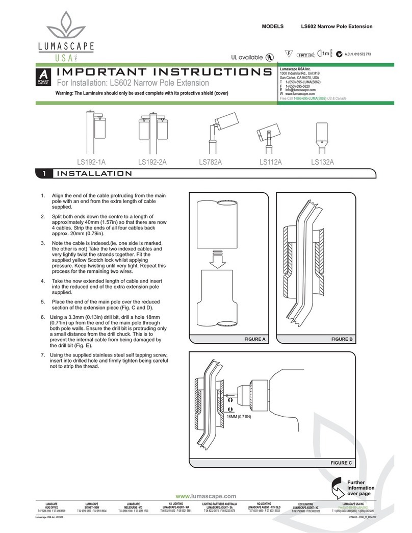
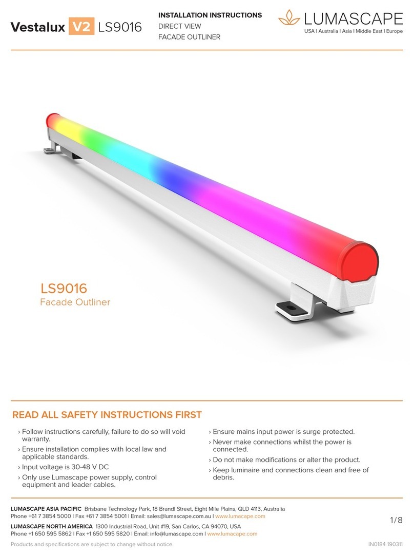
Lumascape LS343-23 25 Series Installation instructions manual

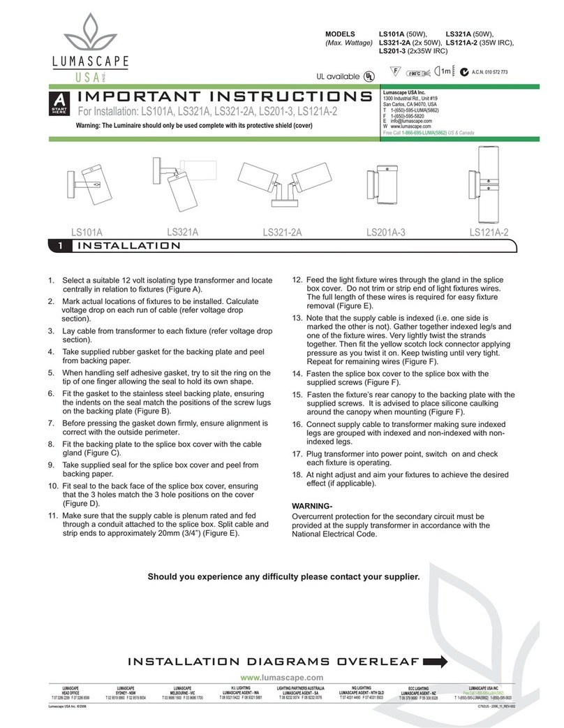
A
START
HERE
Warning: The Luminaire should only be used complete with its protective shield (cover)
IMPORTANT INSTRUCTIONS
For Installation LS343: CFL, PAR, HPS
MODELS LS343-23* * ** ** 25 * *
LS343-24* * ** ** 25 * *
LS343-25* * ** ** 25 * *
LS343-26* * ** ** 25 * *
t90 Ct90 C A.C.N. 010 572 773
6
5
7
3 4
C1084 - 2006_11_REV-002
Lumascape Lighting Industries 2006©
www.lumascape.com.au
LUMASCAPE
HEAD OFFICE
T 07 3286 2299 F 07 3286 6599
LUMASCAPE
SYDNEY - NSW
T 02 9519 6860 F 02 9519 8834
LUMASCAPE
MELBOURNE - VIC
T 03 9686 1900 F 03 9686 1700
ECC LIGHTING
LUMASCAPE AGENT - NZ
T 09 379 9680 F 09 308 9328
H.I. LIGHTING
LUMASCAPE AGENT - WA
T 08 9321 5422 F 08 9321 5881
NQ LIGHTING
LUMASCAPE AGENT - NTH QLD
T 07 4031 4490 F 07 4031 5933
T 1-(650)-595-LUMA(5862) 1-(650)-595-5820
LUMASCAPE USA INC
Free Call 1-866-695-LUMA(5862)
LIGHTING PARTNERS AUSTRALIA
LUMASCAPE AGENT - SA
T 08 8232 0074 F 08 8232 0076
Lumascape Lighting Industries Pty Ltd
38-44 Enterprise Street, Cleveland, QLD 4163, Australia
PO Box 1875, Cleveland D.C., QLD 4163, Australia
T 07 3286 2299
F 07 3286 6599
W www.lumascape.com.au
FOR INDOOR AND OUTDOOR USE
Do not use power tools to tighten screws. Do
not exert downward force on screws while
not fully tightened.
Do not overtighten screws.
CAUTION 21
WARNING
DO NOT SHORTEN, INTERFERE OR DISCONNECT CABLE FROM FITTING. WARRANTY WILL BE VOID IF CABLE ASSEMBLY IS TAMPERED WITH.
Ensure good
drainage soil
Locate Fixtures.
Site fixture, in proximity to cabling, in gravel,
soil or concrete. Use discretion in locating
fixtures as glass can become very hot and
may burn.
Æ240mm (9 / ")
1
2FINISHED
FLOOR LEVEL
DEPTH
DEPENDANT
ON FIXTURE
CONFIG.
250MM (10")
290MM (11 / ")
35
1
2
0MM (13 / ")
3
4
If cable is damaged replace with cable supplied by LUMASCAPE only.
LS343
Fixture
Supply
Conduit
Junction
Box (Direct
burial splice
box)
Finished
Floor Level
Supply Connection
Connect junction box (direct burial splice box) to
supply conduit as per instructions.
For cable only entry connect underwater rated cable
in accordance with local wiring rules.
Alternatively, if ordered with 1/2"NPT conduit adaptor
connect ensuring watertight seal.
North America Only
Warning: Overcurrent protection for secondary
circuit must be provided at the supply transformer in
accordance with the National Electric Code.
FLUSH LID
256MM (10.08")
RECESSED LID
240MM (9.45")
Mount Fixture.
Mount fixture such that the top lip of flange is
flush with finished floor level, as shown
above.
Relamping
Brackets indicate
instalation steps
above
Further
information
over page
90o
Open fixture and Unlock.
Loosen screws with allen key provided. If
necessary gently lever lid out with large
screwdriver. Remove components as shown.
Loosen grub screw.
Insert lamp into fixture.
Check lamp type and wattage with gear tray.
Insert lamp into lampholder (Follow lamp
manufacturers instructions).
Clean any marks from reflector with dry, soft,
lint free cloth. Turn on.
Target Gimbal.
With lamp illuminated insert any
accessory lenses and rotate gimbal
until targeted as required.
Note the finger relief in casting should
point towards target.
Lock Gimbal.
Remove any accessories and whilst
exerting downward pressure on
gimbal, tighten grub screw.
8
10-15 MIN.
60
30
45
Run Fixture.
See Over.
Replace accessories and allow
fixture to burn for 10-15 minutes to
allow any moisture in fixture to
evaporate.
Isolate Fixture Re-lamp (5)
60
60
30
30
45
45
Remove Lid
10-15 MIN.
Run (8) Reseal (9)

GEAR
ASSEMBLY
B
Warning: The Luminaire should only be used complete with its protective shield (cover)
IMPORTANT INSTRUCTIONS
For Installation LS343: CFL, PAR, HPS
MODELS LS343-23* * ** ** 25 * *
LS343-24* * ** ** 25 * *
LS343-25* * ** ** 25 * *
LS343-26* * ** ** 25 * *
t90 Ct90 C A.C.N. 010 572 773
D
C
E
A B
Lumascape Lighting Industries 2006©
www.lumascape.com.au
LUMASCAPE
HEAD OFFICE
T 07 3286 2299 F 07 3286 6599
LUMASCAPE
SYDNEY - NSW
T 02 9519 6860 F 02 9519 8834
LUMASCAPE
MELBOURNE - VIC
T 03 9686 1900 F 03 9686 1700
ECC LIGHTING
LUMASCAPE AGENT - NZ
T 09 379 9680 F 09 308 9328
H.I. LIGHTING
LUMASCAPE AGENT - WA
T 08 9321 5422 F 08 9321 5881
NQ LIGHTING
LUMASCAPE AGENT - NTH QLD
T 07 4031 4490 F 07 4031 5933
T 1-(650)-595-LUMA(5862) 1-(650)-595-5820
LUMASCAPE USA INC
Free Call 1-866-695-LUMA(5862)
LIGHTING PARTNERS AUSTRALIA
LUMASCAPE AGENT - SA
T 08 8232 0074 F 08 8232 0076
Lumascape Lighting Industries Pty Ltd
38-44 Enterprise Street, Cleveland, QLD 4163, Australia
PO Box 1875, Cleveland D.C., QLD 4163, Australia
T 07 3286 2299
F 07 3286 6599
W www.lumascape.com.au
FOR INDOOR AND OUTDOOR USE
9
WARNING
DO NOT SHORTEN, INTERFERE OR DISCONNECT CABLE FROM FITTING. WARRANTY WILL BE VOID IF CABLE ASSEMBLY IS TAMPERED WITH.
If cable is damaged replace with cable supplied by LUMASCAPE only.
90o
F
LAMP SOURCE CONVERSION INSTRUCTION
Seal Fixture.
Ensure seal and sealing surface is clean.
Clean glass if necessary. Incrementally
tighten lid screws using the 3mm Allen key
supplied. Lumascape recommends tightening
in the above Torque Pattern to 2.5 - 3 N.m.
DO NOT OVER TIGHTEN.
NORTH AMERICA only:
As per 2002 NEC Section 305. The SOOW cord must be at least 450mm (18 in.) below a
minimum 2 inch
Isolate and Open Fixture
Ensure the fixture is electrically isolated.
Loosen the screws with the Allen Key
provided. If necessary gently lever lid out with
a large screwdriver.
GIMBAL
LOCKING
SCREW
Remove Gimbal
Remove gimbal by loosening the locking screw
and pulling vertically.
Remove Gear Assembly
Remove gear assembly by
pulling vertically (Note: Gear assembly may be
screwed to fixture body).
GUIDE
PINS
Insert New Gear Assembly
Align holes in gear tray with Threaded Guide
Pins in base of fixture and insert fully, fit S/S nuts
to retain Gear Tray.
Replace/Insert Gimbal and
Lamp
6
Connect and insert gimbal into fixture.
Remove reflector and insert new lamp,
(Check wattage and type with gear label).
Refer installation instruction Over.
Adjust, Aim, Test and Seal
7,8,9
10,11,12
If necessary, readjust and re-aim gimbal
position as per instructions over.
Test and seal fixture as per Instructions
.
7
8
9
1
2
6
5
3
4
Torque Pattern
C1084 - 2006_11_REV-002

www.lumascape.com.au
Lumascape Lighting Industries Pty Ltd
38-44 Enterprise Street, Cleveland, QLD 4163, Australia
Tel (07) 3286 2299 Fax (07) 3286 6599 Email [email protected]
LUMASCAPE
HEAD OFFICE - QLD
Tel (07) 3286 2299
Fax (07) 3286 6599
LUMASCAPE
SYDNEY - NSW
Tel (02) 9519 6860
Fax (02) 9519 8834
LUMASCAPE
MELBOURNE - VIC
Tel (03) 9686 1900
Fax (03) 9686 1700
LUMASCAPE USA INC.
SAN FRANCISCO - CA
Tel 1-(650)-595-5862
Fax 1-(650) 595-5820
H.I. LIGHTING
LUMASCAPE AGENT - WA
Tel (08) 9321 5422
Fax (08) 9321 5881
LIGHTING PARTNERS AUSTRALIA
LUMASCAPE AGENT - SA
Tel (08) 8232 0074
Fax (08) 8232 0076
NQ LIGHTING
LUMASCAPE AGENT - NTH QLD
Tel (07) 4031 4490
Fax (07) 4031 5933
ECC LIGHTING
LUMASCAPE AGENT - NZ
Tel (09) 379 9680
Fax (09) 308 9328
Copyright ©2006 Lumascape Lighting Industries Pty. Ltd. ABN 21 010 572 773www.lumascape.com.au
IMPORTANT INFORMATION
WARNING - To reduce the risk of FIRE or INJURY:
Luminaires and transformers to be installed by qualified installers only.
Luminaires to be used for intended purpose only. e.g Wall Mount fittings must be wall mounted.
Luminaires can become very hot. Use discretion in placement.
Do not touch hot lens, guard, or enclosure.
CAUTION - HOT SURFACE. Keep away from curtains and other combustible material.
Turn Off/Unplug and allow to cool before replacing lamp.
Keep lamp away from materials that may burn.
Never touch lamp with bare fingers. Oil from skin may damage lamp. Hold lamp with soft cloth when installing or replacing.
Do not operate the luminaires with a missing or damaged parts.
Replace any cracked protective shield
Use only lamp type, voltage and wattage as specified by Lumascape on the product label.
Use only genuine Lumascape parts to replace damaged or missing components.
Luminaires supplied with Loctite Silver Grade Anti Seize lubricant on threads. Reapply if needed.
Refer to instructions for installation and operating requirements.
Ensure installation complies with local regulations
SAVE THESE INSTRUCTIONS.
1.
2.
3.
4.
5.
6.
7.
8.
9.
10.
11.
12.
13.
14.
15.
IMPORTANT SAFETY INSTRUCTIONS
C1721 - 2006_11_REV-002
A
232 0074
08) 8232 0076
NQ LIGHTING
LUMASCAPE AGENT - NTH QLD
GHTIN
LUMASCAPE AGENT - NZ
Tel (09) 379 9680
C
ax (09) 308 9328
right ©2006 Lumascape Lighting Industries Pty. Ltd. ABN

Warranty voided if not installed as per installation instructions
INSTALLATION INSTRUCTIONS
Lumascape Lighting Industries Pty Ltd
38-44 Enterprise Street, Cleveland, QLD 4163, Australia
PO Box 1875, Cleveland D.C., QLD 4163, Australia
T 07 3286 2299
F 07 3286 6599
W www.lumascape.com.au
IN0035 - 27 May 2013
FOR INDOOR AND OUTDOOR USELS343: Filter support accessories
t90 C A.C.N. 0105 72 773
90o
1.
4.
2.
5.
3.
6.
lens
secondary
refractor
reflector
LS686 Dichroic Filter
LS685 Linear Spreader lens
Seal fixture.
Ensure seal and sealing surface is clean.
Clean glass if necessary. Tighten lid screws
Using the 3 mm allen key supplied.
Lumascape recommends tightening in the
below torque pattern
Do not overtighten screws, 4 Nm max.
torque order
1
2
6
5
3
4
torque order
1
2
6
5
3
4
DANGER
ISOLATE LUMINAIRE FROM POWER
Failure to isolate power
supply before installation or
maintenance may result in
fire, serious injury, electric
shock, death and may
damage the luminaire.
Power supply must be isolated prior to
connection or disconnection of cables.
Failure to do so will result in damage to
the luminaire components.

Copyright ©2013 Lumascape Lighting Industries Pty. Ltd. ABN 21 010 572 773
www.lumascape.com.au
IN0035 - 27 May 2013
WARNING - To reduce the risk of FIRE or INJURY:
1. Luminaires and transformers to be installed by licensed electrical contractors.
2. Luminaires to be used for intended purpose only.
3. Do not operate the luminaires with a missing or damaged parts.
4. Use only genuine Lumascape parts to replace damaged or missing components.
5. Refer to instructions for installation and operating requirements.
6. Ensure installation complies with local regulations
Voltage insulation test (megger) will permanently damage product and will void warranty.
SAVE THESE INSTRUCTIONS.
SAFETY INSTRUCTIONS
Questions?
Call 07 3286 2299
Email [email protected]
www.lumascape.com.au

Further
information
over page
Instruction Guide
IMPORTANT NOTE:
Human Touch kits are available for LS343 series fixtures in 290mm& 350mm Bodies ONLY!
For Kit Numbers. Follow Instructions Sets
C
LS657, LS658 Instruction Set Followed by Instruction Set
LS654, LS655 Instruction Set Followed by Instruction Set
AC
BC
LS651, LS652 Instruction Set Only
Isolate and remove Gimbal
Check the fixture is electrically isolated.
Unscrew & remove lid. Loosen gimbal
locking screw and remove assembly.
Gimbal
locking screw
Join clip ends
Ensure two hooks on clip are interlocked.
2
Return Gimbal into Fixture
Connect & insert gimbal into fixture. Re-
adjust Rotation, angle & depth. Lock off
Gimbal.
6
Insert Reflector Glass
Insert reflector glass into clip on reflector.
Ensure glass is flat and central against
reflector. Avoid touching Glass as best as
possible.
Instruction Set A REFLECTOR GLASS ATTACHMENT FOR LS657, LSD658 ONLY
3
Attach Clip to Reflector
Positioning the join under the lip of the
reflector. Stretch the clip over the reflector
as shown
5
Gimbal rotation
locking screw
Gimbal height
locking screw
Adjust Gimbal position
Re-aim gimbal to desired focal point. Lock
gimbal depth and rotation.
WARNING
DO NOT SHORTEN, INTERFERE OR DISCONNECT CABLE FROM FITTING. WARRANTY WILL BE VOID IF CABLE ASSEMBLY IS TAMPERED WITH.
A
START
HERE
Warning: The Luminaire should only be used complete with its protective shield (cover)
IMPORTANT INSTRUCTIONS
For Installation LS343 Human Touch Retro-Firt Kits
MODELS LS651, LS652, LS654, LS655,
LS657, LS658
Human Touch Retro-Fit Kits
A.C.N. 010 572 773
Lumascape Lighting Industries 2006©
www.lumascape.com.au
LUMASCAPE
HEAD OFFICE
T 07 3286 2299 F 07 3286 6599
LUMASCAPE
SYDNEY - NSW
T 02 9519 6860 F 02 9519 8834
LUMASCAPE
MELBOURNE - VIC
T 03 9686 1900 F 03 9686 1700
ECC LIGHTING
LUMASCAPE AGENT - NZ
T 09 379 9680 F 09 308 9328
H.I. LIGHTING
LUMASCAPE AGENT - WA
T 08 9321 5422 F 08 9321 5881
NQ LIGHTING
LUMASCAPE AGENT - NTH QLD
T 07 4031 4490 F 07 4031 5933
T 1-(650)-595-LUMA(5862) 1-(650)-595-5820
LUMASCAPE USA INC
Free Call 1-866-695-LUMA(5862)
LIGHTING PARTNERS AUSTRALIA
LUMASCAPE AGENT - SA
T 08 8232 0074 F 08 8232 0076
Lumascape Lighting Industries Pty Ltd
38-44 Enterprise Street, Cleveland, QLD 4163, Australia
PO Box 1875, Cleveland D.C., QLD 4163, Australia
T 07 3286 2299
F 07 3286 6599
W www.lumascape.com.au
CAUTION - This Product Must Only Be Installed/fitted By A Licensed Electrical Worker
C825 - 2006_11_REV-001
1
4

56
B
Warning: The Luminaire should only be used complete with its protective shield (cover)
IMPORTANT INSTRUCTIONS
For Installation LS343 Human Touch Retro-Firt Kits
MODELS LS651, LS652, LS654, LS655,
LS657, LS658
Human Touch Retro-Fit Kits
A.C.N. 010 572 773
Lumascape Lighting Industries 2006©
www.lumascape.com.au
LUMASCAPE
HEAD OFFICE
T 07 3286 2299 F 07 3286 6599
LUMASCAPE
SYDNEY - NSW
T 02 9519 6860 F 02 9519 8834
LUMASCAPE
MELBOURNE - VIC
T 03 9686 1900 F 03 9686 1700
ECC LIGHTING
LUMASCAPE AGENT - NZ
T 09 379 9680 F 09 308 9328
H.I. LIGHTING
LUMASCAPE AGENT - WA
T 08 9321 5422 F 08 9321 5881
NQ LIGHTING
LUMASCAPE AGENT - NTH QLD
T 07 4031 4490 F 07 4031 5933
T 1-(650)-595-LUMA(5862) 1-(650)-595-5820
LUMASCAPE USA INC
Free Call 1-866-695-LUMA(5862)
LIGHTING PARTNERS AUSTRALIA
LUMASCAPE AGENT - SA
T 08 8232 0074 F 08 8232 0076
Lumascape Lighting Industries Pty Ltd
38-44 Enterprise Street, Cleveland, QLD 4163, Australia
PO Box 1875, Cleveland D.C., QLD 4163, Australia
T 07 3286 2299
F 07 3286 6599
W www.lumascape.com.au
C825 - 2006_11_REV-001
4
23
1
23
1
Instruction Set B LAMP GLASS ATTACHMENT FOR LS654 LS655 ONLY
Instruction Set C SEAL GLASS ATTACHMENT FOR ALL LS343 HUMAN TOUCH KITS
Isolate and remove Lid
Check the fixture is electrically isolated.
Unscrew & remove lid.
Remove louvre and hood
Check fixture is cool to touch and remove
the hood and louvre.
Attach new Hood Assembly
Attach the new hood, filter louvre assembly
to gimba.l
Locate Sealed Glass
Gently position the seal evenly into the top
of the fixture.
Push Seal Evenly
Pushing on the seal itself, press the seal
into the fixture with an even pressure.
Gimbal
Seal/Glass
Check position
Ensure the seal is located evenly against
the gimbal.
Instructions 4,5&6Applicable only with kits LS651, LS654 & LS657
Seperate Lid
Remove the lid and screws from the lid
seal.
Replace Glass
Peal seal away from glass. Check that seal
is clean.
Reassemble Lid & Clean
Reassembly Lid into seal, aligning holes.
Insert screws into holes.
Clean both sides of glass and reseal fixture.

www.lumascape.com.au
Lumascape Lighting Industries Pty Ltd
38-44 Enterprise Street, Cleveland, QLD 4163, Australia
Tel (07) 3286 2299 Fax (07) 3286 6599 Email [email protected]
LUMASCAPE
HEAD OFFICE - QLD
Tel (07) 3286 2299
Fax (07) 3286 6599
LUMASCAPE
SYDNEY - NSW
Tel (02) 9519 6860
Fax (02) 9519 8834
LUMASCAPE
MELBOURNE - VIC
Tel (03) 9686 1900
Fax (03) 9686 1700
LUMASCAPE USA INC.
SAN FRANCISCO - CA
Tel 1-(650)-595-5862
Fax 1-(650) 595-5820
H.I. LIGHTING
LUMASCAPE AGENT - WA
Tel (08) 9321 5422
Fax (08) 9321 5881
LIGHTING PARTNERS AUSTRALIA
LUMASCAPE AGENT - SA
Tel (08) 8232 0074
Fax (08) 8232 0076
NQ LIGHTING
LUMASCAPE AGENT - NTH QLD
Tel (07) 4031 4490
Fax (07) 4031 5933
ECC LIGHTING
LUMASCAPE AGENT - NZ
Tel (09) 379 9680
Fax (09) 308 9328
Copyright ©2006 Lumascape Lighting Industries Pty. Ltd. ABN 21 010 572 773www.lumascape.com.au
IMPORTANT INFORMATION
WARNING - To reduce the risk of FIRE or INJURY:
Luminaires and transformers to be installed by qualified installers only.
Luminaires to be used for intended purpose only. e.g Wall Mount fittings must be wall mounted.
Luminaires can become very hot. Use discretion in placement.
Do not touch hot lens, guard, or enclosure.
CAUTION - HOT SURFACE. Keep away from curtains and other combustible material.
Turn Off/Unplug and allow to cool before replacing lamp.
Keep lamp away from materials that may burn.
Never touch lamp with bare fingers. Oil from skin may damage lamp. Hold lamp with soft cloth when installing or replacing.
Do not operate the luminaires with a missing or damaged parts.
Replace any cracked protective shield
Use only lamp type, voltage and wattage as specified by Lumascape on the product label.
Use only genuine Lumascape parts to replace damaged or missing components.
Luminaires supplied with Loctite Silver Grade Anti Seize lubricant on threads. Reapply if needed.
Refer to instructions for installation and operating requirements.
Ensure installation complies with local regulations
SAVE THESE INSTRUCTIONS.
1.
2.
3.
4.
5.
6.
7.
8.
9.
10.
11.
12.
13.
14.
15.
IMPORTANT SAFETY INSTRUCTIONS
C1721 - 2006_11_REV-002
A
232 0074
08) 8232 0076
NQ LIGHTING
LUMASCAPE AGENT - NTH QLD
GHTIN
LUMASCAPE AGENT - NZ
Tel (09) 379 9680
C
ax (09) 308 9328
right ©2006 Lumascape Lighting Industries Pty. Ltd. ABN

Warranty voided if not installed as per installation instructions
INSTALLATION INSTRUCTIONS
Lumascape
Brisbane Technology Park
18 Brandl Street, Eight Mile Plains, QLD 4113, Australia
T +61 7 3854 5000
F+61 7 3854 5001
Wwww.lumascape.com.au
IN0049 170227
Isolate from supply and remove lid
Check the fixture is electrically isolated.
Unscrew & remove lid.
Isolate from supply and remove lid
Check the fixture is electrically isolated.
Unscrew & remove lid.
Screw in filter
Screw filter onto filter ring.
Allen key x1
Screw in filter
Screw filter onto filter ring.
LS343 / LS853: Filters & Louvres
LS692-2 / LS689-2 / 6014-2 / LS6011-2 / LS690-2
LS693 / LS685 / LS691
A.C.N. 0105 72 773
MODELS: Filters & Louvres
INGROUND
Warranty voided if not installed as per installation instructions
WARNING IMPORTANT COMPONENTS
Do not shorten, interfere or
disconnect cable from fitting.
Warranty will be void if cable
assembly is tampered with.
This product must only be installed/
fitted by a licensed electrical worker
HumanTouch™ kits are available for
LS343 series fixtures in 290 mm &
350 mm bodies ONLY!
1.
1. 2. 3.
2. 3. Seal fixture.
Ensure seal and sealing surface is clean.
Clean glass if necessary. Tighten lid screws
Using the 3mm allen key supplied.
Lumascape recommends tightening in the
below torque pattern
Do not overtighten screws, 3 Nm max.
Seal fixture.
Ensure seal and sealing surface is clean.
Clean glass if necessary. Tighten lid screws
Using the 3mm allen key supplied.
Lumascape recommends tightening in the
below torque pattern
Do not overtighten screws, 3 Nm max.
torque order
1
2
6
5
3
4

Copyright ©2017 Lumascape Lighting Industries Pty. Ltd. ABN 21 010 572 773
www.lumascape.com.au
WARNING - To reduce the risk of FIRE or INJURY:
1. Luminaires and transformers to be installed by licensed electrical contractors.
2. Luminaires to be used for intended purpose only.
3. Do not operate the luminaires with a missing or damaged parts.
4. Use only genuine Lumascape parts to replace damaged or missing components.
5. Refer to instructions for installation and operating requirements.
6. Ensure installation complies with local regulations
Voltage insulation test (megger) will permanently damage product and will void warranty.
SAVE THESE INSTRUCTIONS.
SAFETY INSTRUCTIONS
IN0049 170227
Questions?
Call +61 7 3854 5000
Email [email protected]
www.lumascape.com.au

Warranty voided if not installed as per installation instructions
INSTALLATION INSTRUCTIONS
Lumascape Lighting Industries Pty Ltd
38-44 Enterprise Street, Cleveland, QLD 4163, Australia
PO Box 1875, Cleveland D.C., QLD 4163, Australia
T 07 3286 2299
F 07 3286 6599
W www.lumascape.com.au FOR INDOOR AND OUTDOOR USE
LS343: Direct Burial, Aluminium Reectors IP68
t90 C A.C.N. 0105 72 773
90o
rotational lock
tilt adjust
Warranty voided if not installed as per installation instructions
DO NOT
OVERTIGHTEN
NO DOWNWARD
FORCE
NO POWER
TOOLS
WARNING
GIMBAL FEATURES
Fixed or adjustable (fixed not shown)
Finished ground
level
Ensure good
drainage soil
Depth dependant on
Luminaire configuration
290 mm (11.5")
350 mm (13.75")
240 mm
256 mm
flush lid
recessed lid
1. Locate luminaires
Site luminaire, in proximity to cabling, in gravel, soil or concrete.
Use discretion in locating luminaires as glass can become very
hot and may burn.
Type 81 cable entry:
DIRECT BURIAL ARMOURED CABLE
Type 84 cable entry:
MICRO ANTILEACH 3M CABLE ENTRY
2. Supply connection
For type 81 amoured cable entry: Connect
junction box (direct burial splice box) to supply
conduit and cover connections with epoxy
(Epoxy sachet not supplied by Lumascape).
For type 84 cable entry only: Connect cable in
accordance with local wiring rules.
Epoxy sachet not supplied.
To be supplied by contractor
Lumascape recommends 3M
Scotch Cast 2112 epoxy.
finished ground
level
supply
conduit
junction box
(direct burial
splice box)
600 mm
Connect
to 25 mm
diameter
conduit
Strip cable end
and connect as
required according
to local wiring laws
170 mm (minimum
cable bend radius)
50 mm (minimum
cable bend radius)
600 mm
200 mm
(minimum)
Alternate bottom cable entry
690 mm (maximum distance to conduit)
3000 mm length of cable
3090 mm
Flexible armoured cable Flexible cable (requires mechanical protection)
3000 mm
Alternate bottom cable entry
65 mm
(minimum)
DANGER
ISOLATE LUMINAIRE FROM POWER
Failure to isolate power
supply before installation or
maintenance may result in
fire, serious injury, electric
shock, death and may
damage the luminaire.
Power supply must be
isolated prior to connection or
disconnection of cables. Failure to
do so will result in damage to the
luminaire components.
IN0022 - 6 January 2014
finished
ground
level
junction box
(direct burial
splice box)
remote
control
gear
For remote control gear details
refer over
Install remote control gear in a suitable
locatation and connect luminaire. Refer
wiring diagram

Copyright ©2014 Lumascape Lighting Industries Pty. Ltd. ABN 21 010 572 773
www.lumascape.com.au
IN0022 - 6 January 2014
Gimbal height
Fixed
gimbal
Adjustable
gimbal
Gimbal rotation
locking screw
Locking screw
Locking screw
Fixed
gimbal
Adjustable
gimbal
3. 4. 5.
6. 8.
9.
15 min.
Air gap
Isolate and open luminaire
Ensure the luminaire is electrically isolated.
Loosen the screws with the allen key provided.
If necessary gently lever lid out with a large
screwdriver.
Accessories
Add accessories (Note refer to accessory
stacking sheet below). Further gimbal
adjustments may be required with
accessories in place.
Target gimbal
Not applicable to Fixed, Asymmetric
Aluminium Wall Wash Reflectors
(Type XQ / XT / XP)
1. Rotate gimbal until targeted as desired.
2. Adjust gimbal tilt angle by rotating
Tilt Adjust screw with allen key supplied.
7. Lock gimbal
Not applicable to Fixed, Asymmetric
Aluminium Wall Wash Reflectors
(Type XQ / XT / XP)
Lock Gimbal. Whilst exerting downward
pressure on gimbal, tighten rotational lock
grub screw.
Remove lid
Remove lid and any accessories to expose
reflector.
Insert lamp and reflector
Insert lamp into lamp holder.
Power supply must be isolated prior to
connection or disconnection of cables.
Failure to do so will result in damage to
the luminaire components.
Run luminaire
Lay lid partially over luminaire to allow a gap
for any moisture present to evaporate prior to
sealing. Connect to supply and allow to burn
for 10-15 minutes. Seal luminaire.
IMPORTANT - DO NOT ENERGISE
WITHOUT PARTIALLY COVERING LAMP
10.
torque order
1
2
6
5
3
4
torque order
1
2
6
5
3
4
Seal luminaire.
Seal immediately after de-energising.
Ensure seal and sealing surface is clean.
Clean glass if necessary. Tighten lid screws
Using the 3 mm allen key supplied.
Lumascape recommends tightening in the
below torque pattern
Do not overtighten screws, 4 Nm max.

Copyright ©2014 Lumascape Lighting Industries Pty. Ltd. ABN 21 010 572 773
www.lumascape.com.auwww.lumascape.com.au Copyright ©2014 Lumascape Lighting Industries Pty. Ltd. ABN 21 010 572 773
NOTE: The ‘B’ terminal from the remote control gear assembly must be connected to ‘B’ terminal for the ignitor in the luminaire.
The ‘N’ neutral terminal from the remote control gear assembly must be connected to the lamp neutral.
B L N
B B
E
N N
Remote control gear wiring Luminaire
A
E
N
B
N
E
IGNITOR LAMP
Wiring diagram
Gland installation Enclosure orientation
installer to drill holes to
match gland diameter (x2)
Install glands in downward position to ensure water runoff.
NOTE: If orientation of gear enclosure (as shown) is not possible,
then ensure gland entry is also protected by silicone from the inside.
IN0022 - 6 January 2014

Copyright ©2014 Lumascape Lighting Industries Pty. Ltd. ABN 21 010 572 773
www.lumascape.com.au
Relamping instructions
1. Isolate fixture
IN0022 - 6 January 2014
2. Remove lid
Remove lid and any accessories to expose
reflector.
3. Replace lamp
Remove lamp and insert replacement
lamp into lamp holder.
Power supply must be isolated prior to
connection or disconnection of cables.
Failure to do so will result in damage to
the luminaire components.
4. Accessories
Re-insert any accessories (Note refer to
accessory stacking sheet below). Further
gimbal adjustments may be required with
accessories in place.
5.
15 min.
Air gap
Run luminaire
Lay lid partially over luminaire to allow a gap
for any moisture present to evaporate prior to
sealing. Connect to supply and allow to burn
for 10-15 minutes. Seal luminaire.
IMPORTANT - DO NOT ENERGISE
WITHOUT PARTIALLY COVERING LAMP
torque order
1
2
6
5
3
4
torque order
1
2
6
5
3
4
6. Seal luminaire.
Seal immediately after de-energising.
Ensure seal and sealing surface is clean.
Clean glass if necessary. Tighten lid screws
Using the 3 mm allen key supplied.
Lumascape recommends tightening in the
below torque pattern
Do not overtighten screws, 4 Nm max.
DO NOT
OVERTIGHTEN
NO DOWNWARD
FORCE
NO POWER
TOOLS
WARNING

Copyright ©2014 Lumascape Lighting Industries Pty. Ltd. ABN 21 010 572 773
www.lumascape.com.au
Accessories stacking order
Stacking and order of accessories
MH / HIT
Adjustable Aluminium Reflector
XV / XW / XX / XY
2
Other accessory stacking options may be available - consult factory
LS688
Wall wash lens
LS685
Linear spreader lens
XV / XW / XX / XY
Aluminium Reflector
LS649-2
TM
TM
LS636
Brass grill
External accessory
Use with recessed covers only
Not suitable for use in traffic areas
LS6012
Cross hatch louvre
LS686 - R / G / B / Y
Dichroic colour filter
OR OR OR
LS6013
Slatted louvre
Stacking and order of accessories
MH / HIT
Adjustable PureOptics™ Reflector
AV / AW / AX / AY
1
Other accessory stacking options may be available - consult factory
OR OR
LS688
Wall wash lens
LS6012
Cross hatch louvre
LS692-2
TM
LS685
Linear spreader lens
OR OR OR
LS690-2
Prismatic lens
LS6014-2
Cylindrical louvre
LS6011-2
Cross hatch louvre
LS689 -2 R / G / B / Y
Dichroic colour filters
Not compatible with 70 W
AV / AW / AX /AY
PureOptics™
Reflector
LS636
Brass grill
External accessory
Use with recessed covers only
Not suitable for use in traffic areas
LS6013
Slatted louvre
TM
Stacking and order of accessories
MH / HIT
Fixed Aluminium Reflector
XQ / XT / XP
4
XQ / XT / XP
Aluminium Reflector
Other accessory stacking options may be available - consult factory
LS685
Linear spreader lens
LS636
Brass grill
LS688
Wall wash lens
included as standard
External accessory
Use with recessed covers only
Not suitable for use in traffic areas
LS691
Prismatic lens
LS686 - R / G / B / Y
Dichroic colour filter
OR
TM
standard
Stacking and order of accessories
MH PAR30-38, MH CDM-R111
Adjustable R111 & PAR
AJ / AR
3
Other accessory stacking options may be available - consult factory
AJ
R111 Lamp
AR
PAR Lamp
LS636
Brass grill
LS685
Linear spreader lens
LS693
TM
LS6013
Slatted louvre
LS688
Wall wash lens
LS6012
Cross hatch louvre
OR
AND / OR
OR
External accessory
Use with recessed covers only
Not suitable for use in traffic areas
LS691
Prismatic lens
LS686 - R / G / B / Y
Dichroic colour filter
OR
HumanTouch™ Use only with
AR optical system
TM
WARNING - To reduce the risk of FIRE or INJURY:
1. Luminaires and transformers to be installed by licensed electrical contractors.
2. Luminaires to be used for intended purpose only.
3. Do not operate the luminaires with a missing or damaged parts.
4. Use only genuine Lumascape parts to replace damaged or missing components.
5. Refer to instructions for installation and operating requirements.
6. Ensure installation complies with local regulations
Voltage insulation test (megger) will permanently damage product
and will void warranty.
SAVE THESE INSTRUCTIONS.
SAFETY INSTRUCTIONS
IN0022 - 6 January 2014

INSTALLATION INSTRUCTIONS
Lumascape Lighting Industries Pty Ltd
38-44 Enterprise Street, Cleveland, QLD 4163, Australia
PO Box 1875, Cleveland D.C., QLD 4163, Australia
T 07 3286 2299
F 07 3286 6599
W www.lumascape.com.au
IN0047 - 8 Aug 2014
Copyright ©08 Aug 2014 Lumascape Lighting Industries Pty. Ltd. ABN 21 010 572 773
www.lumascape.com.au
Tilt Adjust
Rotational Lock
Tilt Angle
Indicator
Aiming Mark
2.
Finished ground
level
Ensure good
drainage soil
Depth dependant on
Luminaire configuration
290 mm (11.5")
350 mm (13.75")
240 mm
256 mm
flush lid
recessed lid
1.
Site luminaire, in proximity to cabling, in
gravel, soil or concrete. Use discretion
in locating luminaires as glass can become
very hot and may burn.
DIRECT BURIAL ARMOURED CABLE
MICRO ANTILEACH 3M CABLE ENTRY
For type 81 amoured cable entry: Connect junction
box (direct burial splice box) to supply conduit and
cover connections with electrical grade resin as per
instructions.
For type 84 cable entry only: Connect cable in accord-
ance with local wiring rules.
finished ground
level
supply
conduit
junction box
(direct burial
splice box)
600 mm
Connect
to 25 mm
diameter
conduit
Strip cable end
and connect as
required according
to local wiring laws
170 mm (minimum
cable bend radius)
50 mm (minimum
cable bend radius)
600 mm
200 mm
(minimum)
Alternate bottom cable entry
690 mm (maximum distance to conduit)
3000 mm length of cable
3090 mm
Flexible armoured cable Flexible cable (requires mechanical protection)
3000 mm
Alternate bottom cable entry
65 mm
(minimum)
DANGER
ISOLATE LUMINAIRE FROM POWER
Failure to isolate power
supply before installation or
maintenance may result in
fire, serious injury, electric
shock, death and may
damage the luminaire.
DO NOT
OVERTIGHTEN
NO DOWNWARD
FORCE
INGROUND
LS343 Direct Burial
Warranty void if not installed as per installation instructions N653
LS343
Direct Burial
IP68
240 V AC 50 Hz
MH / HIT
NO POWER
TOOLS
KEEP ELECTRONICS FREE
FROM DIRT AND MOISTURE
DO NOT INTERFERE
WITH CABLE ASSEMBLY
Before you begin always check
luminaire label for correct supply
details and lamp type if applicable.
Power supply must be
isolated prior to connection or
disconnection of cables. Failure to
do so will result in damage to the
luminaire components.
When installing a luminaire with
armoured cable and junction box
assembly use electrical grade
resin (contractor to provide) to
water proof electrical connection
in junction box after connection
has been made and tested.

IN0047 - 8 Aug 2014
Copyright ©08 Aug 2014 Lumascape Lighting Industries Pty. Ltd. ABN 21 010 572 773
www.lumascape.com.au
3. 4. 5.
Type 81 connection only
Connect according to junction box installation
instructions and local wiring rules.
Connect wiring and test prior to potting. Add
electrical grade epoxy resin to water proof
junction box.
Using a screwdriver seal junction box.
Ensure not to over tighten.
NOTE: If ordered without
junction box assembly,
connect in accordance with
local wiring rules. Power supply must be isolated prior to connection
or disconnection of cables. Failure to do so will
result in damage to the luminaire components.
6.
Make sure the fixture is electrically isolated
before connecting the luminaire cable to the
power supply.
7.
Remove any protective stickers that may be
there covering screw holes for the lid on the
luminaire body.
Power supply must be isolated prior
to connection or disconnection of
cables. Failure to do so will result in
damage to the luminaire components.
4.
Remove lid and any accessories to expose
reflector.
5.
Unscrew and remove reflector
from luminaire.
6.
Insert lamp into lamp holder and replace
reflector.
7.
1. Rotate gimbal until is
targeted as desired.
2. Adjust gimbal tilt angle by rotating
screw with allen key supplied.
Approximate angle can
be read from the
Tilt Angle Indicator.
20° 20°
40°

IN0047 - 8 Aug 2014
Copyright ©08 Aug 2014 Lumascape Lighting Industries Pty. Ltd. ABN 21 010 572 773
www.lumascape.com.au
8. 9. 10.
15 min.
Air gap
Add accessories (Note instructions for
accessories stacking order below). Further
gimbal adjustments may be required with
accessories in place.
Lay lid partially over luminaire to allow a gap for
any moisture present to evaporate prior to
sealing. Connect to supply and allow to burn for
10-15 minutes. Seal luminaire immediately after
de-energising.
IMPORTANT - DO NOT ENERGISE WITHOUT
PARTIALLY COVERING LAMP
Lock Gimbal. Whilst exerting downward
pressure on gimbal, tighten rotational lock
grub screw.
11.
torque order
1
2
6
5
3
4
torque order
1
2
6
5
3
4
Ensure seal and sealing surface is clean.
Clean glass if necessary. Replace and
tighten lid screws using the 3 mm allen
key (supplied). Lumascape recommends
tightening in the torque pattern below:
DO NOT OVER TIGHTEN
Accessories stacking order
1
Other accessory stacking options may be available - consult factory
OR OR
Wall wash lens
Cross hatch louvre
TM
Linear spreader lens
OR OR OR
Prismatic lens
Cylindrical louvre
Cross hatch louvre
Dichroic colour filters
Not compatible with 70 W
Reflector
Brass grill
External accessory
Use with recessed covers only
Not suitable for use in traffic areas
Slatted louvre
TM

IN0047 - 8 Aug 2014
Copyright ©08 Aug 2014 Lumascape Lighting Industries Pty. Ltd. ABN 21 010 572 773
www.lumascape.com.au
WARNING - To reduce the risk of FIRE or INJURY:
1. Luminaires and transformers to be installed by licensed electrical contractors.
2. Luminaires to be used for intended purpose only.
3. Do not operate the luminaires with a missing or damaged parts.
4. Use only genuine Lumascape parts to replace damaged or missing components.
5. Refer to instructions for installation and operating requirements.
6. Ensure installation complies with local regulations
Voltage insulation test (megger) will permanently damage product and will void warranty.
SAVE THESE INSTRUCTIONS.
SAFETY INSTRUCTIONS
Questions?
Call +61 7 3286 2299
Email [email protected]
www.lumascape.com.au

Warranty void if not installed as per installation instructions
INSTALLATION INSTRUCTIONS
Lumascape Lighting Industries Pty Ltd
38-44 Enterprise Street, Cleveland, QLD 4163, Australia
PO Box 1875, Cleveland D.C., QLD 4163, Australia
T 07 3286 2299
F 07 3286 6599
W www.lumascape.com.au
IN0067 - 6 May 2014
Copyright ©2014 Lumascape Lighting Industries Pty. Ltd. ABN 21 010 572 773
www.lumascape.com.au
FOR INDOOR AND OUTDOOR USEMounting Collar: LS640-2, LS644-2, LS647-2
2. 3.
DANGER
ISOLATE LUMINAIRE FROM POWER
Failure to isolate power
supply before installation or
maintenance may result in
fire, serious injury, electric
shock, death and may
damage the luminaire.
1.
Use dimensions above for diameter and
profile the different mounting collars.
Mount collar securely in desired floor media.
If installation of fixture into mounting collar is
to be delayed we recommend the installation
of a cover plate. These are available from
Lumascape, please consult your dealer.
LS640-2 / LS644-2 / LS647-2
mounting collar
Adjust screws to securely
fasten mounting collar in
desired floor media.
Flanges can be turned to
allow for securing in very
thick media.
6 mm
15 mm
5 mm
6 mm
13 mm
8 mm
Ø
210 mm
Ø
201 mm
42 mm
41 mm
220 mm
LS640-2 LS644-2 LS647-2
Ø
179 mm
Ø
164 mm
29 mm
41 mm
123 mm
6 mm
15 mm
8 mm
Ø
264 mm
290 mm
350 mm
Ø
249 mm
34 mm
37 mm
180 mm
DO NOT
OVERTIGHTEN
NO DOWNWARD
FORCE
NO POWER
TOOLS
This manual suits for next models
3
Table of contents
Other Lumascape Outdoor Light manuals
Popular Outdoor Light manuals by other brands

urban ambiance
urban ambiance UQL1092 installation instructions

Ingo Maurer
Ingo Maurer Oskar instructions

Classy Caps
Classy Caps SSL810 Lighting instructions

ARCHIPELAGO LIGHTING
ARCHIPELAGO LIGHTING LED SL-9 installation instructions

Gainsborough
Gainsborough K845 manual

Facom
Facom 779.CL5 instruction manual