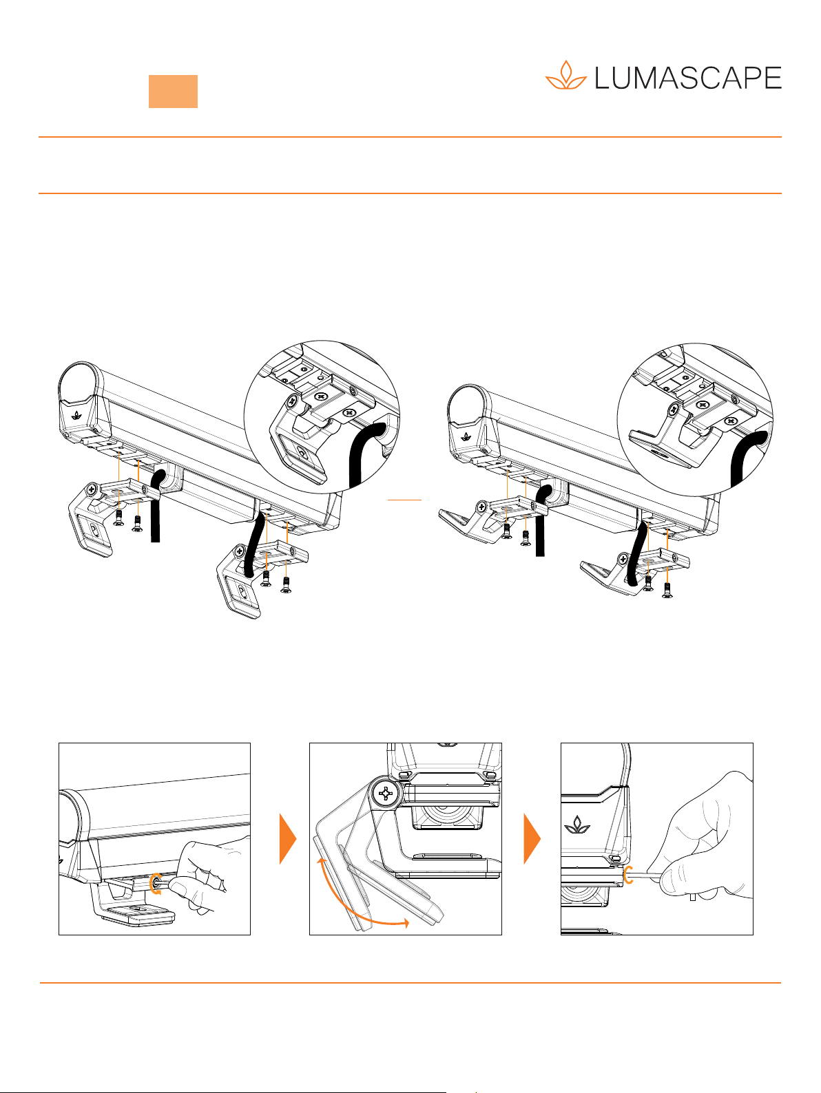
INSTALLATION INSTRUCTIONS
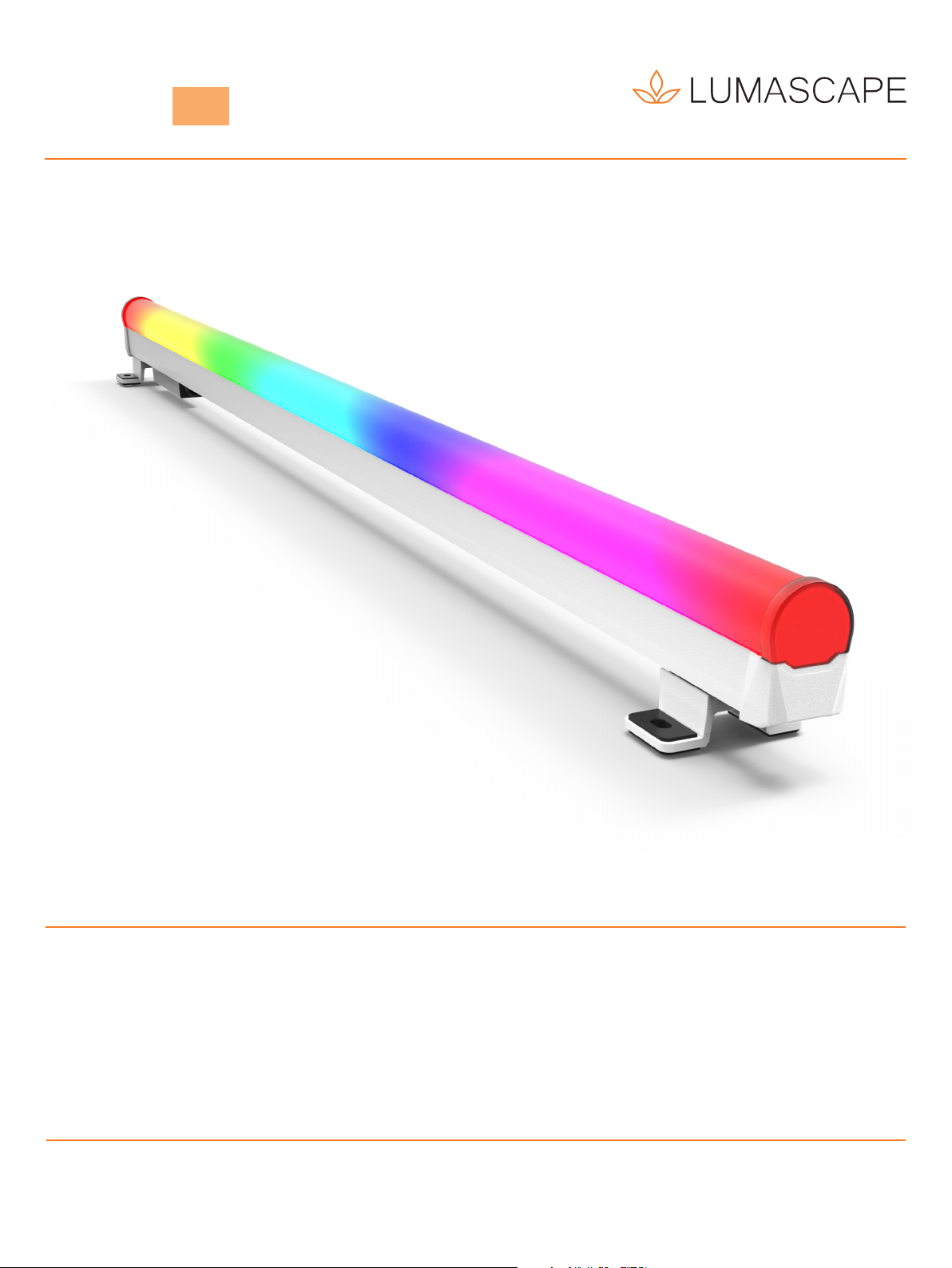
DIRECT VIEW
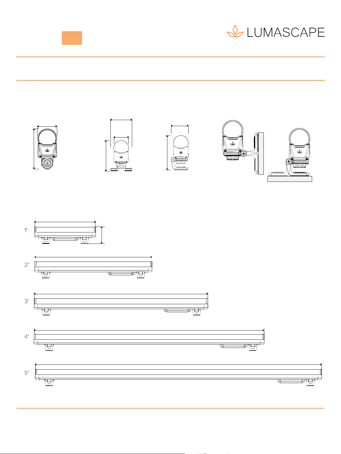
FACADE OUTLINER
LUMASCAPE ASIA PACIFIC Brisbane Technology Park, 18 Brandl Street, Eight Mile Plains, QLD 4113, Australia
Phone
+61
7
3854
5000
|
Fax
+61
7
3854
5001
|
Email:
[email protected] |
www.lumacape.comLUMASCAPE NORTH AMERICA 1300 Industrial Road, Unit #19, San Carlos, CA 94070, USA
Phone
+1
650
595
5862
|
Fax
+1
650
595
5820
|
Email:
[email protected] |
www.lumacape.comProducts and specifications are subject to change without notice.
USA I Australia I Asia I Middle East I Europe
8 / 8
IN0184 190311
Vestalux V2 LS9016
Maximum Circuit Loading - Single Run
LED Power Max Leader Cable Length from
LS6550 to first fitting
Feet of Linear fixture per / 48V Power Supply
120W 240W 320W 480W 600W
4W/ft
15m / 50ft 20 44 56 80 96
30m / 98ft 20 44 56 76 88
50m / 164ft 20 40 52 64 72
6W/ft
15m / 50ft 14 28 36 56 64
30m / 98ft 14 28 36 48 56
50m / 164ft 14 26 34 44 48
Luminaire Luminaire Luminaire Luminaire
T
Network Topology - PowerSync™ Low Voltage
Control Signal
120-277V
50/60Hz
Power Supply
(PSU)
LS6550 LV
PowerSync™
Data Injector
easyglow
tm
humantouchtm opticlear
tm p wersync
tm
gripglass
tm electropolish+
tm
microantileachtm cooldrivetm
pure pticstm
I
Leader Cable
PowerSync™ Topology 1 - Single Trunk Cable
Circuit Calculation Example
4W/ft 50m / 164ft 20
20ft of linear fixture = 5 x 4ft luminaires
NOTE: The above diagrams are intended to show electrical pathways between luminaires and ancillary device. These diagrams are not intended to show type
or colour of cord / wire, luminaire input voltage rating, wire gauge or approved use of the cord / wire supplied with luminaires.
Terminator
Use PowerSync™ terminator, supplied with
leader cable to terminate last luminaire
in chain.
T
Maximum Current
Through Cables & Connectors ≤10.4A.
I
Control Resolution
DMX Channel Allocation
RGBA / RGBW Single Colour
Pixel Size 1ft 2ft 3ft 4ft 5ft 1ft 2ft 3ft 4ft 5ft
Full Fixture 4 4 4 4 41 1 1 1 1
300mm / 12.0" 4 8 12 16 20 1 2 3 4 5
150mm / 6.0" 8 16 24 32 40 2 4 6 8 10
75mm / 3.0" 16 32 48 64 80 4 8 12 16 20
19mm / 0.75" 64 128 192 256 320 16 32 48 64 80
For assistance, contact Lumascape. Always observe electrical codes.
Up to 24 luminaires per 48V PowerSync circuit / LS6550
Values in the above table show the maximum circuit loading per 48V circuit.
Values are based on end to end spacing (ETE). Extended fixture cables, inclusion of jumper cables, or longer leader cable will eect loading. Contact factory
for details.
Circuits can be made up of up to 24 fixtures in any length, up to the maximum circuit loading in the table above.
Circuits are limited to maximum 12.8A.
For non-continuous runs, contact factory for details.
To calculate the maximum number of interconnected luminaires per run / circuit, see example below.
Leader Cable
20ft
4ft 4ft 4ft4ft 4ft
Extra channels required when enabling optional Advanced Control Modes.
• Variable Dimming Smoothness Mode - requires 1 extra channel per luminaire
• Variable Dimming Smoothness + Strobe Mode - requires 3 extra channels per luminaire