LumenRadio Mira MWA-N2 User manual

User guide / operational instruction
Mira MWA-N2 (TimoTwo)
PA4 (2019-08-15)
SUMMARY
This document describes the technical and user aspects of the Mira MWA-N2 / TimoTwo radio module.

- 2 -
1!Introduction ........................................................................................................................................... 3!
1.1!What is CRMX™ ................................................................................................................................................Error! Bookmark not defined.!
1.2!CRMX TimoTwo ................................................................................................................................................Error! Bookmark not defined.!
1.3!Features ............................................................................................................................................................................................................ 3!
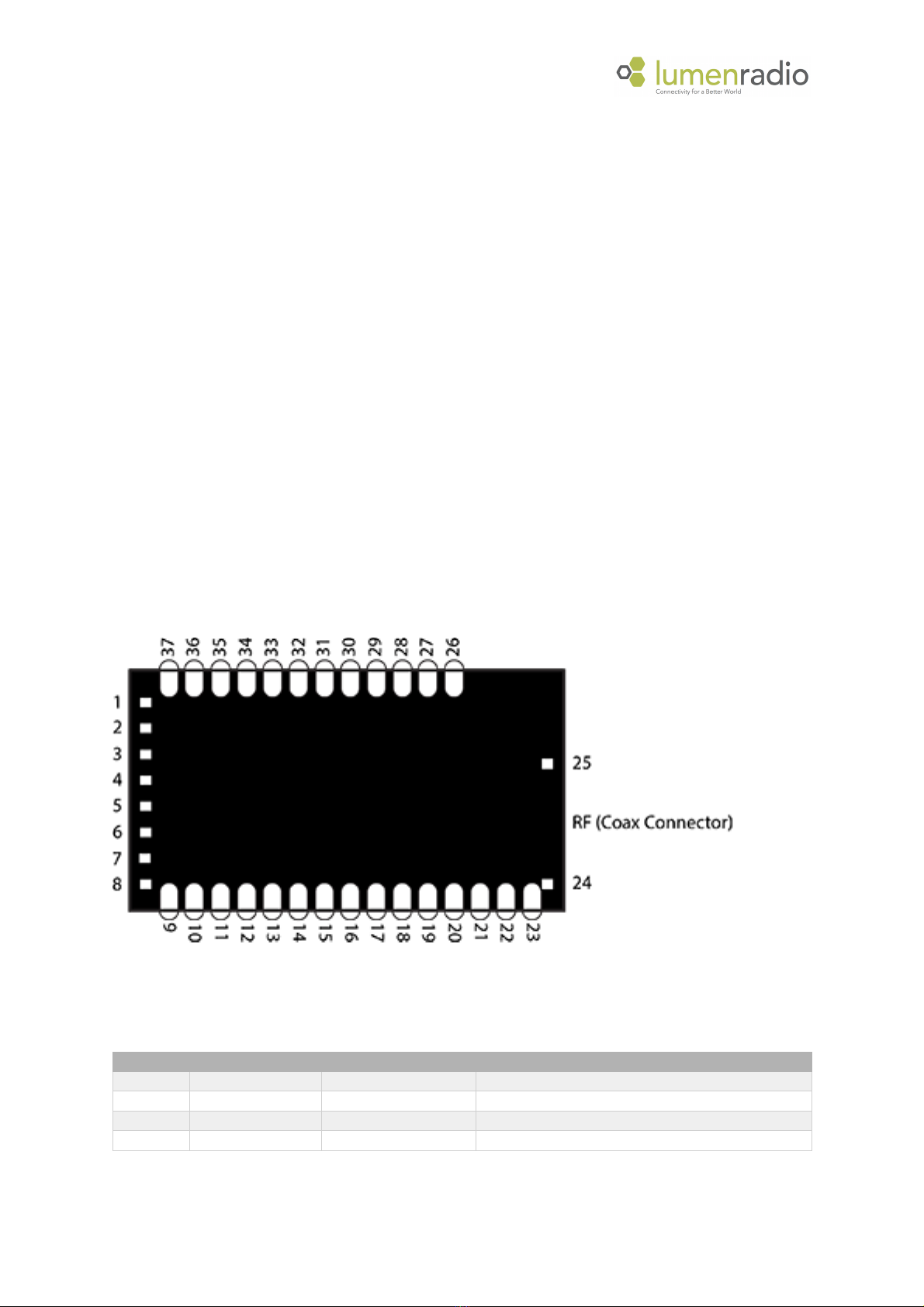
2!Pin assignment and functions ................................................................................................................. 3!
2.1!Pin assignments................................................................................................................................................................................................ 3!
2.2!Pin functions ..................................................................................................................................................................................................... 3!
2.3!Typical Application Circuit ............................................................................................................................................................................... 5!
3!Referene design and PCB mounting ....................................................................................................... 5!
3.1!Reference design files ...................................................................................................................................................................................... 5!
3.2!PCB mounting ................................................................................................................................................................................................... 5!
3.2.1!Antenna ................................................................................................................................................................................................ 5!
3.2.2!Layout considerations for the main board ......................................................................................................................................... 5!
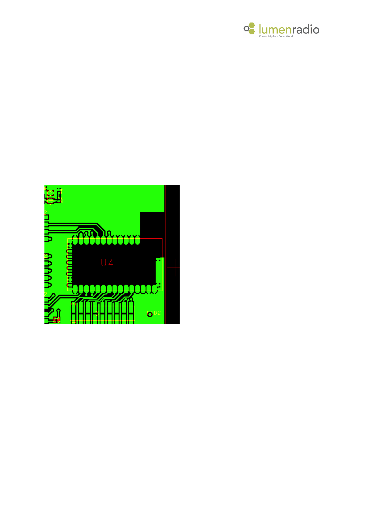
3.2.3!Layout Example.................................................................................................................................................................................... 6!
4!Specifications ......................................................................................................................................... 7!
4.1!Electrical ........................................................................................................................................................................................................... 7!
5!Compliance information ......................................................................................................................... 7!
5.1!FCC information ............................................................................................................................................................................................... 7!
5.1.1!Federal Communication Commission Interference Statement ......................................................................................................... 7!
5.1.2!FCC Declaration of Conformity ........................................................................................................................................................... 8!
5.1.3!FCC Radiation Exposure Statement .................................................................................................................................................... 8!
5.1.4!End Product Labeling ........................................................................................................................................................................... 8!
5.1.5!Manual Information to the End User ................................................................................................................................................. 8!
5.2!Industry Canada statement ............................................................................................................................................................................. 9!
5.3!CE....................................................................................................................................................................................................................... 9!
5.4!Compliance Marking ........................................................................................................................................................................................ 9!
5.4.1!FCC & Industry Canada ........................................................................................................................................................................ 9!
5.4.2!Other Compliances ............................................................................................................................................................................ 10!
6!History ................................................................................................................................................. 10!

- 3 -
1 Introduction
1.1 Features
- Supports ANSI E1.11 - DMX512-A and ANSI E1.20 - RDM
- Connectivity based on Bluetooth Smart, allowing for easy connection from any phone or tablet
- Cognitive coexistence - dynamically avoids occupied frequencies
- DMX fidelity and frame integrity
- DMX frame rate and frame size auto sensing
- Fixed 5 ms end-to-end latency
- Small footprint at 18.5 mm x 33.5 mm
- U.FL/IPEX external antenna connector
- All configuration data is stored in non-volatile memory, 20 years data retention
- Over-the-air firmware upgrades
2 Pin assignment and functions
This section describes the pin assignments and pin functions.
2.1 Pin assignments
Module seen from the top
2.2 Pin functions
Pin
Name
Pin type
Description
1
VSS
Power
Ground
2
IRQ
Digital output
Interrupt signal, active low
3
CS
Digital Input
Chip select, active low
4
SCK
Digital input
SPI clock

- 4 -
5
MOSI
Digital input
SPI Master out, slave in
6
MISO
Digital output
SPI Master in, slave out
7
VSS
Power
Ground
8
DMX_TX
Digital output
DMX TXD
9
VSS
Power
Ground
10
RS485_DE
Digital output
RS485 control signal
11
RS485_RE
Digital output
RS485 control signal
12
DMX_RXD
Digital input
DMX RXD (3.3V max)
13
RDI_LVL0
Digital output
LED control
14
RDI_LVL1
Digital output
LED control
15
RDI_LVL2
Digital output
LED control
16
RDI_LVL3
Digital output
LED control
17
RDI_LVL4
Digital output
LED control
18
RDM
Digital output
LED control
19
DMX
Digital output
LED control
20
N.C.
No connection
Do not connect
21
N.C.
No connection
Do not connect
22
VSS
Power
Ground
23
VSS
Power
Ground
24
VSS
Power
Ground
25
VSS
Power
Ground
26
VSS
Power
Ground
27
VSS
Power
Ground
28
SCL
Digital input/output
I2C clock to RGB LED driver1
29
SDA
Digital input/output
I2C clock to RGB LED driver1
30
VSS
Power
Ground
31
N.C.
No connection
Do not connect
32
LINK_SW
Digital input
Link control switch input
33
STATUS_LED
Digital output
LED control
34
LINKED
Digital output
LED control
35
RF_LINK
Digital output
LED control
36
VDD
Power
3.3VDC
37
VSS
Power
Ground
ANT
RF ANT
RF
Antenna connector
1Shall be pulled high (to Vcc) through a 4.7 kOhm resister if RGB LED is used.

- 5 -
2.3 Typical Application Circuit
3 Reference design and PCB mounting
3.1 Reference design files
A complete reference design including PCB layout and PCB design guidelines is available from LumenRadio to
make integration easier. Please send your inquiry to LumenRadio for details.
3.2 PCB mounting
3.2.1 Antenna
The antenna connector of the module is of u.FL type. A coax cable with a characteristic impedance of 50 ohm
shall be used to connect an antenna.
The antenna shall have a characteristic impedance of 50 ohm at 2.45GHz.
3.2.2 Layout considerations for the main board
TimoTwo has been specifically designed in order to achieve good RF performance. In order to maintain this,
there are some guidelines that we would like to stress:
The use of ground planes also on the main board cannot be emphasized enough. Good decoupling of any high
speed digital circuitry is a must. Many embedded type microprocessors today have clock frequencies with
clocks or overtones that reach well into the GHz range. It is perfectly possible for an embedded design to pass
any EMC certification and still cause disturbances that will block the RF reception of the TimoTwo module. The
sensitivity of the TimoTwo receiver is -96dBm therefore it is recommended to keep disturbances below -
100dBm in the frequency range of operation.

- 6 -
A near field probe connected to a spectrum analyzer will show if there are any disturbances present on the
2.45 GHz band generated by the microprocessor or any other device that is placed on the main board. Pay
special attention to readymade LAN-products "Server in a RJ connector". They pass EMC certifications, but
some of them radiate badly on 2.45 GHz. If disturbances can be seen on a spectrum analyzer - then the
TimoTwo module will have impaired reception.
TimoTwo has a supply voltage decoupling on the circuit board. The supply voltage still needs to be adequately
filtered. If any disturbance or intermittent communication failures occur, as one of the trouble shooting steps -
check the supply voltage for drop-outs, switch supply ripple etc.
3.2.3 Layout Example
1. The TOP layer inside the footprint must be free from copper. There is a ground plane on the module, but
there are also supply lines. It is an unnecessary risk to rely on solder mask lacquer for isolation.
2. An area around the board edge must be kept clear from copper on all layers as depicted in the picture
below.
Minimum dimensions for ground plane clearance for optimum performance are shown below:

- 7 -
4 Specifications
4.1 Electrical
Symbol
Parameter
Min
Typ
Max
Unit
VDD
Supply voltage
3.0
3.3
3.6
V
IDD
Supply current
150
250
mA
TA
Operating temperature
-20
75
°C
VIL
Input voltage logic low
0
0.9
V
VIH
Input voltage logic high
2.5
3.3
V
ILED
Max current on LED pins
5
mA
frange
Operating frequency range
2402
2480
MHz
RXsens
Receiver sensitivity
-96
dBm
TXpout
TX output power1
5
20
dBm
1From 2dBi antenna
5 Compliance information
5.1 FCC information
5.1.1 Federal Communication Commission Interference Statement
This equipment has been tested and found to comply with the limits for a Class B digital device, pursuant to
Part 15 of the FCC Rules. These limits are designed to provide reasonable protection against harmful
interference in a residential installation. This equipment generates, uses and can radiate radio frequency
energy and, if not installed and used in accordance with the instructions, may cause harmful interference to
radio communications. However, there is no guarantee that interference will not occur in a particular

- 8 -
installation. If this equipment does cause harmful interference to radio or television reception, which can be
determined by turning the equipment off and on, the user is encouraged to try to correct the interference by
one of the following measures:
• Reorient or relocate the receiving antenna.
• Increase the separation between the equipment and receiver.
• Connect the equipment into an outlet on a circuit different from that to which the receiver is
• connected.
• Consult the dealer or an experienced radio/TV technician for help.
FCC Caution
Any changes or modifications not expressly approved by the party responsible for compliance could void the
user's authority to operate this equipment. This device complies with Part 15 of the FCC Rules. Operation is
subject to the following two conditions:
(1) This device may not cause harmful interference, and
(2) This device must accept any interference received, including interference that may cause undesired
operation.
5.1.2 FCC Declaration of Conformity
We LumenRadio AB, Svangatan 2B, 41668 Gothenburg, Sweden, declare under our sole responsibility that
Mira MWA-N2 comply with Part 15 of FCC Rules.
5.1.3 FCC Radiation Exposure Statement
This equipment complies with FCC radiation exposure limits set forth for an uncontrolled environment. This
equipment should be installed and operated with minimum distance 20cm between the radiator & your body.
This transmitter must not be co-located or operating in conjunction with any other antenna or transmitter.
This device is intended only for OEM integrators under the following conditions:
(1) The antenna must be installed such that 20 cm is maintained between the antenna and users, and
(2) The transmitter module may not be co-located with any other transmitter or antenna,
IMPORTANT NOTE:
In the event that these conditions cannot be met (for example certain laptop configurations or co-location
with another transmitter), then the FCC authorization is no longer considered valid and the FCC ID cannot be
used on the final product. In these circumstances, the OEM integrator will be responsible for re-evaluating the
end product (including the transmitter) and obtaining a separate FCC authorization.
5.1.4 End Product Labeling
This transmitter module is authorized only for use in device where the antenna may be installed such that 20
cm may be maintained between the antenna and users.The final end product must be labelled in a visible
area with the following:“Contains FCC ID: XRSTIMOMWAN201”.
5.1.5 Manual Information to the End User
The OEM integrator has to be aware not to provide information to the end user regarding how to install or
remove this RF module in the user’s manual of the end product which integrates this module.

- 9 -
5.2 Industry Canada statement
This device complies with Industry Canada licence-exempt RSS standard(s). Operation is subject to the
following two conditions: (1) this device may not cause interference, and (2) this device must accept any
interference, including interference that may cause undesired operation of the device.
Le présent appareil est conforme aux CNR d'Industrie Canada applicables aux appareils radio exempts de
licence. L'exploitation est autorisée aux deux conditions suivantes : (1) l'appareil ne doit pas produire de
brouillage, et (2) l'utilisateur de l'appareil doit accepter tout brouillage radioélectrique subi, même si le
brouillage est susceptible d'en compromettre le fonctionnement.
Caution Exposure:
This device meets the exemption from the routine evaluation limits in section 2.5 of RSS102 and users can
obtain Canadian information on RF exposure and compliance.
Le dispositif répond à l'exemption des limites d'évaluation de routine dans la section 2.5 de RSS102
et les utilisateurs peuvent obtenir des renseignements canadiens sur l'exposition aux RF et le respect.
This equipment should be installed and operated with a minimum distance of 20 centimeters between the
radiator and your body.
Cet équipement doit être installé et utilisé avec une distance minimale de 20 centimètres entre le radiateur et
votre corps.
The final end product must be labeled in a visible area with the following:
The Industry Canada certification label of a module shall be clearly visible at all times when installed in the
host device, otherwise the host device must be labelled to display the Industry Canada certification number of
the module, preceded by the words “Contains transmitter module”, or the word “Contains”, or similar wording
expressing the same meaning, as follows:
Contains transmitter module IC: 8879A-TIMOMWAN201
where 8879A-TIMOMWAN201 is the module’s certification number.
5.3 CE
Mira MWA-N2 and TimoTwo comply with the Essential Requirements of RED (Radio Equipment Directive) of
the European Union (2014/53/EU). Mira MWA-N2 and TimoTwo meet the ETSI EN 300 328 V2.1.1
conformance standards for radio performance.
5.4 Compliance Marking
5.4.1 FCC & Industry Canada
CRMX modules are FCC certified radio module that carries a “Modular” grant CRMX radio modules complies to
the “Intentional Radiator” portion (Part 15c) for FCC certification: Part 15.247 Transmitter tests.
An end product, incorporating a CRMX module, does not require additional testing or authorization for the
CRMX transmitter (or transceiver, in the case of RDM or Flex products). Host end products can use the FCC ID
of the certified module as the FCC ID of the host end product. A label displaying the CRMX module’s FCC ID
must be affixed and visible on the host end product for approval
FCC IDs are required for host end products with radio transmitters.

- 10 -
5.4.2 Other Compliances
For other local compliance regulations (CE, UL, CSA, SRRC, C-Tick, etc.) you are responsible as the product
manufacturer to ensure all required compliance testing is completed. LumenRadio are happy to advise on
compliance testing – please contact help@lumenradio.com for details.
6 History
Revision
Description
Date
PA1
Original version
2019-06-03
PA2
Updated FCC and. IC statements
2019-07-03
PA3
Corrected typo in FCC and IC IDs
2019-08-13
PA4
Corrected format of OC ID.
2019-08-15
Table of contents
Other LumenRadio Control Unit manuals
Popular Control Unit manuals by other brands

Futek
Futek LSB200 manual

Grundfos
Grundfos MP 204 Installation and operating instructions

Busch-Jaeger
Busch-Jaeger Coldewey Media box quick start guide

Bürkert
Bürkert 0460 operating instructions

Freescale Semiconductor
Freescale Semiconductor TWR-LCD user manual

Graco
Graco PM5 238513 Instructions-parts list

iNels
iNels eLAN-RF-Wi-003 installation manual

Unitronics
Unitronics MJ20-MEM1 Installation Guide & Technical Specifications

Carel
Carel UltraCella Commissioning manual

Gates
Gates MOBILE CRIMP 4-20 Safety and operating manual

EasyIO
EasyIO EasyIOeu SH-SystemView7 Configuration manual

MITS
MITS 88-RMB2 user manual