TEST BEFORE
INSTALLING
Our production, packaging and shipping process is accompanied by a rigorous quality control procedure.
All Light Sheets are subjected to a burn in period and are tested before packaging to ensure
operation
of
the
highest
quality.
Due
to
possible
unforeseen
issues
with
shipping
and
handling,
we
advise that all Light Sheets be inspected at time of delivery and dry-t tested for proper illumination
prior to mounting and again before the forward facing material is installed.
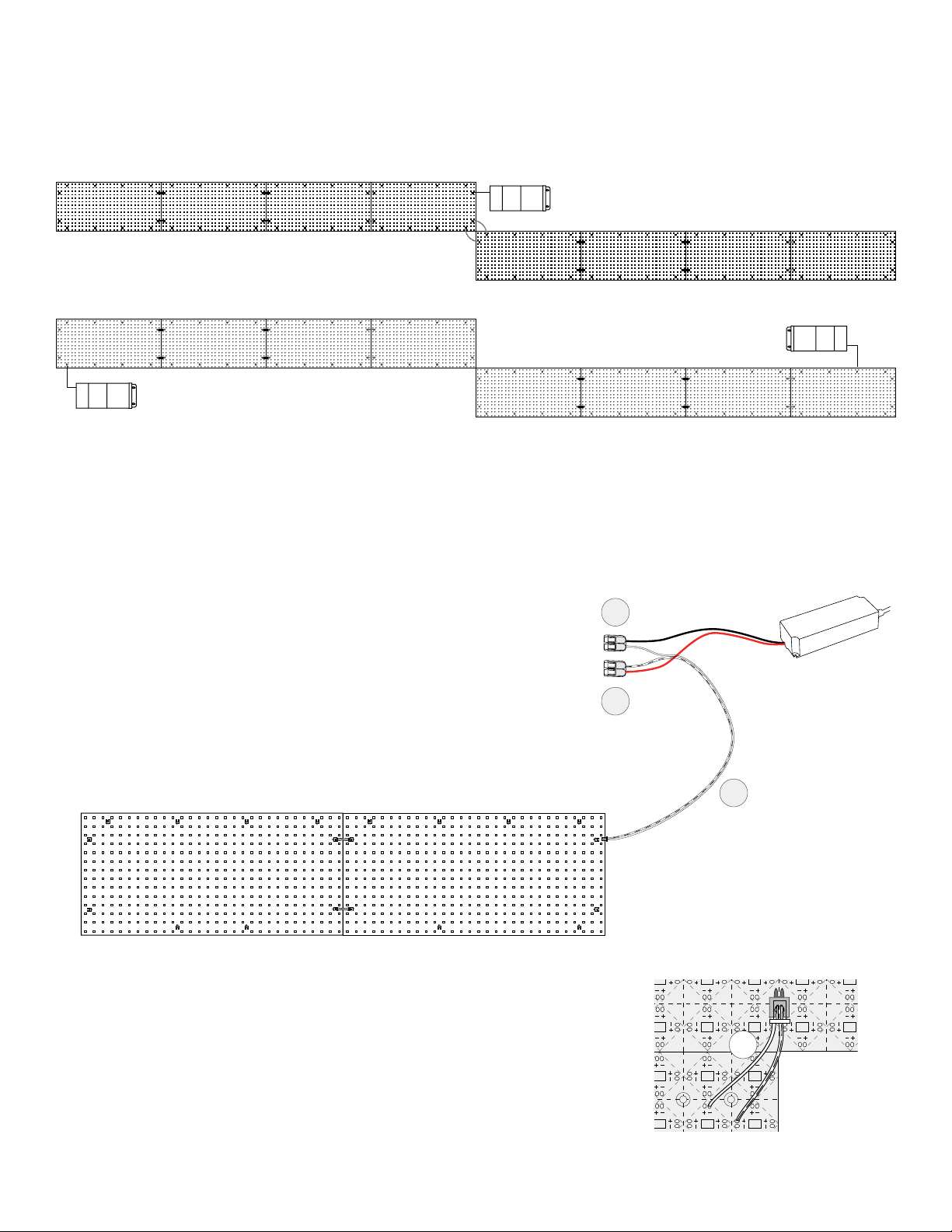
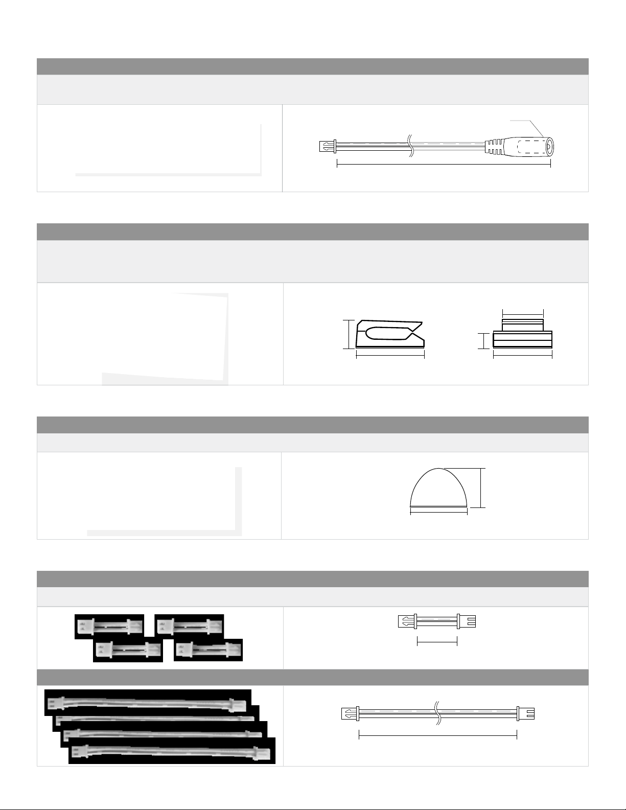
FRAGILE 2-PIN
CONNECTION
BLOCKS
DISCONNECT POWER AT THE SOURCE BEFORE REMOVING ANY 2-PIN CONNECTION BLOCKS.
The
integrated 2-pin connection blocks are made of plastic which can be damaged if made to bear weight.
Use domed spacing bumpers (included) to bear the weight of any forward facing material in horizontal
applications and to act as a safeguard to protect the Light Sheet in vertical applications.
DRILLING
DISCONNECT POWER AT THE SOURCE BEFORE ALTERING THE SHEET IN ANY WAY. Light Sheets
have specic areas where holes can be made in the sheet. The smaller diameter circles on the Light
Sheet (0.12” / 3mm) indicate the maximum diameter of screw or other fastener’s shaft that can be used
without causing damage to the Light Sheet’s power distribution grid. The larger diameter circle (0.24” /
6mm) is the maximum diameter of the screw head that can be used to without causing damage.
INSTALLATION
TEMPERATURE
Due to the characteristics of the 3M adhesive backing, installation environments and locations should
be taken into consideration. Low temperatures can cause longer cure times for permanent adhesion.
STORAGE
STORAGE Store
Light Sheets
in a clean, dry area on a at, horizontal surface. Do not open the anti-static
envelope
until ready to install. Ideal storage conditions: Temperature of 68° – 77°F, 50% humidity.
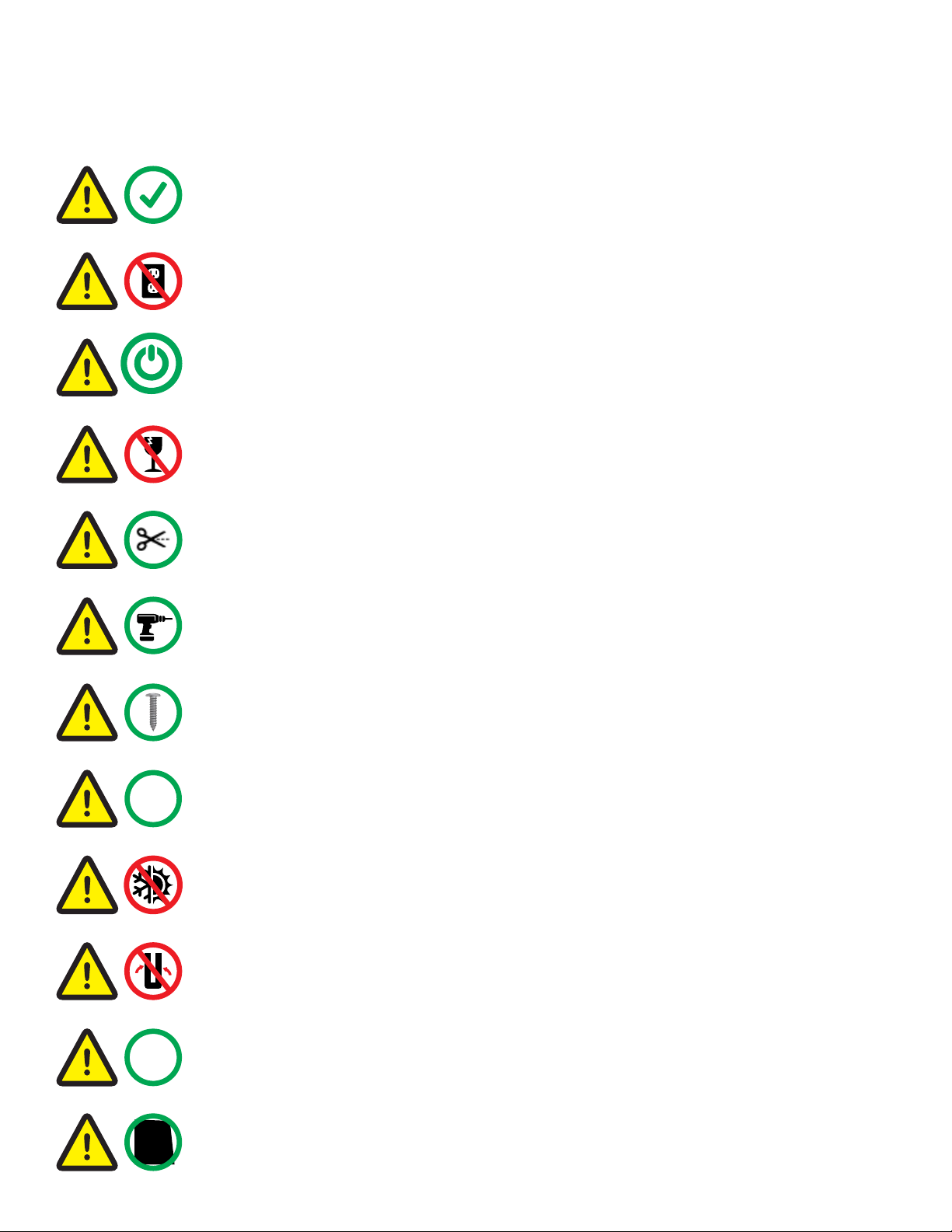
DO NOT
CONNECT TO AC
POWER
ANY DIRECT CONNECTION OF LIGHT SHEETS TO AC CURRENT WILL DAMAGE THE LEDs.
Be sure to use a UL Listed or UL Recognized Class 2, LPS or LVLE low voltage power supply that conforms
to the voltage requirements of the Light Sheet. This information can be found on the Light
Sheet
and its packaging, as well as the power supply labeling.
PRODUCT HANDLING, INSTALLATION & INTEGRATION ADVISORY
POWER, CONTROL
& WIRING
For optimal power distribution and to minimize voltage drop, it is recommended that multi-strand, high
strand count wiring be used for all low voltage DC connections. Wire gauge should be appropriate based
upon system voltage and wire lengths to further minimize voltage drop. Power supplies, drivers and
controls should be installed in well ventilated enclosures and/or per manufacturers recommendations.
It is the customer’s responsibility to ensure all components and installation practices meet or exceed
local codes and requirements.
FOLDING &
MINIMUM RADIUS
There is no minimum bending radius for Light Sheets, however a single sheet may not be
folded on itself because this could disrupt the ow of electricity through the folded sheet. Two separate
IP65 sheets may be attached back-to-back since the 3M adhesive backing will act as non-conductive
barrier. Light Sheets are not recommended for applications where a radius of less than 2” exists.
CUTTING
DISCONNECT
POWER
AT
THE
SOURCE
BEFORE
ALTERING
THE
SHEET
IN
ANY
WAY.
NEVER
CUT
LIGHT SHEET WHILE POWERED. Field cutting of the Light Sheet does not void UL Listing. LEDs
can lose
input power if cut lines are not followed. Avoid cut edge contact with any conductive material(s),
including other cut edges of Light Sheets. See also Wet Location Use below.
SOLDERING
DISCONNECT POWER AT THE SOURCE BEFORE ALTERING THE SHEET IN ANY WAY.
Solder sheets or
strips of Light Sheets together or solder power input(s) to Light Sheets. The Light Sheet’s copper pads
are
engineered to handle 4A of load and polarity is noted by the + and - next to each copper pad. Use
20AWG
stranded copper wire for up to 4A of load and follow
electronics
soldering best practices.
FASTENING
USE PAN HEAD, DOMED, OR ROUND HEAD FASTENERS, NOT TAPERED SCREWS. Never screw the
fastener so much that it deforms the Light Sheet. Only penetrate the Light Sheet at the concentric circles
marked on the sheet (see Drilling above for screw size limitations). For suspended applications, use
mechanical fasteners with an appropriate spacing to avoid sagging.
WET
LOCATION USE
Light Sheets are rated IP65. This rating is total protection against dust ingress as well as water
projected by a nozzle against the enclosure from any direction for a limited time and may be used in wet
locations, but not where standing water can accumulate. Cut edges of IP65 can optionally be sealed from
moisture with an RTV Silicone Sealant or conformal coating.
IP65