manuals.online logo
Brands
  1. Home
  2. •
  3. Brands
  4. •
  5. Lumiglas
  6. •
  7. Lantern
  8. •
  9. Lumiglas USL06-Ex User manual

Lumiglas USL06-Ex User manual

lumiglas®
lumiglas
Installation and Operating Instructions for Lumiglas luminaires
Lumiglas luminaire model USL06-Ex
• Important note:
Sightglass luminaires are specifically designed and exclusively
intended for mounting onto flanged sightglass fittings.
Under no circumstances may luminaires be substituted for
cover flange or complete sightglass units or in any other way
be used as lids or covers for vessel openings.
Luminaires for Ex hazardous areas may only be installed and
serviced by suitably qualified personnel duly authorized for
those tasks.
EC type test certificate contents to be noted.
• General operating conditions:
- independent of vessel pressure/vacuum
- approved for use in Ex Zones 1 & 2 and 21 and 22
- approved for use at temperatures up to 60° C or 40° C
depending on lamp power (see identity plate)
• Electrical data – general:
- Voltage, power, temperature class and protection rating
are shown on identity label
- Ex approval in accordance with type test certificate
PTB 99 ATEX 1157
II 2G EEx d (e) IIC T3, T4, T6, or 120° C;
EXAM BVS 06 ATEX E009
II 2D IP 67 T 195° C or T 130° C
- Version fitted with integral transformer is protected by
PTC; fuse exchange not needed
- Observance of data given in EC type test certificate
imperative!
- Power supply: depending on components fitted – AC or DC
(Warning: only AC may be used with luminaires fitted with
integral transformers or high voltage timer)
-Warning: excessive voltage will shorten lamp life!
- 10% tolerance in voltage is approved
• Electrical connection:
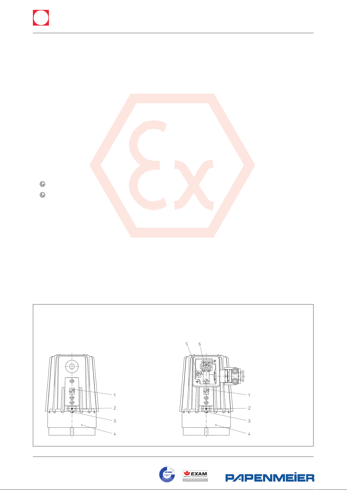
a) Version I (with cable tail)
- the electric cable is fitted ready for use at manufacturers
works.
- the external safety conductor terminal (item 1) must be
connected to a separate grounding point on the plant
- the cable must be supported within 1 m of entry gland.
-Warning: when changing cable (e.g. for another length)
the internal wiring must be disconnected before
unscrewing the cable entry gland
b) Version II (with terminal box)
- select a cable corresponding to cable entry gland M20 x 1.5
and temperature rating according to type plate
- remove terminal box lid. Loosen screws (and anti twist
tabs) on cable pull-out preventer clamp on cable gland
assembly. Feed in cable and retighten screws
- connect cable cores to Ex terminal block (6); safety
core to terminal – internal (5). External ground terminal (1)
must be connected to separate ground point on plant
- fit terminal box cover gasket and refit cover
• Lamp Exchange:
- switch off power
- allow sufficient time to cool as indicated on identity plate
- loosen socket screw (2) which releases locking tab (3) to
screwed lens ring (4)
- unscrew lens ring (4) but only with special claw spanner
- withdraw defective lamp; 2 pin is pulled out;
GZ 10 bayonet type twisted and pulled out
- holding new lamp (use only genuine replacement part) by
its protective material (never with bare fingers) insert into
socket, pushing in carefully in case of 2 pin; twist and push
in case of bayonet type (ensure correct seating)
- refit lens ring (4) and screw in until tight (compression of
O ring seal)
- safety locking tab (3) must engage in appropriate notch so
that lens ring (4) is locked in position
- retighten locking screw (2)
- reconnect power
• Warning:
When changing lamps ensure that the light beam remains
evenly distributed over the lamp glass, as designed. On no
account should a “hot spot” be allowed to develop
externally to the luminaire (e.g. caused by lamp mis-
positioning or as a result of lamp condition)
1 Safety/ground
terminal – external
2 Locking screw
3 Safety locking tab
4 Screwed lens ring
1 Safety/ground
terminal – external
2 Locking screw
3 Safety locking tab
4 Screwed lens ring
5 Safety/ground
terminal – internal
6 Ex terminal block
• Version I (with cable tail EEx d)
- cable entry gland; with pressure tight resin cast
connecting cable (Sinotherm 110 H05GG-F 3G 1.5 mm2)
- safety/ground conductor terminal fitted to luminaire
body internally; additional terminal fitted to outside
of body
• Version II (with terminal box EEx de)
- cable entry gland: M20 x 1.5
F.H.Papenmeier GmbH & Co. KG · division Lumiglas
Talweg 2 · 58239 Schwerte · GERMANY
phone: +49-2304/205 0 · fax: +49-23 04/205 206
e-mail: info.lumi@papenmeier.de
www.lumiglas.de
lumiglas
lumiglas
®
All dimensions in mm unless stated otherwise. Subject to change without prior notice.
Min 01.07 0093.012.96
Using the hinged mounting bracket the luminaire is
mounted on the cover flange of the circular sightglass fitting
or flow indicator or on the slotted cover nut of the screwed
sightglass. Alternatively: on a screwed sightglass mounting
with flanged adapter collar is possible.
• The Lumiglas luminaire model USL06-Ex, using the
appropriate mounting bracket or adapter collar, suits the
following nominal sizes of sightglass:
• Mechanical installation:
Unit fitted as combined light and sight port.
Fitting DIN 28120 using hinged bracket.
Unit fitted to screwed sightglass used as light port only;
mounted by means of flanged adapter collar.
• Mounting example:
• Mounting with hinged bracket
The hinged bracket serves to secure the luminaire to the
cover flange of a circular sightglass unit (also of a flow indi-
cator) or the slotted cover nut of screwed sightglass similar
to DIN 11851.
The bracket is fixed using the M8 screw supplied, and a
blind hole drilles and tapped on the bolt pitch circle of the
cover flange face. Alternatively the bracket can be welded
on.
• Mounting with flanged adapter collar:
The adapter is mounted onto (screw – or weld connection)
the slotted cover nut (DIN 11851).
• Replacement parts:
a) for both versions
PartCat. No.
- screwed lens ring (light exit) 1774.033.00
- reflector, Spot 5904.047.00
- reflector, Flood 5904.048.00
- O ring seal (Viton) 0862.039.00
- lamp socket G4(2 pin) 1202.011.00
- lamp socket GY6.35 (2 pin) 1202.012.00
- lamp socket, GZ 10 1202.024.00
b) for Version I (with cable tail)
PartCat. No.
- Cable entry gland complete with
- 2 m connecting cable 1084.013.00
- 5 m connecting cable 1084.015.00
- 10 m connecting cable 1084.016.00
- 20 m connecting cable 1084.017.00
c) for Version II (with terminal box):
PartCat. No.
- flat gasket for cover 0.854.058.00
- trumpet cable entry gland assy 9108.008.00
• Filament lamps (Halogen):
PartCat. No.
- 12 V/20 W – GY6.35 3232.240.00
- 24 V/20 W – G4 3232.206.00
- 24 V/20 W – G4 (reflector, spot) 3232.222.00
- 12 V/35 W – GY6.35 3232.232.00
- 12 V/50 W – GY6.35 3232.238.00
- 24 V/50 W – GY6.35 3232.242.00
- 230 V/50 W – GZ10 3232.261.00
Type of fitting from Hinged bracket Flanged
DN adapter collar
Circular sightglass fitting
DIN 28120 50 … + –
DIN 28121 50 … + –
Flow indicator 50 … + –
Screwed sightglass 65 – +
fitting 80 + +
similar DIN 11851 100 + +
125 + –
• Accessories: claw spanner (for lens ring) Cat. No. 6805.001.00
• Servicing:
- keep luminaire clean
- after opening of luminaire, lightly lubricate thread of
lens ring (4) (e.g. with AEMA-SOL 6B, manufactured by
A. E. Matthes).
- note mean figure for lamp life!
- use only genuine replacement parts!
F.H.Papenmeier GmbH & Co. KG · division Lumiglas
Talweg 2 · 58239 Schwerte · GERMANY
phone: +49-2304/205 0 · fax: +49-23 04/205 206
e-mail: info.lumi@papenmeier.de
www.lumiglas.de

Popular Lantern manuals by other brands

Conrad 110419 operating instructions

Conrad

Conrad 110419 operating instructions

HOLOPHANE MILWAUKEE LANTERN Installation and maintenance manual

HOLOPHANE

HOLOPHANE MILWAUKEE LANTERN Installation and maintenance manual

4M PAINT YOUR OWN LANTERN quick start guide

4M

4M PAINT YOUR OWN LANTERN quick start guide

Sealite SL-70 Installation & service manual

Sealite

Sealite SL-70 Installation & service manual

Sealey AK435 instructions

Sealey

Sealey AK435 instructions

Nave 52124 manual

Nave

Nave 52124 manual

Techko SJL-641 user manual

Techko

Techko SJL-641 user manual

VIPOW URZ0020 user manual

VIPOW

VIPOW URZ0020 user manual

Coleman 2000000859 operating instructions

Coleman

Coleman 2000000859 operating instructions

Eaton i-P65 Plus Instruction leaflet

Eaton

Eaton i-P65 Plus Instruction leaflet

esotec Stone 40 Using instructions

esotec

esotec Stone 40 Using instructions

Coleman BG 800L manual

Coleman

Coleman BG 800L manual

Coleman 2000002663 quick start guide

Coleman

Coleman 2000002663 quick start guide

Intermatic Malibu LZ414 instructions

Intermatic

Intermatic Malibu LZ414 instructions

BEGA 24 231 Instructions for use

BEGA

BEGA 24 231 Instructions for use

WHITECROFT LIGHTING Aerial Industry installation instructions

WHITECROFT LIGHTING

WHITECROFT LIGHTING Aerial Industry installation instructions

Mobern Lighting RDIS SERIES installation instructions

Mobern Lighting

Mobern Lighting RDIS SERIES installation instructions

V-TAC VT-1607 Installation instruction

V-TAC

V-TAC VT-1607 Installation instruction

manuals.online logo
manuals.online logoBrands
  • About & Mission
  • Contact us
  • Privacy Policy
  • Terms and Conditions

Copyright 2025 Manuals.Online. All Rights Reserved.