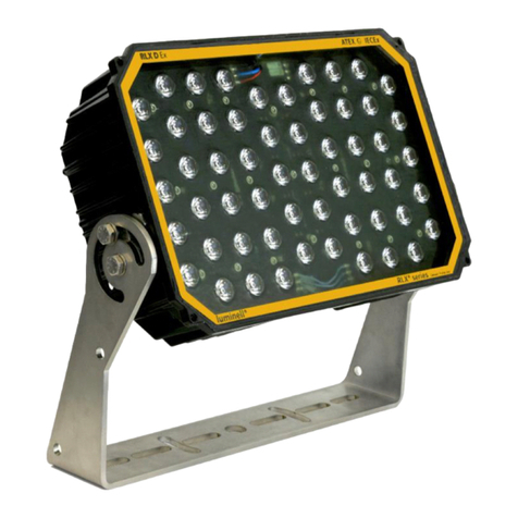
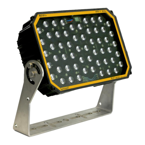
LUMINELL RLX CxZ1.21 User manual

Luminell Norway AS Doc. Nr.: D0011 RLX CxZ1.21 User Manual v1.5
Page 1 of 9
RLX CxZ1.21 - User Manual
KEY FEATURES
-Compact and low weight
-Powerful light performance
-Flicker-FREE, 100% constant light
-Crafted for demanding marine and
offshore conditions
-Remarkable EMC/EMI characteristics
-No maintenance, no flame path
Contents
1GENERAL 2
2SAFETY 2
3TYPES OVERVIEW 2
4MARKING 3
5CERTIFICATE 3
6CONTENT 3
7SPECIFICAIONS 3
8MECHANICAL INSTALLATION 3
9ELECTRICAL INSTALLATION 5
10 TEMPERATURE PROTECTIVE DEVICES 6
11 MAINTENANCE 6
12 TROUBLE SHOOTING 6
13 APPENDIX 7

Luminell Norway AS Doc. Nr.: D0011 RLX CxZ1.21 User Manual v1.5
Page 2 of 9
1GENERAL
The RLX CxZ1.21 is a compact and solid LED floodlight created to last in very harsh and corrosive
environments. It is designed to be used both in gas and dust environments, zones 1, 2, 21 and 22.
Read this user guide to get the most out of your RLX CxZ1.21 LED floodlight and help it to maximize its
potential for your application.
2SAFETY
Inappropriate or unauthorized use or failure to comply with the information contained in these
instructions, voids any warranty and may invalidate the certificate. Modifications or changes to the
equipment are not allowed.
The following must be observed:
•national safety regulations
•national workplace health and safety regulations
•national installation and set-up regulations
•generally accepted engineering standards
•the safety information contained in these operating instructions
•the data and rated operating conditions
•disposal of waste, parts or floodlight in accordance with national regulations
•the ATEX or IECEx certificate
•the equipment is suitable for harmful or corrosive chemicals that may be
present
For the installation and operation of explosion-protected equipment, the
recognized rules of technology in accordance with EN60079-14 “Configuring and
selection”, and EN60079-17 “Test and maintenance”, and the accompanying
installation and operating instructions must be observed. Luminell reserves the
right to make technical changes to the product without notice.
3TYPE OVERVIEW
RLX Cx Type and
Power consumption
Temperature Class
and rating
Input Voltage
Light Beam Alternatives
160 W
T3 -55°C ≤ Ta ≤ 55°C
T4 -55°C ≤ Ta ≤ 40°C
VAC:
100 - 277 VAC 50-60 Hz
VDC:
100-300 VDC
-Spot 15
-Medium 40
-Medium 60
-Medium 60 x 40
-Wide 80x60
-Oval 45 x 15
120 W
T4 -55°C ≤ Ta ≤ 55°C
80 W
T4 -55°C ≤ Ta ≤ 55°C
T5 -55°C ≤ Ta ≤ 50°C
40 W
T6 -55°C ≤ Ta ≤ 55°C
Do not open when
energized.
Crush hazard!
Be aware of moving parts
when lifting and mounting
the floodlight. Shall only
be installed by a qualified
electrician.

Luminell Norway AS Doc. Nr.: D0011 RLX CxZ1.21 User Manual v1.5
Page 3 of 9
4MARKING
Identification according to IECEx Scheme:
Identification according to 2014/34/EU (ATEX):
Certificate number: IECEx CML16.0048
II 2G Ex eb mb IIC T3,T4,T5,T6 Gb
II 2D Ex tb IIIC T200,T135,T100,T85 Db
Ta: -55°C ≤ Ta ≤ 40,50,55°C
Certificate number: CML16ATEX3108
Ex eb mb IIC T3,T4,T5,T6 Gb
Ex tb IIIC T200,T135,T100,T85 Db
Ta: -55°C ≤ Ta ≤ 40,50,55°C
5CERTIFICATE
Online link to certificate: www.luminell.com/downloads
6CONTENT
Box content:
Required tools:
•Fully assembled
RLX CxZ1.21 LED floodlight
•User Manual
•Recyclable cardboard
•Allan Key 5mm
•Flat screwdriver (2mm slot)
•2x 17mm combination spanners
•22,24 and/or 30mm combination spanner
•Wire stripper
•Additional cable glands (optional)
7SPECIFICATIONS
Voltage Input
AC: 100-277 VAC 50-60Hz
DC: 100-300 VDC
Current
160W: 0.8 A @ 230 VAC
Power factor
cos <0.95
Consumption
40, 80, 120 or 160 W
Ambient Temperature
-55°C ≤ Ta ≤ 40,50,55°C
IP rating
IP66/67
Weight
9,7kg (21,4 lbs.)
Cable glands
2x M25 Cable glands
2x M20 Blind caps
Light beam angle, temperature class and power variation see “Type overview”
7.1 CABLE GLANDS
Make sure to replace unused cable glands with blind caps M20 or M25. Use –55°C to >80°C rated EX
approved cable glands if the blind caps is exchanged. Lower ambient temperature range will be limited to
the temperature rating of the used cable gland. Warranty will be voided if replaced cable glands / blind
caps are not UV and weather resistant. In addition, it is the installers responsibility to ensure that the cable
and cable glands are appropriate for each other and properly sealed. For EMC compliance to MIL-STD461F
Navy Mobil & Army, overall screening must be terminated 360° in the cable gland.

Luminell Norway AS Doc. Nr.: D0011 RLX CxZ1.21 User Manual v1.5
Page 4 of 9
8MECHANICAL INSTALLATION
To attain the long lifetime, please make sure that the heat sink on the back of the chassis has an adequate
passage to allow air to flow freely –this for the highest possible cooling performance.
For detailed mechanical drawings see appendix.
The RLX CxZ1.21 may be mounted in any direction, however it is recommended to point the cable glands
downwards.
8.1 GASKET AND COVER
When removing the back cover on the terminal box
note following;
-There is no fall protection on the bolts apart
from the hold in the gasket.
-Be aware that the bolts may loosen from
the clamp of the gasket, if they are
mechanically pushed.
-Upon mounting, ensure all gasket areas are
free from any foreign objects.
-If the silicone grease has been wiped off,
then add new silicone grease (Loctite
OKS1110 or similar)
-Tighten the 5x M6 bolts with 6 Nm.
8.2 SAFETY WIRE
The holes for safety wire are tested to withstand a 2m fall. It is recommended always to have wires as short
as possible. ONLY use dedicated holes for safety wires. See appendix for detailed drawings.
8.3 ADJUSTING LIGHT BEAM DIRECTION
Due to the variations of beam angle alternatives, it is important to notice the difference
between these and how each beam will illuminate the desired area. It is essential that
the floodlight is mounted and pointing according to the light simulation or as intended.
Visit www.luminell.com or scan the QR code to understand how the different light beam
angles illuminate.

Luminell Norway AS Doc. Nr.: D0011 RLX CxZ1.21 User Manual v1.5
Page 5 of 9
9ELECTRICAL INSTALLATION
Risk of electric shock. Ensure that power is disconnected before carrying out any connections.
Both the power and dimming connection can be parallel (or in-line) connected. If so, ensure
to use suitable cables due to the increased current running through the junction box and
spring terminals.
9.1 CABLE CONNECTIONS
9.1.1 Dimming Connection (slot 7-10)
On the positive and negative DIM wire connection, it is possible to control the floodlight in three different
ways. The dimming range is approx. from 10% up 100% light output.
Interface
All on the same
connection: DIM +/-
Signal specifications
Comment
Resistance
One floodlight: 0-100 kΩ
Several floodlights(n) parallel connected: 100 kΩ/n.
Eg. 4x floodlight controlled together would require a
25 kΩ variable resistor or potentiometer.
It is recommended to use logarithmic resistors, since
the sensitivity is greatest when resistance is small. If
nothing is connected the output is 100%
Very simple to set up. Requires
no external electronics, only
cable and a variable or fixed
resistor(s). Resistant to
electromagnetic disturbance.
0-10 V
External low voltage supply up to 10 VDC.
Very common method for DIM
control. The RLX CxZ1.21 has a
built-in delay for stable and
reliable control and resistance
to electromagnetic
interference.
4-20 mA
External constant current source. Adjusting the
current from 4-20mA at a nominal voltage of 24
VDC. Only one floodlight per 4-20mA controller.
Not affected by
electromagnetic disturbances.
9.1.2 Startup current
A startup current is needed to energize the electronics inside the RLX CxZ1.21 LED floodlight. When using a
MCB16 Type C fuse, approx. 20 RLX CxZ1.21 floodlights can be started at once. The inrush current is the
equal for all power alternatives.
Function
Symbol and position
Nr.
Description
Wire cross section
Power Grid
Connection
L (1,2)
Phase
0,2 <6mm2
N (3,4)
Neutral
conductor
0,2 <6mm2
PE (5,6)
Earth
connection
0,2 <16mm2
DIM connection
See 9.1.1
DIM + (7,9)
Positive DIM
0,1 <2,5mm2
DIM -(8,10)
Negative DIM
0,1 <2,5mm2
ONLY Luminell
battery backup
Acc. Connection
(Separate
product)
+ (11)
LED/PSU
positive
0,1 <2,5mm2
- (12)
LED/PSU
negative
0,1 <2,5mm2
C (13)
Control signal
0,1 <2,5mm2
N(14)
Temperature
sensor
0,1 <2,5mm2
More illustrations in appendix

Luminell Norway AS Doc. Nr.: D0011 RLX CxZ1.21 User Manual v1.5
Page 6 of 9
10 TEMPERATURE PROTECTIVE DEVICES
For hazardous safety and lifetime optimization the RLX CxZ1.21 LED floodlight is equipped with several
temperature protective devices. Two individual temperature controls may have influence on the use of the
floodlight.
Automated Temperature Control
A set of temperature sensors are distributed on the LED circuit board to
protect the LED and material lifetime in high ambient temperatures. This
circuit will automatically adjust the LED current as the temperature rises. It
is important to note that this circuit will not have influence on the light
output before the temperature reaches material limits. See table.
Manual Resettable Temperature Protection
The floodlight is equipped with a manual resettable temperature protective device, which will trigger and
turn off the lamp if it is heated with an external heat source or if another fatal error occurs. For the
protective device to reset, the power input must be turned OFF and ON and the temperature must be
decreased.
11 MAINTENANCE
The product is made to be maintenance free and only occasional cleaning without solvent is recommend to
ensure light output and cooling.
Do not paint. Material combination and surface treatment has been carefully selected to make the RLX
CxZ1.21 floodlight withstand corrosive environments even with damage to the surface treatment. The
assembled unit complies with ISO9223/12944 and has a rated C5m corrosion class.
Damages to seals, gasket, breather drain, cable glands, entries, front glass, housing or terminals may
invalidate the certificate. In uncertain cases, please contact Luminell for clarification.
12 TROUBLE SHOOTING
Problem
Possible reason
Possible solution
Does not turn on.
The floodlight may be exposed to external
heat, causing the temperature protection
to activate.
Remove external heat source
and disconnect and reconnect
power. See 10 Temperature
protective devices.
Turns off
automatically
A combination of high ambient
temperature and reduced airflow may
cause the floodlight to heat up and turn
off.
Disconnect and check for
sufficient air flow.
Seems to have
reduced light
output.
High ambient temperature (see Ch. 10) or
an unintended DIM signal or connection
on the DIM connections.
Check ambient temperature
and dim control connection.
RLX CxZ1.21
Type
100% light
output
160 W
Ta <40 °C
120 W
Ta 55 °C
80 W
40 W

Luminell Norway AS Doc. Nr.: D0011 RLX CxZ1.21 User Manual v1.5
Page 7 of 9
13 APPENDIX
13.1 DIMENSIONS

Luminell Norway AS Doc. Nr.: D0011 RLX CxZ1.21 User Manual v1.5
Page 8 of 9
3.
4.
13.2 MOUNTING AND CONNECTION
13.3 ACCESSORIES
See Luminell.com for all available accessories
1. 1002322 Pole Mount bracket Ø30-Ø100
2. 251 Protection Guard Set
3. 1002629 Retrofit bracket 130, 160 to 225-260, 350-380, 435
4. L0433 Oil Damper Single Bracket Assembly
1.
2.

Luminell Norway AS Doc. Nr.: D0011 RLX CxZ1.21 User Manual v1.5
Page 9 of 9
13.4 LIGHT BEAM ILLUSTRATIONS
Structured glass
Clear glass
Types:
-Oval 45x15
-Medium 60x40
-Wide 80x60
Types:
-Spot 15
-Medium 40
-Medium 60
Table of contents
Other LUMINELL Floodlight manuals

LUMINELL
LUMINELL RLX DxZ1.21 User manual

LUMINELL
LUMINELL RLX E User manual

LUMINELL
LUMINELL SL2 Instruction Manual

LUMINELL
LUMINELL RLX DxZ2.21 User manual

LUMINELL
LUMINELL SL1 Instruction Manual

LUMINELL
LUMINELL RLX D User manual

LUMINELL
LUMINELL RLX Series User manual

LUMINELL
LUMINELL SL1 Instruction Manual