Luminor BLACKCOMB LBH4-Z122 User manual

LBH5-Z22 LBH5-Z122
BL
ACKCOMB
OWNER’S MANUAL
illuminating technologies for life
Operaon & Installaon Instrucons
LB4-Z1
LUMINOR - Rack-Mount Systems
SYSTEM LB4-Z1
LB5-Z1
LB4-Z2
LB5-Z2
LB4-Z12
LB5-Z12
LBH4-Z2
LBH5-Z2
LBH4-Z12
LBH5-Z12
LBH4-Z22
LBH5-Z22
LBH4-Z122
LBH5-Z122
LBH4-Z222
LBH5-Z222
Rated Flow 8.0 GPM 15.0 GPM
1st Filter Sediment
10”
Sediment
20”
Sediment
10”
Sediment
20”
Sediment
10”
Sediment
20”
Mesh
strainer 10”
Sediment
20”
2nd Filter N/A N/A Carbon
20” N/A Carbon
20”
Carbon
20”
Sediment
20”
Scale
reduction 20”
3rd Filter N/A N/A N/A N/A N/A N/A Carbon
20”
Carbon
20”

2|Page
Congratulaons on purchasing this LUMINOR UV system.

3|Page
TABLE OF CONTENTS
Safety Consideraons......................................................................................................... 4
Before You Begin ................................................................................................................ 5
Water Quality Parameters.................................................................................................. 5
Assembly ............................................................................................................................ 6
Conguraon Overview...................................................................................................... 7
System Sizing ...................................................................................................................... 8
Locaon.............................................................................................................................. 8
Orientaon ......................................................................................................................... 9
Installaon ....................................................................................................................... 10
System Preparaon .......................................................................................................... 13
Cleaning the Quartz Sleeve .............................................................................................. 13
Cleaning the UV Sensor .................................................................................................... 14
Cleaning the Mesh Strainer.............................................................................................. 14
Operaon ......................................................................................................................... 15
BLACKCOMB4.1 Controllers ..................................................................................... 16
BLACKCOMB5.1 & BLACKCOMB6.1 Controllers ......................................................... 16
BLACKCOMB5.1 & BLACKCOMB6.1 Power-up Sequence ........................................... 16
BLACKCOMB5.1 Operaonal Screens....................................................................... 17
BLACKCOMB6.1 Operaonal Screens....................................................................... 17
Lamp Countdown Sequence.................................................................................. 18
System Service Suggested...................................................................................... 19
Lamp Replacement (BLACKCOMB4.1 systems) ........................................................ 19
Lamp Replacement (BLACKCOMB5.1 & BLACKCOMB6.1 systems) ............................ 19
QR Codes ............................................................................................................... 19
System Troubleshoong......................................................................................... 20
Temperature Management Devices ................................................................................. 21
Expansion Modules .......................................................................................................... 22
BLACKCOMB Rack-Mount UV System Specicaons........................................................ 23
Limited Warranty Statement:........................................................................................... 24
Warranty Registraon ...................................................................................................... 25

4|Page
Safety Consideraons
It is important that care is taken when operang and/or maintaining your system.
Please read the instrucons
• The appliance is not to be used by persons (including children) with reduced physical,
sensory or mental capabilies, or lack of experience and knowledge, unless they have
been given supervision or instrucon.
• Children should be supervised so that they do not to play with the appliance.
• WARNING: Do not operate the UV-C emier when it is removed from the appliance
enclosure.
• The appliance is to be supplied through a residual current device (RCD) having a rated
residual operang current not exceeding 30 mA.
• This appliance contains a UV-C emier.
• Unintended use of the appliance or damage to the housing may result in the escape of
dangerous UV-C radiaon. UV-C radiaon may, even in lile doses, cause harm to the
eyes and skin.
• The appliance must be disconnected from the supply before replacing the UV-C emier.
• The appliance is intended to be permanently connected to the water mains and not con-
nected by a hose-set.
• Maximum working voltage of built-in UV driver U-OUT=240V
• If the supply cord is damaged, it must be replaced by the manufacturer, its service agent
or similarly qualied persons in order to avoid a hazard.
• Before servicing this equipment, disconnect the power cord from the electrical outlet.
• Energy given o by the UV lamp is harmful to your eyes and skin. NEVER look directly at
an illuminated UV lamp without adequate eye protecon and always protect your skin
from direct exposure to the UV light.
• For complete disinfecon**, use ONLY genuine replacement parts.
• Do not operate the unit if it has any damaged or missing components.
• To avoid possible electrical shock, use only with a properly grounded electrical outlet.
• Never perform any maintenance to the system unless you are comfortable in doing so.
Contact the manufacturer for service instrucons if required.
• Do not use this system for any purpose other than what it was intended for. Misuse of
this system could potenally cause harm to the user or others.
• Your system is intended to be installed indoors and away from leaking plumbing. DO NOT
plug the unit in if the system or any of the components are wet.
• The system should be directly installed into a ground fault circuit interrupter (GFCI). If
the use of an extension cord is required, the cord must be manufactured with a mini-
mum of 16 gauge wire and care should be taken to avoid potenal tripping hazards.
• We recommend that a licensed plumber or cered technician install the system.

5|Page
Before You Begin
The following will be needed for installing the UV system:
Tools
• Pipe cuer, hacksaw or other specialized tools required to cut into your exisng
plumbing (e.g. if you have PEX piping)
• Soldering tools (torch, ux, emery cloth and solder)
• Wrench (for ghtening ngs)
Other Materials
• Inlet/outlet connecons
• Teon™ tape
Water Quality Parameters
Treated water should be tested for at the least the parameters listed below. If the water exceeds
the listed parameters LUMINOR strongly recommends that appropriate pretreatment equip-
ment be installed (equipment required will depend on parameters being treated):
Hardness: <7 gpg (120 mg/L) – if hardness level is 7 gpg or slightly below the
quartz sleeve must be cleaned periodically in order to ensure e-
cient UV penetraon; if above the water must be soened.
Iron (Fe): <0.3 ppm (0.3 mg/L)
Manganese (Mn): <0.05 ppm (0.05 mg/L)
Turbidity: < 1 NTU
Tannins (organics): <0.1 ppm (0.1 mg/L)
UVT (transmiance): >85% (Please contact LUMINOR if water has a UVT that is less than
80% for pre-treatment recommendaons)
You can have your water tested at a private analycal laboratory or by your local dealer. It is
always recommended to install pre-ltraon of at least 5 microns prior to a LUMINOR UV disin-
fecon** system.
**LUMINOR’s systems are tested for reducon of the MS-2 coliphage challenge microorgan-
ism to demonstrate a log reducon greater than or equal to the reducon caused by a dose
of 40mJ/cm2.

6|Page
Assembly
The BLACKCOMB rack-mount UV system is designed as a do-it-yourself (DIY) system with a single
inlet and outlet port. Unpack the system and ensure all the components are included in the box.
Your system is shipped with the following components:

7|Page
LBH5-Z22
LB4-Z1
LBH5-Z222LBH5-Z122
Conguraon Overview

8|Page
System Sizing
All LUMINOR UV systems are rated for a specic ow rate in water that meets the quality param-
eters on page 5. PLEASE NOTE that increasing the ow above this rang or disinfecng** water
that does not meet the quality parameters will decrease the dose and therefore compromise the
ecacy of the system. To determine the ow rate, follow these simple steps:
1. Be sure no water is being used in the home.
2. Open a faucet or tap nearest the pressure system and run unl the well pump starts.
3. Close the faucet and using a second hand watch, record the length of me in seconds unl the
pump stops. This is known as the cycle me.
4. Then using a container of known volume, preferably in US Gallons, open the faucet or tap
nearest the pressure system and measure the amount of water drawn o unl the pump starts
again. Depending on the size of the container used, it is acceptable to turn the faucet on and o
to empty the container. This measurement is known as the draw down.
To calculate the pressure system ow rate divide the draw down by the cycle me and mulply
that by 60.
Draw Down__________÷ Cycle Time____________ x 60=__________Pumping Rate in USGPM
Locaon
Choose a locaon where the main cold water line is accessible. The system must be installed
aer other water treatment equipment (i.e. soener), but before any branches (See Figure 1).
Figure 1. Typical Installaon

9|Page
PLEASE NOTE: All LUMINOR UV disinfecon** systems are intended for indoor use only as they
should not be exposed to the elements. A ground fault circuit interrupter (GFCI or GFI) outlet is
required.
Orientaon
This system has the ambidextrous capability of being able to have the main water inlet enter
from either the le hand side or right hand side of the unit. The units comes pre plumbed from
the factory for a le hand water inlet. To change to a right hand water inlet follow these simple
steps (See Figure 2):
Step 1: Remove the lter sump housings (either one, two, or three housings depending on the
model purchased) from the lter head and set aside.
Step 2: Remove the lter head screws from the top mounng plate.
Step 3: Carefully lower the lter head(s) from the rack assembly and rotate 180 degrees. Re-
assemble onto the rack assembly and take note of the arrows located on the top of the lter
head(s) indicang water ow (which now should be indicang a ow direcon of right-to-le).
Step 4: Remove the stainless steel UV reactor from the two plasc clamps located on the top
of the rack. Carefully remove the top straps securing the reactor with the aid of a standard (slot)
screwdriver). Rotate the reactor 180 degrees (with the inlet now facing to the le and the lamp
connecons located towards the right) and place back into the cell clamps and re ax the two
top straps.
In either the le or right conguraons, to facilitate lamp removal, ensure there is enough space
at the lamp connector end to safely remove the UV lamp and/or quartz sleeve (See Figure 3).
Figure 2. System Orientaon (water inlet)

10|Page
Installaon
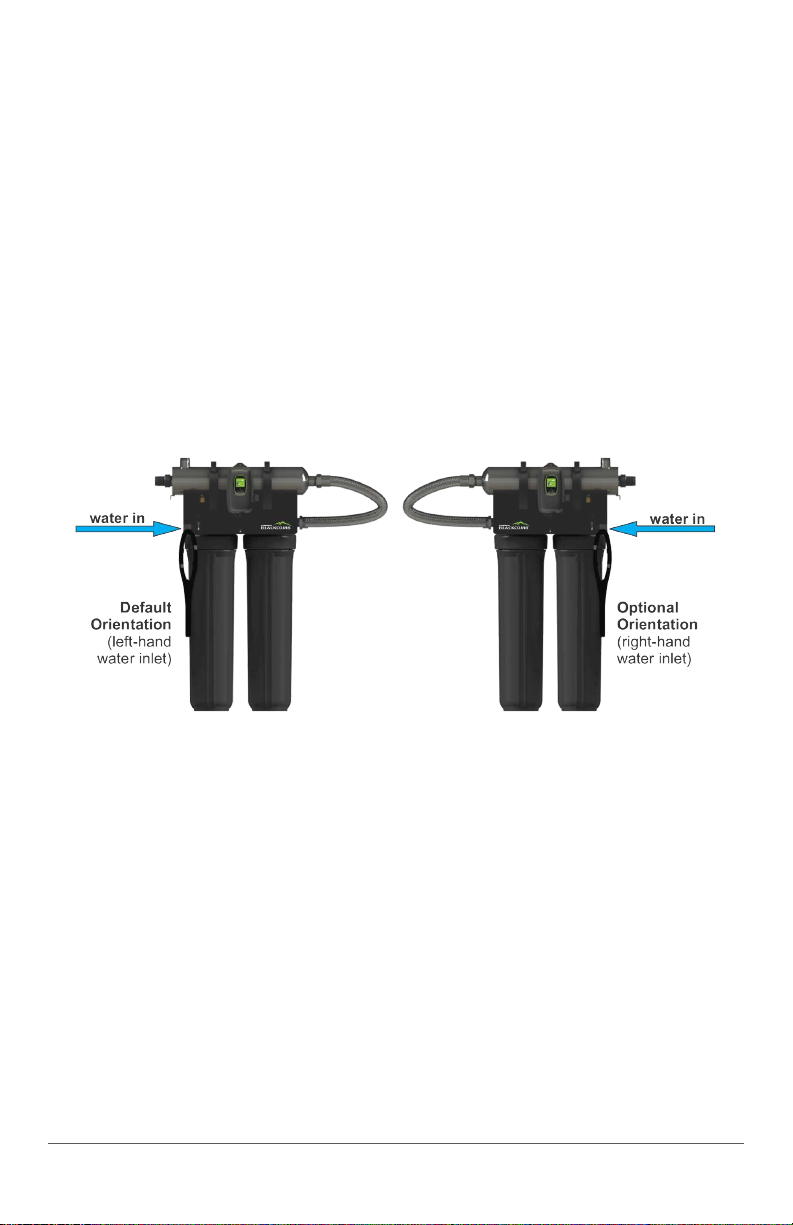
Step 1: Once both the orientaon and locaon have
been selected, securely fasten the rack to a suitable back-
ing. As the rack system is extremely heavy when lled
with water, it is imperave that the rack be mounted with
suitable fasteners for the parcular installaon. Mounng
to a drywall backing is not suitable, unless the rack is fas-
tened directly to the wall studs.
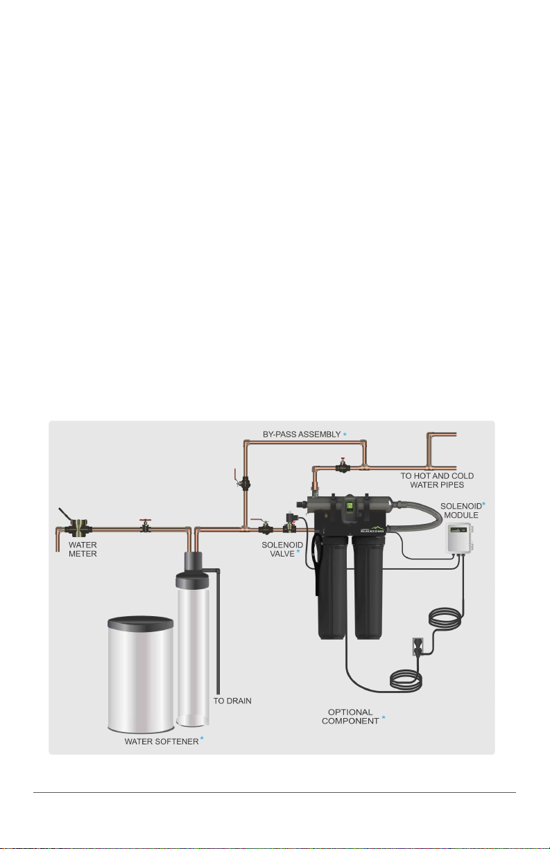
Step 2: The use of a by pass assembly is recommended
as it will allow you to isolate the UV system This will allow
for easier access in case maintenance is required.
Step 3: For water supplies where the maximum ow rate is unknown, a ow restrictor is rec-
ommended so that the rated ow of your parcular BLACKCOMB system is not exceeded. The
ow restrictor should be installed on the inlet port of the reactor.
Step 4: It is recommended to have a licensed plumber connect the UV reactor to the water
supply and may be a requirement depending on where you are located.
Step 5: Connect both the inlet and outlet to the rack system with the applicable connecons
based on your parcular plumbing requirements. The inlet port of the lters is a 1” FNPT connec-
on and the outlet port of the UV reactor is a 1” MNPT connecon.
Step 6: Once the system has been plumbed in, gently remove the
quartz sleeve from its packaging being careful not to touch the length
with your hands. The use of coon gloves is recommended for this pro-
cedure as oils from the hands can leave residue on the sleeve and lamp
which can ulmately block the UV light from geng to the water.
Carefully slide the sleeve into the reactor unl you can feel it hit the
opposite end of the reactor. Align the sleeve so it centered along the
length of the reactor, then gently push it in to lock it into the internal
centering springs in the far side of the reactor. CAUTION: Pushing too
hard when the sleeve is not aligned can damage the centering springs.
Slide the o-ring onto the sleeve unl it is bued up against the reactor
(See Figure 4).
Figure 4. Quartz
Sleeve Installaon
Step 7: Hand ghten the provided gland nut over the quartz sleeve onto the threaded end
of the reactor. It has a posive stop to prevent over-ghtening. A rm force may be required to
fully ghten the gland nut, but DO NOT USE TOOLS for this step. Insert the provided stainless
steel compression spring into the quartz sleeve. The spring works with the lamp and LUMI-Loc™
connector to create the proper lamp alignment. PLEASE NOTE: DO NOT install a UV lamp inside
the quartz sleeve without the sleeve spring in place.
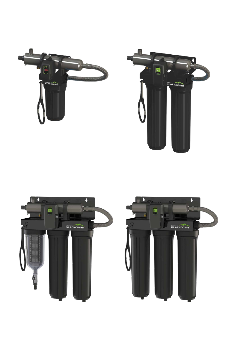
Step 8: Install the lter cartridges in their appropriate housings. For the BLACKCOMB branded
products, please refer to the BLACKCOMB Rack-Mount UV System Specicaon chart. PLEASE
NOTE: This chart indicates the correct cartridge posion for the default “le-hand” orientaon
with the water inlet located on the le side of the rack system. If the orientaon was switched,
the cartridge placement must also be switched. Once the cartridges are in place, use the sup-
plied lter wrench to “snug” the lter housing onto the lter head (See Figure 5).
Figure 3. Lamp Removal
Spacing

11|Page
Figure 5. Cartridge Removal
Step 9: Install the oponal UV sensor (purchased separately). Align the at poron so it faces
the gland nut end and matches up with the half metal lip on the sensor port (see Figure 6). Insert
the sensor so it is fully seated and hand ghten the sensor nut. Insert the sensor connector into
the IEP port located on the right side of the controller (Figure 7). For the sensor to be recognized
by the controller, the controller power must be plugged in last. Do not plug the controller power
cord in before the last step.
Figure 6. UV Sensor Installaon Figure 7. IEP Connecon
Step 10: The system is now ready for water ow. When all plumbing connecons have been
completed, slowly turn on the water supply and check for leaks. Make sure the bypass valves are
funconing properly and that the water is owing through the system. The most common leak
is from the o-ring not making a proper seal on the reactor. For new installaons, review steps 6
and 7. For older systems drain the reactor, remove the o-ring, dry it and reapply silicon grease.
Reinstall the o-ring ensuring that it is properly sealed against the reactor and check again for
leaks. To help vent the pressure from the system while the system is lling up with water, it is a
good idea to twist open the pressure relief valve located on the top of the lter head. Close the
valve once water appears at the port. If the system has two lters, perform this funcon on the
housing closest to the water inlet rst and then on the next lter in sequence.
Step 11: Always hold UV lamps by their ceramic ends, not by the lamp quartz. Remove the lamp
from its packaging. Again, the use of coon gloves is recommended. Remove the lamp key from
the lamp’s connector and set it aside for the next step. Be careful to not touch the key’s exposed
contacts. Insert the UV lamp into the reactor, being careful not to drop it.

12|Page
Step 12: Install the lamp key into the controller (BLACKCOMB5.1, BLACKCOMB6.1 systems only).
The key always comes packaged with the lamp and sits on the connector. With the key removed
from the lamp, orient it so the label is upright and facing you. The key will plug into the lamp key
port on the right side of the controller (Figure 9).
Step 13: Plug the LUMI-Loc™ lamp connector into the lamp. Note the keying for proper align-
ment (see Figure 8a, 8b). Insert the lamp connector into the gland nut and turn the connector
approximately ¼ turn to lock the connector to the gland nut as in Figure 10.
Figure 9. Lamp Key Installaon Figure 10. LUMI-Loc™ Connector
Step 14: Tighten the capve ground screw to the ground lug on the UV reactor to ensure proper
grounding.
Figure 11. Ground Screw Connecon
Step 15: Ensure all connecons are sealed prior to pressurizing system, including factory
connecons.
Step 16: Your system is now ready to be plugged into the appropriate GFCI protected outlet.
Refer to the following secon before any water is allowed to ow through the system.
Note: Installaon of your BLACKCOMB disinfecon** systems
shall comply with applicable provincial/state & local regulaons.
Figure 8a. Standard Output UV
Lamp Connecon
Figure 8b. High Output UV
Lamp Connecon

13|Page
System Preparaon
With a new installaon, or any me the UV system is shut down for service, without power, or
is inoperave for any other reason, the lines in the home or facility could be contaminated. Use
the following steps to prepare the lines throughout the enre home or facility.
Step 1: Check for and remove any “dead ends” in the lines throughout the home as these can
harbor dirt and debris. Plug in the UV system and wait unl it is ready for operaon.
Step 2: Remove the lter cartridge from the last sump and ll it with 1-2 cups of household
bleach (most are 5.25% chlorine). Replace the sump and slowly turn on the water supply.
Step 3: At a water outlet, run the water unl bleach can be smelled. Repeat this for all faucets,
toilets, shower heads, refrigerators, outdoor taps, the washing machine, dishwasher, etc. at the
home or facility. Once nished, wait a minimum of 30 minutes before connuing.
Step 4: Reinstall the lter cartridge into the sump and ush the chlorine soluon by opening
all faucets unl chlorine can no longer be detected. Your BLACKCOMB UV system is ready to use.
Cleaning the Quartz Sleeve
Depending on the water quality, the quartz sleeve may require periodic cleaning. At a minimum,
the quartz sleeve should be cleaned on an annual basis. The following steps outline a basic clean-
ing procedure.
Step 1: If a bypass assembly is installed, shut the inlet valve o to prevent water ow through
the system. Otherwise, turn o main water inlet valve (and/or turn o the water pump).
Step 2: Disconnect power cord of UV system from electrical outlet.
Step 3: Release water pressure by opening a downstream faucet and then close the outlet
shut-o valve (if any). If there is no outlet shut-o valve, expect water to drain from the system
as the head pressure in the system will cause the water to ow back down.
Step 4: Remove the capve ground screw from the ground lug on the UV reactor.
Step 5: Remove the lamp connector from the reactor (gland nut) by pushing the LUMI-loc
connector in and turning it ¼ turn counter-clockwise. Disconnect the lamp connector from the
lamp. CAUTION: the lamp may be hot!
Step 6: Being careful to touch only the ceramic ends, remove the lamp out of the reactor.
Step 7: Unscrew the gland nut from the reactor exposing the end of the quartz sleeve.
Step 8: Remove the quartz sleeve and o-ring by gently twisng and pulling the quartz sleeve.
Step 9: Using a so, lint-free cloth or towel wipe the sleeve down using a commercial scale
cleaner (i.e. CLR® or LIME-A-WAY®). This removes scaling or iron deposits that may be on the
outside of the quartz sleeve. Be careful not to get any moisture or liquids inside of the sleeve.
Step 10: Dry the sleeve with separate cloth.
Step 11: Replace the o-ring and slide the sleeve back into the reactor following steps 7 and 8
from the installaon secon of the manual.

14|Page
Cleaning the UV Sensor
Depending on the water quality, the UV sensor may require periodic cleaning. At a minimum,
the UV sensor should be cleaned on an annual basis. The following steps outline a basic cleaning
procedure.
Step 1: If a bypass assembly is installed, shut the inlet valve o to prevent water ow through
the system. Otherwise, turn o main water inlet valve (and/or turn o the water pump).
Step 2: Disconnect power cord of UV system from electrical outlet.
Step 3: Release water pressure by opening a downstream faucet and then close the outlet
shut-o valve (if any). If there is no outlet shut-o valve, expect water to drain from the system
as the head pressure in the system will cause the water to ow back down.
Step 4: Place something under the reactor to catch any water that may come out of the reac-
tor during the removal of the UV sensor.
Step 5: Unscrew (counterclockwise) sensor nut from the reactor and pull the sensor slowly out
of the sensor port.
Step 6: Holding the sensor in your hand wipe the at poron (sensor face) of the sensor with
isopropyl alcohol using a clean lint-free cloth.
Step 7: Replace sensor following step 9 from the installaon secon of the manual.
Cleaning Mesh Strainer (LBH5-Z122 models only)
This system contains a washable mesh lter that is designed to
prolong the life of your subsequent lters. Actual water quality
will impact required cleaning frequency. The lter is designed
to be cleaned in place without turning o the water supply or
depressurizing the system.
Step 1: Ensure that an appropriate drain line or bucket is be-
low the system. The drain line should be no more than 2m (6)
in length.
Step 2: Open the drain valve for 15-20 seconds. This gen-
erates a pressure-drop in the lter that pushes the cartridge
downward, automacally reversing water ow from the inside
(counter-current) out of the cartridge. This water ow in coun-
ter-current carries parcles and substances deposited on the
cartridge to drain.
Step 3: Close the valve. Aer a couple of seconds, the internal spring will return the cartridge
to its service posion.
Figure 12. LBH5-Z122
system drain port

15|Page
If contaminaon is signicant, the above steps may not be sucient to fully clean the lter car-
tridge. In this case:
Step 1: Shut o water ow upstream and downstream of the system.
Step 2: Open the drain valve and vent(s) to drain the water from the system.
Step 3: Open the lter by unscrewing the sump from the head using the supplied wrench.
Step 4: Remove the cartridge, being careful not to lose the spring.
Step 5: Clean the cartridge under a jet of cold water and use a so brush to remove impuries.
Step 6: Insert the clean cartridge back in the sump.
Step 7: Screw the sump to the head.
Step 8: Close the vent(s) and drain ports.
Step 9: Slowly open the inlet valve into the system, then open the outlet valve once the sys-
tem is pressurized.
If any damage is observed on the lter, it should be replaced.
Filter Housing Drain Plug
In order to remove all water from the lter housing, unscrew the drain plug
from the underside of the housing.
Filter housing
drain plug
Operaon
BLACKCOMB systems come with a feature laden controller that incorporates both the lamp driv-
er (ballast) and control features in one water-ght case. Four main controllers are available for
the BLACKCOMB systems (depending on your model). All four models feature a power factor
corrected, constant current lamp driver with a universal power input.
Please Note: While the LED or display screen is red and the buzzer is sounding the water from
the system should NOT be consumed. If any water does pass through the system during this
period, please follow the disinfecon** procedure as outlined in this manual before the water
is consumed. For BLACKCOMB4.1 and BLACKCOMB5.1 systems, even though they have a visual
and audible warning built into the controller, a green LED or status screen does not necessarily
indicate that the water coming from this system is in fact potable (safe to drink). These systems
do not measure the level of disinfecon**; they simply measure the “on-o” status of the lamp.
Please have your water checked for microbiological contaminants on a regular basis.

16|Page
BLACKCOMB4.1 Controllers
LB4
Series
LBH4
Series
Simplisc in operaon, these systems feature a tri-colour
LED that indicang system status and a 4-digit display to
indicate lamp life remaining. Pressing the buon will change
the display to indicate total running me. When the UV lamp
is on and within its operang age, the LED will be green.
When the UV lamp is not on or the lamp life has expired,
the LED will be illuminated red and an audible buzzer will be
sounding. To remedy this condion, the UV lamp must be
replaced with a new genuine LUMINOR UV lamp.
BLACKCOMB5.1 & BLACKCOMB6.1 Controllers
LB5 / LB6
Series
LBH5 / LBH6
Series
A full colour LCD screen provides the user with a detailed
descripon of the system’s performance in addion
to providing any applicable fault messages and system
diagnoscs. The controllers used in both the BLACKCOMB5.1
and BLACKCOMB6.1 are idencal. The dierence is that the
BLACKCOMB6.1 series of products includes a UV intensity
monitor. All BLACKCOMB5.1 and BLACKCOMB6.1 controllers
include an “innite expandability port” located on the right
side of the controller. Simply plug in an oponal UV sensor
module into the expandability port of a BLACKCOMB5.1
controller and the system will now monitor the UV intensity
of the system!
BLACKCOMB5.1 & BLACKCOMB6.1 Power-up Sequence
On start up, the controller will run through a diagnosc start-up and the sequence will be dis-
played as follows on the colour LCD:
Next, the controller checks for and inializes any oponal modules that may be aached to the
system.
Oponal Modules Check
- UV Sensor
- Solenoid
- 4-20 mA
- WIFI
- Remote Alarm
- Flow Meter
OR

17|Page
A nal module screen is displayed showing which specic modules were inialized.
The controller then displays the lamp opmizaon screen for 60 seconds to allow the lamp to
reach its opmum output. Finally, a nal “start-up complete” screen is displayed. The system will
now be ready to disinfect** water ow.
all detected modules lamp reaching max output successful start-up
BLACKCOMB5.1 Operaonal Screens
On systems without the UV monitor, the default screen shows the LUMINOR Home Screen. At
any point during operaon the user is able to scroll through the LUMINOR Home Screen, Lamp
life remaining, QR Code, Contact Info and Maintenance Parts screens by pressing the buon
located on the front of the controller.
BLACKCOMB6.1 Operaonal Screens
On systems with the UV monitor, the system will display the same screens as on the BLACK-
COMB5.1 except the UV Intensity replaces the home screen. The UV Intensity screen displays
the level of UV light detected by the sensor. UV intensity can be aected by poor water quality,
scaling on the quartz sleeve and/or sensor, lamp failure or lamp expiring. The following screens
show the UV Intensity dropping.
Below 56%, the numbers and warning sign turn red and an audible chirp is given by the ballast
every 15 seconds. Below 51%, the screen is solid red and a constant audible alarm is given. This
alternates with a screen indicang “water may be unsafe for consumpon”. With the solenoid
module, the controller de-acvates the solenoid valve, shung o all water ow.

18|Page
audible chirp every
15 seconds
audible chirp every
15 seconds
constant audible
alarm
cycles with red low
UV screen
Lamp Countdown Sequence
The system counts down the number of days unl a lamp change is required.
BLACKCOMB6.1
BLACKCOMB5.1
BLACKCOMB4.1
At thirty days remaining, the LED or display screen will change to a yellow cauon indicator. At
seven days remaining, the system will addionally repeat an audible chirp. Past the zero day
threshold, the LED or display screen changes to solid red with a connuous buzzer.
BLACKCOMB6.1
BLACKCOMB5.1
BLACKCOMB4.1
At any point during this sequence, the audible chirp or alarm can be deferred for seven days by
holding the controller buon down for a period of ve seconds. The number of deferrals used
will be displayed as below. Once the deferral expires, the alarm will sound once again. The de-
ferral can be repeated up to three mes. PLEASE NOTE: At any point aer lamp expiraon, the
water may be unsafe for consumpon and should not be consumed without another form of
disinfecon**.

19|Page
System Service Suggested
BLACKCOMB 5.1 & 6.1 controllers will display the System Service Suggested
Screen every 6 months to remind consumers to maintain both their UV and
other preltraon. This will serve as a prompt only and will not put the
system into alarm. To clear this condion simply press the buon located
below the screen.
Lamp Replacement (BLACKCOMB4.1 systems)
Aer the lamp is expired, it must be replaced with the same part number as indicated by the
label on the reactor. Begin replacing the lamp by unplugging the power for the controller, then
refer to Installaon, starng with step 11 (page 11) for instrucons on installing the new lamp.
To reset the mer in the controller, rmly hold down the buon on the controller for 10 seconds.
The controller will read “rSt3”, “rSt2”, “rSt1” and then beep. The buon can now be released, the
lamp countdown mer has been reset.
Lamp Replacement (BLACKCOMB5.1 & BLACKCOMB6.1 systems)
Aer the lamp is expired, it must be replaced with the same part number as indicated on the
Maintenance Parts screen or on the label on the reactor. With the system powered down, re-
move and discard the lamp key from the controller. The replacement lamp is packaged with a
lamp key on the connector at the end of the lamp. Remove the key from the lamp and place it in
the controller. Refer to Installaon, starng with step 11 (page 11) for instrucons on installing
the new lamp.
QR Codes
A QR code (Quick Response code) is a matrix barcode rst designed for the
automove industry. LUMINOR uses the QR code to store a link to a spe-
cic page on our website. Users with a camera phone equipped with the
correct reader applicaon can scan the image of the QR code and over a
wireless network connect to a LUMINOR web page in the phone’s browser.
LUMINOR’s QR webpage has informaon on how to purchase replacement
components as well as a helpful video directory on system servicing (i.e. How
to change a UV lamp or quartz sleeve). To access the QR code on the BLACK-
COMB controller, press the control buon unl the QR code screen appears.

20|Page
System Troubleshoong
Hard Alarms: The following give a constant audible alarm. If present, the solenoid valve is closed,
and the 4-20, remote alarm and Wi modules transmit the alarm.
System Display Problem Resoluon
The system has detected
a problem with the
lamp.
Reset lamp protecon circuit
-unplug unit for 10 seconds.
Replace the lamp with the
part as indicated on the silver
label on the reactor or on the
Maintenance parts screen.
Although the lamp is
powered and visibly
illuminated, due to the
lamp’s age its UV output
is no longer sucient for
proper disinfecon**.
Replace the lamp with the
part as indicated on the
silver label on the reactor or
on the Maintenance parts
screen.
Low UV Intensity.
Remove and clean the
quartz sleeve and sensor.
Check water quality meets
requirements on page 5 and
add ltraon as required.
Replace lamp.
Wrong lamp or sensor
installed.
Replace component with
proper model as indicated.
The UV sensor is no
longer communicang
to with the system.
Ensure all modules are
connected properly to the
system and to each other.
Modules can be tested indi-
vidually by plugging in one at
a me and cycling power to
the system.
Replace any module that is
not detected when plugged
directly into the controller.
A bad connecon has
been detected in the IEP
port.
Missing or incorrect
lamp key.
Ensure the lamp key
(packed with the lamp, on
the connector) is installed.
Unplug and reinstall the key.
Ensure the key part number
matches Lamp on Mainte-
nance Parts screen.
This manual suits for next models
15
Table of contents
Popular Water Dispenser manuals by other brands

Leaf Home Water Solutions
Leaf Home Water Solutions LWS1.0 owner's manual

Maytronics
Maytronics ecoclear EC 100 Installation & operation manual

ottimo
ottimo 7323498 instruction manual

Crystal Mountain
Crystal Mountain Mogul user manual

ABANTERA
ABANTERA ROM10H20CAT manual

Zojirushi
Zojirushi CD-LCC40 operating instructions

GE
GE GXRTQR installation instructions

Pentair
Pentair filter Owner's/operator's manual

Aquona
Aquona GLACE user manual

EDM Product
EDM Product 76753 instructions

Excalibur Water Systems
Excalibur Water Systems 1.5 " HIGH CAPACITY SIMPLEX WATER SOFTENER Installation and operation manual

BRIO
BRIO Moderna CLPOU730UVRO4 user manual