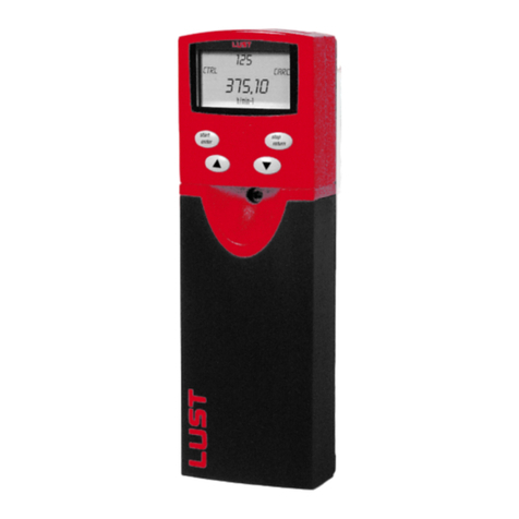
Lust CM-CAN1 User manual

G1
CM-CAN1
Project design, installation and
commissioning of CDA3000 on
the CANLUST field bus
EN
EN
FR
ES
User Manual
Communication Module
CM-CAN1
Before

Overview of documentation
CM-CAN1 User Manual
ID no.: 0916.21B.0-00
Version: May 2000
Applicable as from softwareversion V1.40
We reserve the right to make technical changes.
Before purchase
With shipment
(depending on supply
package)
G1
CDA3000 Catalogue
Selecting and ordering a
drivesystem
Operation Manual
CDA3000
Operating Instructions
KEYPAD KP200 Application Manual
Quick and safe initial
commissioning
Operation via
KEYPAD KP200
Adaptation of drive system
to application
Manual, CANLust
Communication Module
Manual, CANopen
Communication Module
Manual, PROFIBUS-DP
Communication Module
CDA3000 project design,
installation and
commissioning on the
fieldbus
CDA3000 project design,
installation and
commissioning on the
fieldbus
CDA3000 project design,
installation and
commissioning on the
fieldbus
D
E
F1
G1
G2
G3

User Manual CM-CAN1
DE
EN
FR
Dear User,
This manual is intended for you in your role as a project engineer, com-
missioning engineer or programmer of drive and automation solutions
on the CAN field bus. It is assumed that you are already familiar with this
field bus based on appropriate training courses and/or study of the
relevant literature.
We assume that your drive is already in operation – otherwise you should
first refer to the operation manual.
Good luck, and have a nice day!
How to use this
manual
1 General introduction
2 Installation
A
3 Commissioning and configuration
5 Control and reference input
6 Troubleshooting
1
2
3
4 Device parameter setting 4
5
6
Appendix: Glossary, Index
A
7 Examples 7

Pictograms
➢ Attention! Misoperation may result in damage to the
drive or malfunctions.
➢ Danger from electrical tension! Improper behaviour
may endanger human life.
➢ Danger from rotating parts! The drive may start run-
ning automatically.
➢ Note: Useful information.

User Manual CM-CAN1
DE
EN
FR
Table of contents
1 General introduction
1.1 Measures for your safety ........................................1-2
1.2 System requirements ..............................................1-2
1.3 User level in operation over CAN bus .....................1-3
1.4 Further documentation ...........................................1-3
1.5 General information on the structure of a
CAN network ...........................................................1-4
1.5.1 Access rights .......................................................1-4
1.5.2 Size of identifiers .................................................1-5
1.5.3 Time response .....................................................1-5
1.5.4 Transmission speeds ...........................................1-6
1.6 CAN protocol for LUST drives .................................1-7
1.6.1 Device states .......................................................1-7
1.6.2 Device control ......................................................1-8
2 Mounting and connection
2.1 Setting the address .................................................2-2
2.2 Mounting .................................................................2-3
2.2.1 Size BG1...5 (0.37 ... 15 kW) ................................2-3
2.2.2 Size BG6...8 (22 ... 90 kW) ...................................2-4
2.3 Electrical installation ..............................................2-5
2.3.1 Controller enable (ENPO) ......................................2-6
2.3.2 LED status display ...............................................2-6
3 Commissioning and configuration
3.1 Commissioning sequence .......................................3-2
3.2 Commissioning instructions ...................................3-4
3.3 Errors in initialization .............................................3-4
3.4 Test on higher-order controller ..............................3-4

User Manual CM-CAN1
3.5 Data handling ..........................................................3-5
3.5.1 Saving settings ....................................................3-5
3.5.2 Restoring factory defaults ....................................3-5
4 Setting the device parameters
4.1 Representation of parameter data .........................4-2
4.1.1 Data types ........................................................... 4-2
4.1.2 Mapping data types .............................................4-3
4.2 Configuration of the drive unit by way of preset
application data sets ..............................................4-5
4.3 CDA3000 parameters for bus operation ................ 4-6
4.3.1 General bus settings ............................................4-7
4.3.2 Definition of control location and reference
channel ...............................................................4-9
4.3.3 Data backup ......................................................4-11
4.4 Representation of parameter number .................. 4-12
4.5 Telegram execution and verification ................... 4-13
4.6 Parameter channel ...............................................4-14
4.6.1 Reading string parameters .................................4-15
4.6.2 Writing string parameters ..................................4-18
4.7 Downloading
parameter data sets .............................................4-20
5 Control and reference input
5.1 Controller enable (ENPO) ........................................ 5-2
5.2 CAN system states ..................................................5-2
5.3 Device states ...........................................................5-2
5.4 Device control .........................................................5-3
5.4.1 EasyDrive control mode .......................................5-4
5.4.2 Control via DRIVECOM state machine ...................5-6

User Manual CM-CAN1
DE
EN
FR
5.5 Identifiers ..............................................................5-10
5.5.1 Selective transmissions .....................................5-10
5.5.2 Broadcast transmissions ....................................5-11
5.5.3 Station logon ......................................................5-11
5.5.4 System Start/Stop ..............................................5-12
5.5.5 Control functions ................................................5-12
5.5.6 Status messages ...............................................5-14
6 Fault rectification
6.1 Programmable error responses ..............................6-2
6.2 Error messages .......................................................6-4
6.3 Parameterizable warnings on the CAN ..................6-6
6.4 LED status display on the module ..........................6-7
6.5 Acknowledgment of error messages .....................6-7
7Examples
7.1 Activation of a CDA3000 .........................................7-2
7.1.1 EasyDrive control mode .......................................7-2
7.1.2 Control mode: DRIVECOM state machine ..............7-3
7.1.3 Parameter setting ................................................7-5
A Glossary
B Index

User Manual CM-CAN1

User Manual CM-CAN1 1-1
DE
EN
1
2
3
4
5
6
7
A
1 General introduction
1.1 Measures for your safety ........................................1-2
1.2 System requirements ..............................................1-2
1.3 User level in operation over CAN bus .....................1-3
1.4 Further documentation ...........................................1-3
1.5 General information on the structure
of a CAN network ....................................................1-4
1.5.1 Access rights .......................................................1-4
1.5.2 Size of identifiers .................................................1-5
1.5.3 Time response .....................................................1-5
1.5.4 Transmission speeds ...........................................1-6
1.6 CAN protocol for LUST drives .................................1-7
1.6.1 Device states .......................................................1-7
1.6.2 Device control ......................................................1-8
The term “master” as used in the following designates a higher-order
controller which organizes the bus system.
The terms “drive unit” and “slave” as used in the following represent an
inverter or servocontroller.

1-2
User Manual CM-CAN1
1 General introduction
1.1 Measures for
your safety
The CDA3000 inverter drives are quick and safe to handle. For your own
safety and for the safe functioning of your device, please be sure to
observe the following points:
1.2 System
requirements
Any system with a CAN interface is suitable. No requirements are made
in terms of processor speed, since the timeout monitors on the machines
can be adapted to the respective processor performance.
Read the Operation Manual first!
• Follow the safety instructions!
Electric drives are dangerous:
• Electrical voltages > 230 V/460 V:
Dangerously high voltages may still be present
10 minutes after the power is cut, You should therefore
always check that no power is being applied!
• Rotating parts
• Hot surfaces
Your qualification:
•In order to prevent personal injury and damage to prop-
erty, only personnel with electrical engineering qualifica-
tions may work on the device.
•Knowledge of national accident prevention regulations
(e.g. VBG 4 in Germany)
•Knowledge of layout and interconnection with the CAN
bus field bus
During installation observe the following instructions:
•Always comply with the connection conditions and tech-
nical specifications.
•Electrical installation standards, such as cable cross-
section, shielding, etc.
• Do not touch electronic components and contacts (elec-
trostatic discharge can destroy components).

User Manual CM-CAN1 1-3
1 General introduction
DE
EN
1
2
3
4
5
6
7
A
1.3 User level in
operation over
CAN bus
The CAN BUS INTERFACE always operates on a high user level on the
relevant drive unit. The user level corresponds to parameter 1-MODE in
subject area _36KP, but cannot be influenced by way of it. Some of the
parameters at those user levels are service parameters, and are not
documented in the Operation Manuals of the individual devices.
Note: Unintentional write access to such parameters may severely
impair the functioning of the device!
1.4 Further
documentation
• Operation Manual for commissioning of the drive unit
• Application Manual for additional parameter setting to adapt to the
application. The Application Manual can be downloaded as a PDF
file from our website (http://www.lust-tec.de). Follow the Service link.
• Engineering Guide CDA3000
• ISO 11898, Road Vehicles, Interchange of digital information -
Controller Area Network (CAN) for high-speed communication
• CiA/DS20x : CAN Application Layer for Industrial Applications
• CiA/DS 102-1 : CAN Physical Layer for Industrial Applications -
Part 1: Two Wire Differential Transmission

1-4
User Manual CM-CAN1
1 General introduction
1.5 General infor-
mation on the
structure of a
CAN network
Multimaster capability
A CAN network has multimaster capability - that is, any station can
independently send messages on the bus which can be received by any
other station on the bus.
Figure 1.1 Any station can independently send messages.
Typically, however, transmissions are exchanged between two stations on
the bus.
The basic rule is: Anyone can evaluate the information from an identifier,
but only one station per identifier can have transmission rights .
Each transmission is assigned a priority by the selection of the identifier
for that transmission. The priority is antiproportional to the identifier num-
ber - that is, a rise in the significance of the identifier results in fall in the
priority of the transmission. Monitoring of the priorities and the issue of
access rights to the bus is controlled on the hardware side by the CAN
controller.
Note: To operate drive controllers in a network there must be no
overlaps between the identifiers used.
1.5.1 Access rights Access rights to the bus where a number of stations are accessing it
simultaneously are assigned by checking the priorities of the identifiers.
The identifier with the lowest significance has the highest priority, and is
able to continue its transmission in the event of a conflict.
Master
Master
Master
Master

User Manual CM-CAN1 1-5
1 General introduction
DE
EN
1
2
3
4
5
6
7
A
1.5.2 Size of
identifiers
The size of the identifiers corresponds to the standard format, i.e. 11 bit
identifiers. The ’Extended’ format is not supported.
1.5.3 Time response
Note: Transmission of the control protocols by the master in a time
division < 1 ms is not permitted. It may occur that messages
are not processed by the drive unit!
For status messages the sampling time can be freely set by way of a
parameter.
Exceptions:
1. If a 1 is entered in device parameter 04-PROG, the drive unit over-
writes all parameter settings with their default values. In this case the
reply telegram is only sent when the complete parameter list has
been reinitialized. This action can take up to 10 seconds.
2. During read-in of the SMARTCARD no communication with the drive
unit is possible over the CAN bus. This condition lasts up to
10 seconds.
3. If an error state is acknowledged over the CAN bus, a device restart
may result. For more detailed information on this topic refer to
section 6 “Fault rectification”.
Series Control channel Parameter channel
CDA3000 1 - 2 ms < 10 ms
Table 1.1 Time response

1-6
User Manual CM-CAN1
1 General introduction
1.5.4 Transmission
speeds
The CAN bus can be operated at the following Baud rates:
When selecting the transfer rate it should, however, be ensured that the
line length does not exceed the permissible line length for the transfer
rate in question.
The following factors influence calculation of the permissible line length:
• Propagation time of the signal on the line
• Signal propagation time of the optocouplers
• Signal propagation time of the gates
The values specified for the line length already include the signal propa-
gation times in the drive unit. For the control, a signal propagation time
from the bus connector to the control's CAN controller of max. 80 ns is
assumed. If these control values are exceeded, the transfer rate must be
reduced by at least one increment!
Transmission speed Maximum line length over the entire network
500 KBaud 100 m Factory setting
250 KBaud 200 m
125 KBaud 450 m
75 KBaud 770 m
50 KBaud 1000 m
25 KBaud 1000 m
Table 1.2 Transmission speeds

User Manual CM-CAN1 1-7
1 General introduction
DE
EN
1
2
3
4
5
6
7
A
1.6 CAN protocol for
LUST drives
The CAN protocol for LUST drives permits integration of the device in a
CAL network. The identifiers are defined in the devices by setting of the
device address.
After power-on, the drive unit responds cyclically with its logon identifier.
From this identifier the higher-order control can identify which devices are
present on the bus and which addresses have been assigned for the
devices.
Note: It is not permitted to operate two devices with the same
address on one bus.
After the system start the drive unit switches to transmission of the
status message. The control thereby detects that the slave is connected
to the network and is now ready for controlling. For control of the devices,
a protocol for selective control of each drive is available.
A broadcast telegram (System Start/Stop) is provided for synchronized
starting and stopping of all drives.
1.6.1 Device states In contrast to the CAN system state, which describes the status of the
entire bus system, the device states in the various devices of a bus
system may vary.
The device state is determined, firstly, by the selective control commands
over the bus and, secondly, by means of information from the respective
process.
For example, an error in an application results in a change of device state.
In the devices a so-called device state machine is operated which assigns
to each state defined responses to events.

1-8
User Manual CM-CAN1
1 General introduction
1.6.2 Device control There are two modes for controlling the devices over CAN.
In the first control mode the key functions of the device can be activated
directly by way of a LUST-specific control word. This mode is termed
“EasyDrive control mode” in the following.
In the second control mode the drive unit is controlled by way of the
DRIVECOM state machine.
EasyDrive
In direct control mode, specific functions of the device are activated with
the individual control bits. Thus, for example, the STR (Start Clockwise)
function can be selected by setting just one control bit. It is also possible
here to transfer unused control terminals of the drive unit to the control for
other process tasks.
DRIVECOM
To control a drive unit in the second control mode over CAN, the state
machine defined in the DRIVECOM PROFILE no. 20 of January 1994 for
INTERBUS-S must be followed.

User Manual CM-CAN1 2-1
DE
EN
1
2
3
4
5
6
7
A
2 Mounting and connection
2.1 Setting the address .................................................2-2
2.2 Mounting .................................................................2-3
2.2.1 Size BG1...5 (0.37 ... 15 kW) ...............................2-3
2.2.2 Size BG6...8 (22 ... 90 kW) ..................................2-4
2.3 Electrical installation ..............................................2-5
2.3.1 Controller enable (ENPO) ......................................2-6
2.3.2 LED status display ...............................................2-6
Attention: Do not insert or withdraw modules in operation!

2-2
User Manual CM-CAN1
2 Mounting and connection
2.1 Setting the
address
Two possible methods of address assignment
1. By bus address parameter 571-CLADR:
By way of parameter 571-CLADR in subject area _57OP, Option
modules, an address from 0 to 99 can be set. If the setting 0 is
selected in parameter CLADR, hardware coding is enabled.
2. Connector coding via connectors X11 and X12:
By way of the pins on connectors X11 and X12 labeled ADRx, the
device address can be binary coded with PIN 1 in the connector by
soldering-in jumpers. By means of the two connectors an address
between 0 and 7 can be selected.
Attention: The device address coded on the connector is only used if
parameter 571-CLADR is set to 0.
Step Action Comment
1Find out which address is assigned to the
module you are installing. Ask your project engineer.
2
Select the mode of addressing:
• by bus address parameter or
• by coding on connectors X11 and X12
See below
Address setting finished; for further procedure see Installation.
X10 Assignment X11/X12 Assignment
1+24 V 1+5 V
2CAN_GND 2CAN_LOW
3CAN_GND
Example for address 5 Dec: 4 ADR0
5 ADR1
6CAN_GND (as X10/2)
7CAN_HIGH
8 ADR2
9+24 V (as X10/1)
Table 3.1 Pin assignment with a connector coding example
X11
X12
CM-CAN1
H5
+
X10
1
2
CAN-IN/OUT
CAN-IN/OUT
X11
1
2120
22
+5V

User Manual CM-CAN1 2-3
2 Mounting and connection
DE
EN
1
2
3
4
5
6
7
A
2.2 Mounting
2.2.1 Size BG1...5
(0.37 ... 15 kW)
Figure 2.1 Mounting for BG1...5
Step Action Comment
1Make sure the power supply to the drive
unit is cut.
2
Connect the CMxxxx to the drive unit as
shown in Figure 2.1 (A). Use only the slot
at the top.
The module lock must engage
audibly.
The bottom slot is reserved for
the UM-xxxx module.
3Mounting clearance min. 35 mm for addi-
tional/other devices Figure 2.1 (B)
Mounting is finished; for the further procedure see section 2.3 “Electrical
installation”.
H1 H2 H3
X4
X2
X3
WARNING
capacitor disscharge
time >3 minutes.
Pay attention to the
operation manual!
ATTENTION
temps de decharge
du condensteur
>3 min. observer le
mode dèmploi!
!
ANTRIEBSTECHNIK
SN.:
000.000.00000000
Typ:
Netz:
Ausg.:
D-35633Lahnau
X1
L3
U
V
W
RB+
RB
L-
L1
L2
ACHTUNG
Kondensatorent-
ladezeit >3 Min.
Betriebsanleitung
beachten!
12
ANTRIEBSTECHNIK
SN.:
000.000.00000000
Typ:
Netz:
Ausg.:
D-35633Lahnau
klick!
X7
35mm
z
z
z
|
|
CM-xxxx
1
2
,,yyz{{|
,,
yyz
{{|
A
B

2-4
User Manual CM-CAN1
2 Mounting and connection
2.2.2 Size BG6...8
(22 ... 90 kW)
Figure 2.3 Mounting of size BG6...8
Step Action Comment
1Make sure the power supply to the drive
unit is cut.
2Open the device cover.
3
Click the module into the mounting
bracket.
For positioning and orientation refer to
Figure 2.3 (A)
The bracket is part of the
MP-UMCM mounting package
(see Figure 2.2).
4Bolt the bracket onto the bottom slot
position - see Figure 2.3 (B).
The CM module is thereby
placed on its head and the rear
of the module is facing forward.
5Connect the module by the ribbon cable
as shown in Figure 2.3 (C).
The ribbon cable is part of the
MP-UMCM mounting package
(see Figure 2.2).
Mounting is finished; for the further procedure see section 2.3 “Electrical
installation”.
Figure 2.2 Mounting
package
MP-UMCM
L+
L2 RB
L-
L1 L3 UVW
H1 H2 H3
X4
start
enter
stop
return
VAL
Hz
X7
X7
12
ANTRIEBSTECHNIK
SN.:
000.000.00000000
Typ:
Netz:
Ausg.:
D-35633Lahnau
klick!
A
B
C
Table of contents
Other Lust Control Unit manuals
Popular Control Unit manuals by other brands

Desoutter
Desoutter E-LIT BOX V2 Original instructions

AzureWave
AzureWave AW-CB511NF user guide

Honeywell
Honeywell 7800 SERIES installation instructions

Grundfos
Grundfos CU 242 Installation and operating instructions

Autonics
Autonics AiC Series user manual

Aumuller
Aumuller USKM Assembly and commissioning instructions