1-2
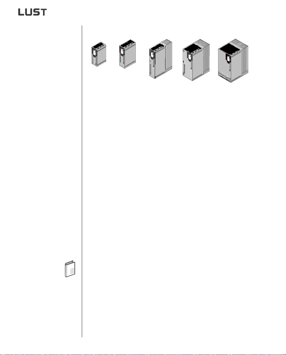
CDD3000-HF Operation Manual
1 Safety
1.2 Intended use Drive controllers are components for installation into electric systems or
machines.
When installed in machines the commissioning of the drive controller (i. e.
startup of intended operation) is prohibited, unless it has been
ascertained that the machine fully complies with the regulations of the
EC-directive 98/37/EC (Machine Directive); compliance with EN 60204 is
mandatory.
Commissioning (i. e. starting inteded operation) is only permitted when
strictly complying with EMC-directive (89/336/EEC).
For the drive controller the harmonized standards of series EN 50178/
DIN VDE 0160 in connection with EN 60439-1/ VDE 0660 part 500 and
EN 60146/ VDE 0558 are applied.
If the drive controller is used in special applications, e. g. in areas subject
to explosion hazards, the applicable regulations and standards (e. g. in
Ex-environments EN 50014 “General provisions” and EN 50018
“Flameproof housing”) must be strictly observed.
Repairs must only be carried out by authorized repair workshops.
Unauthorised opening and incorrect intervention could lead to physical
injury or material damage. The warranty granted by LUST will become
void.
1.3 Responsibility Electronic devices are never fail-safe. The company setting up and/or
operating the machine or plant is itself responsible for ensuring that the
drive is rendered safe if the device fails.
EN 60204-1/DIN VDE 0113 "Safety of machines", in the section on
"Electrical equipment of machines", stipulates safety requirements for
electrical controls. They are intended to protect personnel and machinery,
and to maintain the function capability of the machine or plant concerned,
and must be observed.
An emergency stop system does not necessarily have to cut the power
supply to the drive. To protect against danger, it may be more beneficial to
keep individual drives running or to initiate specific safety sequences.
Execution of the emergency stop measure is assessed by means of a risk
analysis of the machine or plant, including the electrical equipment in
accordance with DIN EN 1050, and is determined by selecting the circuit
category in accordance with DIN EN 954-1 "Safety of machines - Safety-
related parts of controls".
The CDD3000-HF complies with the low voltage directive 73/
23/EEC