Lust SMARTDRIVE VF1000 M Series User manual

Operation Manual
SMARTDRIVE VF1000 · Series M
Frequency inverter 1.1 to 4 kW
stop
return start
enter
VAL
Hz
SMART
CARD
EN
ANTRIEBSTECHNIK

Operation Manual
for static
frequency inverter
1 x 230 V - Version
VF1205M - 1.1 kW
VF1207M - 1.5 kW
3 x 400/460 V - Version
VF1404M - 1.5 kW
VF1406M - 2.2 kW
VF1408M - 3.0 kW
VF1410M - 4.0 kW
Applies as from software edition V 1.2
ID No.: 0809.21B.1-01
Issued January 2001

A-1
Dear customer!
Thank you for the trust which you have placed in us at Lust Antriebs-
technik GmbH by purchasing the SMARTDRIVE frequency inverter.
Installationandcommissioningshouldbecarriedoutbyatrainedengineer.
PleasetakethetimetoreadthisOperationManualcarefullybeforestarting
work. If you follow all the instructions, you will save yourself much time
and many questions during the commissioning stage.
It is essential to read this Operation Manual because both the inverter
itself and further components of the system can be damaged by
improper handling.
If after reading the Manual, however, you still have questions, do please
contract us as given below.
Lust Antriebstechnik GmbH
Gewerbestr. 5-9
D-35633 Lahnau
Phone: +49 64 41 966 - 0
Fax: + 49 64 41 966 - 137

A-2
stop
return start
enter
wait 2 minutes
after mains off
A Useful information on the Operation Manual
The details in this manual apply for all frequency inverters belonging to
the SMARTDRIVE VF1000M family of devices. The housing design is
designated with the letter M for “Medium”.
The Operation Manual consists altogether of 6 chapters, which are listed
under the title “Directly to your goal”.
General information about device versions, safety instructions as well as
CE acceptance test is given.
Chapters 1, 2 and 3 are important for commissioning. Chapters 4, 5 and
6 relate to the operation of the inverter with the control unitKEYPAD KP100
and give information on the individual parameters.
According to the customer-specific requirements on the frequency
inverter, there are also device versions with special functions. The
specifications which deviate from those of the standard device are
marked in the appropriate descriptions.
The following pictograms for warning and instruction occur in the Opera-
tion Manual to improve clarity.
⇒Caution! Danger of death by electrocution.
⇒Caution! It is essential that you follow these instructions.
⇒Caution! Disconnect device from mains and wait 2 minutes to allow
the DC link capacitors to discharge.
⇒Prohibited! Incorrect operation may cause damage to equipment.
⇒Useful information, tip.
⇒Setting with the KEYPAD is alterable.

A-3
Directly to your goal
A Useful information on the Operating Manual......... A-2
A Directly to your goal .................................................... A-3
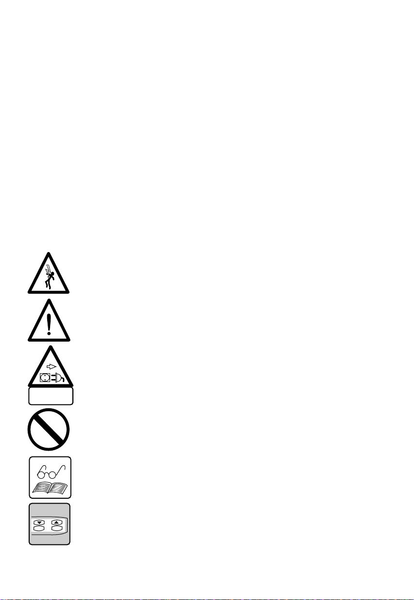
A.1 Safety instructions....................................................... A-5
A.2 Intended use ............................................................... A-5
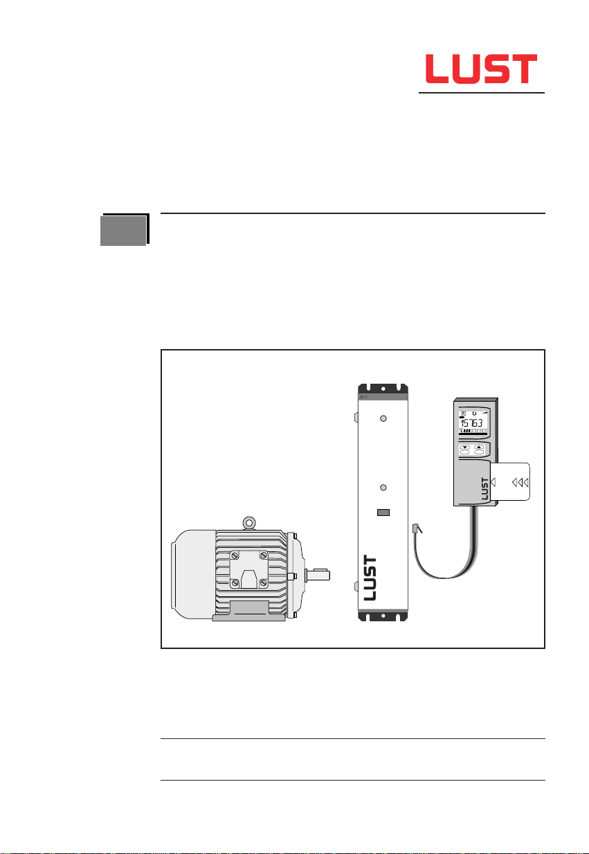
A.3 Design ......................................................................... A-7
A.4 Manufacturer’s declaration for frequency inverter ....... A-8
A.5 VF1000M with CE - acceptance test........................... A-10
A.6 Instructions for correct EMC installation...................... A-12
1 Technical data ........................................................... 1-1
1.1 Assembly and layout plan ........................................... 1-1
1.2 Data table.................................................................... 1-2
1.3 Scale drawing.............................................................. 1-3
1.4 Device assembly ......................................................... 1-4
2 Electrical connections.............................................. 2-1
2.1 Connection plan .......................................................... 2-1
2.2 Fault transmission/fault resistance.(EMC)....................2-3
2.3 Power connections ...................................................... 2-4
2.3.1 Mains connection ........................................................ 2-4
2.3.2 Motor connection......................................................... 2-5
2.3.3 Braking chopper (BR1)................................................ 2-5
2.3.4 Motor temperature monitoring
(Design PTC/PT1)....................................................... 2-6
2.4 Control connections..................................................... 2-7
2.4.1 Specification................................................................ 2-7
2.4.2 Function of the reference input FSINA........................ 2-8
2.4.3 Control functions with STR/STL .................................. 2-11
2.4.4 Control function via S1IND/S2IND/S3IND................... 2-12
2.4.5 MOP function with S1IND/S2IND................................ 2-14
2.4.6 Signal outputs ............................................................. 2-18
2.4.7 LUSTBUS connection (Design C9, C12) ........................ 2-20
2.4.8 INTERBUS-S connection (Design C8)............................. 2-21
2.4.9 CAN-Bus connnection (Design C2)............................. 2-22
3 Operating and error diagnosis ................................ 3-1
3.1 Display ........................................................................ 3-1
3.2 Warning messages...................................................... 3-1
3.3 Error messages........................................................... 3-2
3.4 Motor/inverter-overload protection (I *t monitoring) .... 3-3

A-4
4 Operating the control unit KEYPAD KP100* ............. 4-1
4.1 Layout plan.................................................................. 4-1
4.2 In general .................................................................... 4-2
4.2.1 Menu branches ........................................................... 4-2
4.2.2 Key functions............................................................... 4-2
4.2.3 LCD-display................................................................. 4-3
4.3 Menu structure ............................................................ 4-4
4.3.1 Overview ..................................................................... 4-4
4.3.2 MOP function with KEYPAD KP100............................... 4-6
5 Parameter list ............................................................ 5-1
5.1 Operating level 1 ......................................................... 5-1
5.2 Operating level 2 (Part 1) ............................................ 5-2
Operating level 2 (Part 2) ............................................ 5-3
5.3 Inverter-type dependent and nationally
related parameters ...................................................... 5-4
6 Parameter description .............................................. 6-1
6.1 Reference input........................................................... 6-1
6.2 Actual values............................................................... 6-4
6.3 Frequencies ................................................................ 6-6
6.4 Ramps......................................................................... 6-6
6.5 Characteristics ............................................................ 6-8
6.6 Special functions ......................................................... 6-9
6.7 Signal outlets............................................................... 6-15
6.8 Program functions ....................................................... 6-16
*Accessories

A-5
A.1 Safety instructions
While in operation, inverters may have live, uninsulated, also if required
moving or rotating parts as well as hot surfaces, depending on the degree
to which they are protected.This means that a frequency inverter drive is
a source of potentially fatal injuries.
To prevent serious physical injuries or considerable material damage,
only qualified persons familiar with electrical drive equipment may work
on the device. Only those persons who are familiar with mounting,
installing, commissioning and operating inverters and have appropriate
qualifications shall be regarded as qualified. These persons must read
the Operation Manual carefully before installation and commissioning and
follow the safety instructions.
In this connection, the Standards IEC 364 and CENELEC HD 384 or
DIN VDE 0100 and IEC-Report 664 or VDE 0110 and national accident
prevention provisions or VBG 4 must be respectively observed.
Repairs to the equipment may only be carried out by the manufacture or
by authorized workshops. Unauthorized opening and unprofessional
intervention can result in physical injury or material damage.
A.2 Intended use
Inverters are components that are intended for installation in electrical
systems or machines.They should be basically only used for installation
in control cabinets.
When installed in machines, the inverter may not be commissioned (i.e. it
may not be put to its intended use) until such time as it is established that
the machine corresponds to the provisions of the EC Directive 89/392/
EEC (Machine Directive), EN60204 should be observed.
In addition to the Directive on Low Potential 73/23/EEC the harmonized
standards of the Series prEN 50178/DIN VDE 0160 in conjunction with
EN 60439-1/DIN VDE 0660 Part 500 and EN 60146/DIN VDE 0558 are
applied with regard to inverters.
The technical data and the information concering conditions of connection
can be taken from the type plate and the documentation and are to be
adhered to under all circumstances.

A-6
The inverters should be protected against unauthorised loading. In
particular components may not be bent and/or insulation distances
changed during transport and use.
Inverters contain electrostatically endangered components, which can be
easily damaged when incorrectly handled. Electrical components may
not be mechanically damaged or destroyed.
When work is being carried out on live inverters, the applicable national
accident-prevention regulations (e.g. VBG 4) should be observed.
Electrical installation should be carried out according to the applicable
regulations (e.g. cable diameter, fusing, grounding cable connection).
Additional details are contained in the documentation.
Electronic devices are not intrinsically fail-safe. The user himself shall be
responsible for securing the drive if the device breaks down.
If the inverter is used for special applications (e.g. explosion-proof
area), the required standards and regulations (e.g. EN50014 and
EN50018), must be observed.

A-7
A.3 Design and accessories
The standard design of the VF1000M is only signified on the type plate.
Other deviations from the standard are indicated by the appending of
design codes to the type designation.
Each design code has a special meaning.
Standard order or type designation
Standard design: Painted all metal housing with metal lid for
KEYPAD KP100 installation, protection IP20
With braking chopper power electronics,
without braking resistance in the device
cooling body
Operation Manual
Design code when deviating from standard
The design code is separated with a comma and can be arranged in any
sequence.
Example:
VF1408M, FA, G16
More precise details can be found in the "Data booklet VF1000".
Housing design G16 (IP20)
With built-in mains filter to comply with
the limiting value curve Class A
(Industrial area)
F 1 x x xV
Effective continuous current
Mains voltage: 2 = 230 V
4 = 400/460 V
M range
M
S
MART
D
RIVE
VF1000 product line
F 1 x x xV M ,,,,,

A-8
A.4 Manufacturer’s declaration for frequency inverter

A-9

A-10
A.5 VF1000M with CE - acceptance test
All the inverters described in this Manual have passed the test at the
Carl Schenk AG Test Centre and fulfilled the stated European norms. As
an example, the CE-test certificate for the device VF1207M have been
reproduced. Details of the test itself can be ordered from Lust Antriebs-
technik GmbH.

A-11

A-12
A.6 Instructions for correct EMC installation
According to EMC, means:
The VF1000M inverter series has been so developed, that not only the
Low Voltage Directive is complied with, but also with suitable measures,
the EMC Directives - even strict directives for residential areas can be
observed. The acceptance of the device takes place under laboratory
conditions at the accredited Schenk Commercial Test Centre and is not
bindingly transferrable to a machine or system in its installed condition.
Installationinformation isgiven in the diagram below to aid the achievement
of optimum installation.
You will achieve correct EMC installation ...
1
Necessary cable lengths > 0.3 m
Important: For further information see Chapter 2
-
RB RB +
41
42
43
44
45
46
n.c.
23
29
36
21
22
23
24
25
26
33
34
35
26
47
48
49
50
51
52
RS232/RS485
W V U L3 L1
M
3
K1 SI L1
L2
L3
PE
3 x 400/460VAC
SI
SI
PTC
X6/1 X6/2
X5
X4
X3
X2
X1
... with screened
motor cable
... with screened
control cable
> 10 mm2
Stem point (main
ground) in cabinet
... with screened
control cable
... with screened
control cable
... with screened
motor cable (1
... with mains filter
see Chap. 2.2
... with screened
control cable
,,,
,,
,,
,,,
,,
,
,,
,,
,
,,,
,,,,
,,,
,,
L2

1-1
1 Technical data
1.1 Assembly and layout plan
1LED H2 (green) operation
indicator
2LED H1 (yellow) error indicator
3Terminal X6/1 control outputs
4Terminal X6/2 control inputs
5Terminal X5 for interface design
(RS485/RS232)**
6Terminal X4, for motor PTC**
7Connection socket for X3 for
control unit KEYPAD KP100
8Terminal X2, connection for ext.
braking resistance* and
DC-link coupling (+,-)
W V U PE PE L3
N/L2
L1
-RB RB +
41
42
43
44
45
46
n.c.
23
29
36
21
22
23
24
25
26
33
34
35
26
47
48
49
50
51
52
13
stop
return start
enter
VAL
Hz
SMART
CARD
12
3
6
8
9
2
1
4
11
10
7
5
17
15
SN:----.V--.- --10000
Gerät:
Typ:
Netz:
Ausg:
16
+
14
* Accessories, see data booklet VF1000
** Designs, see data booklet VF1000
9Terminal X1 power connections
10 KEYPAD plug
11 EMC ground clamps for cable
screen
12 Control unit KEYPAD KP100*
13 SMARTCARD* memory card
14 Jumper rail J1 ... J6
15 Connecting point for groun-
ding line
16 Type plate
17 Bus connections (CAN-Bus,
INTERBUS-S, ...)**

1-2
1.2 Data table
Des. Dim. VF1205 VF1207 VF1404 VF1406 VF1408 VF1410
MMMMM M
Output on motor side
Recom. rated power with P kW 1.1 1.5 1.5 2.2 3 4
4 pole standard motor
Device power S kVA 1.9 2.6 2.6 4.0 5.3 6.3
Rated current
1)
(230 V) I
N
A 4.5 6.2 - - - -
Rated current
1)
(400/460 V) I
N
A - - 3.5/3.1 5.5/4.7 7.2/6.3 8.9/7.7
Cont. current
1)
(230 V) 1.1xI
N
A 5.0 6.8 - - - -
Cont. current
1)
(400/460 V) 1.1xI
N
A - - 3.8/3.4 6.0/5.1 7.9/6.9 9.8/8.5
Overload current
1)
for 60s 1.5xI
N
A 6.8 9.3 5.3/4.7 8.3/7.7 10.8/9.5 13.3/11.6
Voltage U V 3 x 0...230 3 x 0 ... 400/460
Rotary field frequency f Hz 0...400
Frequencydefinition f % 0.1 of FMAX (0.05 Hz min.)
Load type - - ohmic/inductive
Short circuit proof - - at the terminals
Ground-fault proof - - according to each mains in.
Input on mains side
Mains voltage U V 1 x 230 +15/-20% 3 x 400/460 +10/-15%
Mains frequency f Hz 50/60 +/- 10%
Connectiondiameter A mm² max. 2.5
Recom. fusing I AT 1 x 16 1 x 16 3 x 10 3 x 10 3 x 16 3 x 16
Assymetry of mains volt. U % - 3 maximum
General
Operatingmode - - 2 quadrats (4 quadrats)
2)
Peak braking power
2)
P
Sp
kW 1.65 max.
Cyclical braking mode
2)
P
eff
W90
Power loss
3)
P
V
W 65 82 80 100 120 150
Efficiency
3)
η%959595959595
Ambient conditions
Cooling air temperature T °C 0 ... 40 (to 1000 m and NN)
Ventilation type - - Convection force-ventilated
Relative air moisture - % 15 ... 85 not saturated
Power reduction in relation
to cooling air temperature -
∆P
T
-
2.5
% /°C
(in range 40 ... 50 °C)
Power reduction in relation
to the installation height
∆P
H
-
5
%
per 1000 m (in range 1000 ...2000 m and NN)
Permissible vibration - - 2 g (IEC 68-2-6)
Mechanics
Weight (without packaging) - kg 3.75
Protection - - IP20, VBG4, NEMA 1
Installation - - upright wall mounting
1) based on the switching frequency of the end level of 8 kHz
2) only with BR1 design
3) with rated voltage and rated current

1-3
E
CD
stop
return start
enter
VAL
Hz
SMART
CARD
B
A A F
F1
G
H
KP100
3)
1.3 Scale drawing
Dimension table
Device type A B C D E F F11) GH
VF1205M...VF1404M 32.5 4.8
φ
330 315 69 260 112 40 245
VF1406M...VF1410M 32.5 4.8
φ
3442) 315 69 260 112 40 245
All dimensions in mm
1)For level assembly see Chapter 1.4 Device assembly
2)
Devices have a fan on their bottom side, also applies for
allVF1000M devices equipped with integrated mains filter
3)Accessories see data booklet VF1000

1-4
1.4 Device assembly
In general:
The installation site must be free from conductive and corrosive
substances as well as dampness. Frequency inverters are intended for
installation in cabinets with external air through-flow.They are fixed with
4 M4 screws on a mounting plate.
It is essential that the minimum distances above and below the device
are observed to avoid overheating. The ventilation opening on the top
side may not be covered or blocked under any circumstances.
The arrangement of several devices in a row is permissible.
Caution:
It should be ensured that foreign bodies such as drilling chips or screws
do not drop into the device during installation of the inverter.This could
result in destruction of the device.
Installation distances:
Among other factors, the size of the cabinet
is related to the power losses of the inverter
(see power table). In order to avoid over-
heating in the cabinet, it is essential that the
appropriate installation distances are
observed. This guarantees safe long-term
operation.
A = 100 mm
B = 50 mm
Level assembly:
Under special installation conditions
it is possible to install the device level
with the heat sink mounted against
the wall. For this purpose the two
supporting brackets must be re-
mounted according to the drawing.
Exception:
Level installation is not possible with
VF1406M, VF1408M,VF1410M and
with all VF1000Ms with integrated
network filter design
A
A
stop
return start
enter
VAL
Hz
stop
return start
enter
VAL
Hz
,
,
B
B
+
+
+
+
+
+
,
,
,
,

2-1
2 Electrical Connections
2.1 Connection plan
wait 2 minutes
after mains off
VF1205M
VF1207M
K1 Example of mains protection
connection
Y
Example of connection for ext.
mains filter
Ground line
X EMC ground clamps for easy
installation of cable screen
X1 Power connections
L1,N, Mains connection 1 x 230 V
U,V,W Motor connection 3 x 230 V
X2/ + , - Connection for DC-link coupling
X2/ RB Connection for ext. braking resistor
X3 Socket for
control unit KEYPAD KP100
X4/51, 52 Motor PTC connection
1)
X5/ Connection terminal for
47,48,49,50 interface RS485
1)
or RS232
1)
X6 Des. Control connections
21 UR Ref. voltage 10 V
for ref. pot.
22 FSIN Freq. ref. input
23 Ground Control unit ref. point
24 STR Start clockwise input
25 STL Start counter-clockwise input
26 UV Control voltage 24 V DC
29 SOUTF Digital freq. output
33 S1IND Prog. digital input
34 S2IND Prog. digital input
35 S3IND Prog. digital input
36 SOUTA Prog. analog output
41 S1OUT Break contact of relay 1
42 Cent. spring of relay 1
43 Make contact of relay 1
44 S2OUT Break contact of relay 2
45 Cent. spring of relay 2
46 Make contact of relay 2
1) Terminal assignment depends on design ordered
Attention:
Startingtorque
ofterminalX1
andX2
max.0,4-0,5Nm
-
RB RB +
41
42
43
44
45
46
n.c.
23
29
36
21
22
23
24
25
26
33
34
35
26
47
48
49
50
51
52
-
+
SOUTA
S2OUT
S1OUT
SOUTF
FSIN
UR
+24V
+10V
STR
STL
S1IND
S2IND
S3IND
V
DD
GND
A
B
RS485
1)
RB1
1)
KP100
PTC
1)
UV
X6X6
X5
X4
X3
X2
X1
001
WVU
N
L1
M
3
K1
SI
L1
N
PE
1x230VAC
Y
X
X

2-2
X6 Des. Control connections
21 UR Ref. voltage 10 V
for ref. pot.
22 FSIN Freq. ref. input
23 Ground Control unit ref. point
24 STR Start clockwise input
25 STL Start counter-clockwise
input
26 UV Control voltage 24 V DC
29 SOUTF Digital freq. output
33 S1IND Prog. digital input
34 S2IND Prog. digital input
35 S3IND Prog. digital input
36 SOUTA Prog. analog output
41 S1OUT Break contact of relay 1
42 Cent. spring of relay 1
43 Make contact of relay 1
44 S2OUT Break contact of relay 2
45 Cent. spring of relay 2
46 Make contact of relay 2
K1 Example of mains protection
connection
Y
Example of connection for ext.
mains filter
ground line
X EMC ground clamps for easy
installation
of cable screen
VF1404M
VF1406M
VF1408M
VF1410M
wait 2 minutes
after mains off
X1 Power connections
L1,L2,L3 Mains connection 3 x 400/460 V
U,V,W Motor connection 3 x 400/460 V
X2/ + , - Connection for DC-link coupling
X2/ RB Connection for ext. braking resistor
X3 Socket for
control unit KEYPAD KP100
X4/51, 52 Motor PTC connection
1)
X5/ Connection terminal for
47,48,49,50 interface RS485
1)
or RS232
1)
1) Terminal assignment depends on design ordered
Attention:
Startingtorque
ofterminalX1
andX2
max.0,4-0,5Nm
-
RB RB +
41
42
43
44
45
46
n.c.
23
29
36
21
22
23
24
25
26
33
34
35
26
47
48
49
50
51
52
-
+
SOUTA
S2OUT
S1OUT
SOUTF
FSIN
UR
+24V
+10V
STR
STL
S1IND
S2IND
S3IND
V
DD
GND
A
B
RS485
1)
RB1
1)
WVUL3
L2
L1
M
3
K1
SI
L1
L2
L3
PE
3x 400/460VAC
SI
SI
KP100
PTC
1)
UV
X6/1X6/2
X5
X4
X3
X2
X1
X
001
Y
X
This manual suits for next models
6
Table of contents
Other Lust DC Drive manuals
Popular DC Drive manuals by other brands

Somati system
Somati system 1RM1 instruction manual

Seagate
Seagate Decathlon 850 product manual

Leadshine Technology
Leadshine Technology OY STEPPER DM556 user manual

Lenze
Lenze E84AVHCE HighLine C Series Mounting instructions

Fujitsu
Fujitsu FP-1000 installation guide

Honeywell
Honeywell CORE Drive quick start guide