LuxCam IP LDA-A720/4 User manual

2 Mega Pixel
Water-Proof IP Camera
User Manual
Please read this instruction carefully for correct use of the product

Before use this product
Before operation, we strongly advise users to read this manual and keep it
properly for using later.
There may be several technically incorrect places or printing errors in this
manual. The updates will be added into the new version of this manual. The
contents of this manual are subject to change without notice.
When this product is in use, the relevant contents of Microsoft, Apple and
Google will be involved in. The pictures and screenshots in this manual are
only used to explain the usage of our product. The ownerships of trademarks,
logos and other intellectual properties related to Microsoft, Apple and Google
belong to the above-mentioned companies.

IP CAMERA USER MUANUAL
Table of Contents
1Introduction.........................................................................................................1
1.1 Summarization.........................................................................................................................1
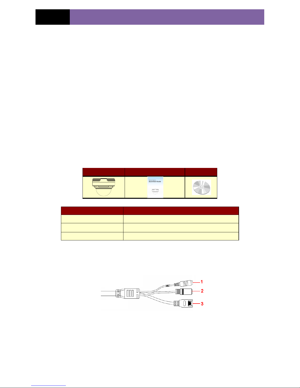
1.2 Check Package Content.............................................................................................................1
1.3 Connection ..............................................................................................................................1
2Installation ..........................................................................................................2
2.1 Install IP-CAM to Ethernet Network....................................................................................2
2.2 Install CMS......................................................................................................................2
3IE Remote Access.................................................................................................4
3.1 LAN................................................................................................................................4
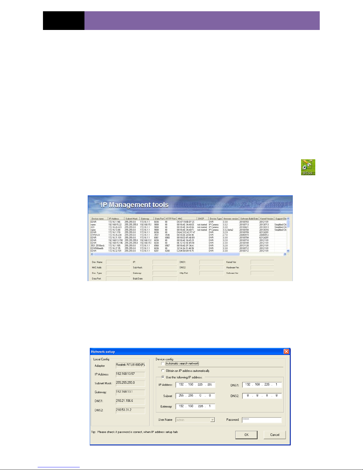
3.1.1 Access through IP-Tool .......................................................................................4
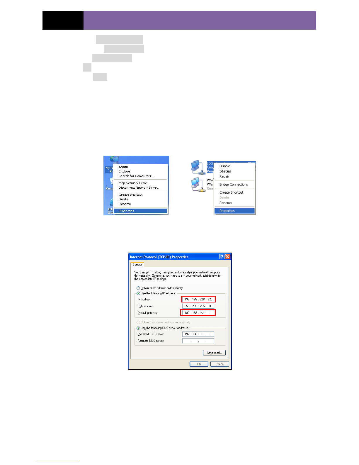
3.1.2 Directly Access through IE...................................................................................5
3.2 WAN...............................................................................................................................7
4Remote Preview ...................................................................................................8
4.1 The Remote Preview Interface ............................................................................................8
4.2 Record Playback ...............................................................................................................8
4.3 Right-click Function..........................................................................................................9
4.4 Snap Pictures....................................................................................................................9
5Remote Live Surveillance...................................................................................11
5.1 System Configuration ...................................................................................................... 11
5.1.1 Basic Information ............................................................................................. 11
5.1.2 Date & Time Configuration................................................................................12
5.2 Video Configuration ........................................................................................................12
5.2.1 Camera Configuration .......................................................................................12
5.2.2 Video Stream...................................................................................................13
5.2.3 Time Stamp .....................................................................................................13
5.3 Alarm Configuration........................................................................................................14
5.3.1 Motion Detection Area ......................................................................................14
5.3.2 Motion Detection Trigger...................................................................................14
5.3.3 Motion Detection Schedule ................................................................................15
5.4 Network Configuration ....................................................................................................16
5.4.1 Port.................................................................................................................16
5.4.2 Wired..............................................................................................................16
5.4.3 NET Traversal Configuration..............................................................................17
5.4.4 Server Configuration.........................................................................................18
5.4.5 IP Notify .........................................................................................................18
5.4.6 DDNS Configuration.........................................................................................19
5.4.7 RTSP ..............................................................................................................21
5.4.8 UPNP .............................................................................................................22
5.4.9 Mail Setting.....................................................................................................22
5.4.10 FTP ................................................................................................................23
5.5 Advanced Configuration...................................................................................................24
5.5.1 User Configuration ...........................................................................................24

IP CAMERA USER MUANUAL
5.5.2 Onvif Configuration..........................................................................................25
5.5.3 Security Configuration ......................................................................................26
5.5.4 Configure Backup & Restore..............................................................................26
5.5.5 Reboot Device..................................................................................................27
5.5.6 Upgrade ..........................................................................................................27
6Mobile Surveillance ...........................................................................................28
6.1 Network Configuration ....................................................................................................28
6.2 By Phones with iPhone OS...............................................................................................28
6.3 By Phones with Android OS .............................................................................................38
7Use method for IP-TOOL...................................................................................44
8Q & A................................................................................................................47
9Specification ......................................................................................................49

Page 1
IP CAMERA USER MUANUAL
1Introduction
1.1 Summarization
This device (short for IP-CAM) is designed for high performance CCTV solutions. It
utilizes most advanced technologies, such as video encoding and decoding technology
and complies with the TCP/IP protocol, SoC., etc to ensure this system more stable and
reliable. This unit consists of two parts: the IP-CAM device and central management
software (short for CMS). The CMS centralizes all devices together via internet or LAN
and establishes a sound surveillance system to realize unified management and remote
operation to all devices in one network.
This product is widely used in banks, telecommunication systems, electricity power
departments, law systems, factories, storehouses, uptowns, etc. In addition, it is also an
ideal choice for surveillance sites with middle or high risks.
1.2 Check Package Content
The pictures below are only for reference. Please make the object as the standard.
IP-CAMERA
Quick Start Guide
CD
Accessories
Description
IP-CAMERA
The device without Lens
Quick Start Guide
The Brief instructions of the product
CD
CD-ROM with software and manual
1.3 Connection
Below figures will introduce function of interfaces.
MIC: connect to MIC
DC12V: connect to power supply
LAN: network port; support PoE power supply

Page 2
IP CAMERA USER MUANUAL
2Installation
2.1 Install IP-CAM to Ethernet Network
The connection of digital video server is show below.
Figure 2-1 Connection
User can connect the PC and IP-CAMERA in accordance with above picture. Before
connecting, please connect external devices, and then connect the power.
The connection steps are as shown below:
Step 1: Connect IP-CAM firstly.
Step 2: Internet line connect to Internet transfer equipment or devices
Step 3: Connect power cable to a power outlet.
2.2 Install CMS
You can remotely monitor and manage the device by using client software or IE browser.
This chapter mainly introduces the installation of CMS. In respect of the operation and
monitor setting details, please refer to CMS user manual in CD.
Note: Prior to installing control center software in user’s computer, please make
sure all anti-virus softwares in the computer are closed so that CMS can install
correctly.
System requirement
Supported Operating System:
Operating system
Comments
Windows XP
Windows XP SP2 or most updated patch; Direct 9.0c or above
Windows Vista
Windows Vista; Direct 10. c
Window 7
Window 7 Ultimate
Windows 2003
Windows 2003 serve or Directx 9.0c or above
Windows 2000
Windows 2000 SP4 or Directx 9.0c or above
Computer hardware requirement
Please make sure the software running well and the computer is compatible :
Recommended PC Specification –4 channels

Page 3
IP CAMERA USER MUANUAL
Item
Specification
CPU
Intel Pentium 3.0 GHz orAMD 3000+
Memory
1GB
HDD
160GB
Recommended PC Specification -9 channels:
Item
Specification
CPU
Intel Core 2 Duo 1.8 GHz orAMD Dual core 3800+
Memory
1GB
HDD
250GB
Recommended PC Specification -16 channels:
Item
Specification
CPU
Intel Core 2 Duo 2.2 GHz orAMD Dual core 3800+
Memory
2GB
HDD
250GB
Notice:
The AMD chip hyper-3800+ and X64 series are not tested.
For real-time view at CIF, max 25 channels can be played concurrently.
For real-time view at D1, max 6 channels can be played concurrently.
Installation Process
It is recommended to disable the anti-virus software before the installation of CMS.
1. Run the „Setup.exe‟ from software CD. Then install CMS according to the prompts.
2. After you install this software, double click it to run if necessary.
3. Find the user manual of the control center system from programs. You can operate
this software according to the introduction of this user manual.
If you just want to user IP-tool, there is no necessary to install CMS software. You can
open the CD and find the IP-tool software and double click it to install.

Page 4
IP CAMERA USER MUANUAL
3IE Remote Access
User can connect IP-Cam through LAN or WAN. Here only take IE browser (6.0)
for example. The details are as follows:
3.1 LAN
In LAN, there are two ways to access IP-Cam: 1. access through IP-Tool; 2. directly
access through IE browser.
3.1.1 Access through IP-Tool
Step 1: Make sure the PC and IP-Cam are connected to the LAN and the IP-Tool is
installed in the PC from the CD.
Step 2: Use IP-Tool to modify the network of IP-Cam. Then, double click the
icon on the desktop to run this software as shown below:
After starting IP-Tool and clicking the IP-Cam in the list, user can check the information
of IP-Cam. If you cannot confirm which one is yours, please shut off the electricity of the
IP-Cam and then power on it. When shutting off the power, the device information will
disappear. When powering on, the device information will emerge. Well, this device is the
used device. Right click the device information and select “Network setup”.

Page 5
IP CAMERA USER MUANUAL
For example, the network segment of this computer is 192.168.13.x under the local
config table. So, please modify the IP address, Gateway of IP-Cam which must be in the
same network segment with the computer. Modifying the network, you have to input the
password and click “OK” button to save the setting.
Note: The default user name is: admin. The default password is: 123456.
The new IP address of this device will display after modification.
Step 3: Use the IP-Tool to login the IP-Cam.
Right-click the IP address and select “browse with IE” or double click the device
information. This will let the IE browser to connect IP-Cam as shown below. IE browser
will auto download the Active X control. If the IE browser cannot download the Active
X control, please refer to Q4 of Chapter 8. A login window will pop up after the
installation of the Active X control.
Input user name and password and then click “OK” button to login.
Note: You can also use the modified IP address of the IP-Cam. Input the IP address in
the IE browser bar and then click “Enter” to access IP-Cam. The default user name is
admin. The default password is 123456.
3.1.2 DirectlyAccess through IE
The network service is default as shown below:

Page 6
IP CAMERA USER MUANUAL
IP address: 192.168.226.201
Subnet Mask: 255.255.255.0
Gateway: 192.168.226.1
HTTP: 80
Data port: 9008
When use the IP-CAM for the first time, you should connect the device with the above
default settings.
Step 1: Manual setup the IP address of the PC. The network segment should be as same
as the default settings of IP-CAM. Right click “My Network Places” icon on the
desktopselect “properties” as shown in the left figure. Right click “Local Area
Connection” at the popup window, and then select “property” as shown in the right
figure.
Select “Internet Protocol (TCP/IP)” in the “General” tabsclick “properties”manual
input network address information of the PC in the pop up window.
Step 2: Open the IE browser, input the default address of IP-CAM and confirm, the IE
browser will download Active X control automatically. If IE browser can‟t download
Active X control, please refer to Q4 of chapter 8.
Step 3: After downloading Active X control, the login dialog box will pop up.
Step 4: Input user name and password in the login dialog box and click “OK” button to
enter into the live interface where you can manage the IP-CAM.

Page 7
IP CAMERA USER MUANUAL
3.2 WAN
a.Access through router or virtual server
Step1: Connecting according to above steps in LAN; enter into System
ConfigurationNetwork configurationBasic configuration to setup the port number
as shown in Fig 3-1:
Step 2: Enter into System ConfigurationNetwork configurationIP configuration to
change IP address as shown in Fig 3-2:
Notice: The steps above should be saved after the change of the port and IP address.
Log back in the device with the saved setting.
Fig 3-1 Port setup Fig 3-2 IP setup
Step 3: Enter into the router‟s management interface through IE browser and forward
the IP address and port of IP-CAM in the “virtual server” (the name depends on the
router). Please refer to Fig 3-3:
Fig 3-3 Router Setup
Step 4: Open the IE browser and input its WAN IP and http port to access. The
following steps are as same as “Step 2, 3 and 4” of Chapter 3.1.2.

Page 8
IP CAMERA USER MUANUAL
4Remote Preview
4.1 The Remote Preview Interface
Fig 4-1 Remote Preview
When motion detection alarm is triggered, the people icon turns red.
Click icon to zoom in the preview image to suitable size. Drag the cursor on
the enlarged image to view suitable preview area. Click icon to zoom out the
enlarged image. Click icon to full-screen the live image.
Clicking icon will appear a save path window and the record file can save on
your PC.
Note: On Window 7 and Window Vista, user can not record or snap pictures until UAC
function is disabled. Please refer to following steps: Start—Control panel—User
accounts—Change user account control settings in which user needs to drag the scale to
Always notify end and then click “OK” button to save.
4.2 Record Playback
Click icon and refer to Fig 4-2:
1
People icon
2
Fix size
3
Zoom in
4
Zoom in
5
Zoom out
6
Full screen
7
Start record
8
Playback
9
Snap
10
Enable audio

Page 9
IP CAMERA USER MUANUAL
Fig 4-2 record playback interface
After selecting the record date, the record files will be displayed in the record file list
box. You can double click a certain record file to playback or check a certain file. Then
click Play button to do playback.
4.3 Right-click Function
Clicking right mouse will appear a pull-down list as below:
Stream: There are two options.
Turn off the live: Click this item will close present live
preview.
Enable audio: Enable remote audio transmission. Users can
hear the audio from the IP-CAM.
Full screen: The live preview picture will full-screen display.
Double click or click right mouse to return to the previous
interface. Fig 4-3 Right key sub-menu
Online user: Display the users that access to the device.
System information: Display the device information: device name, firmware version,
software build date, kernel version and hardware version.
4.4 Snap Pictures
1. Select the picture number and then click “Snap” icon as shown in the Fig
4-4:
2. You can snap multiple pictures. Select the picture number from Frame pull down
list box, such as 2, and check “Title” and “Time” to show capture title and time on the
snap pictures simultaneously. Refer to Fig 4-5:
3. Click “Browse” to set saving path. Click “Save” to save pictures to HDD on the
computer. Click “Printer setup” to set the printer and print the snap pictures. Drag the

Page 10
IP CAMERA USER MUANUAL
scroll bar to view all captured pictures.
Fig 4-4 Single Snap
Fig 4-5 Multi-picture Snap

Page 11
IP CAMERA USER MUANUAL
5Remote Live Surveillance
Functions of remote configurations include: System Configuration, Video Configuration,
Alarm Configuration, Network Configuration and Advanced Configuration. User should
firstly select the menu on the left, and then setup the relative parameters. When a user
setup parameters of a certain device, other users can not setup this device.
5.1 System Configuration
The “System configuration” includes two submenus: Basic Information and Date &
Time.
5.1.1 Basic Information
In the “Basic Information interface, user can setup the device name and can also check
the relative information of the server
Setting steps:
1. Clicking the "Config" icon will appear the menu list.
2. Clicking the “Basic Information "will pop up a window as shown in Fig 5-1:
3. Input the name of the device in the "Device name" text box.
4. Press the "Save" button to save the settings.
Fig 5-1 Basic Information Config
Please refer to the following table for parameters and instructions of server basic
configuration.
Parameter
Meaning
Software version
The software of the device
Software build date
The software build date of the device
Kernel version
The kernel version of the device
Hardware version
The hardware version of the device
Mac Address
MAC address of device
Maximum number of user
Support max 4 users to access
Device name
Name of the device.

Page 12
IP CAMERA USER MUANUAL
5.1.2 Date & Time Configuration
Setting steps:
1. Enter into "System Configuration" “Date & Time”. Refer to Fig 5-2:
2. Select “Modify Time ", user can self-define time. Choose "Time Zone" according to
your location.
3. Enable DST to set DST mode and time.
4. Setup time by select the “Synchronize with NTP Server”.
5. Press the "Save" button to save the settings.
Fig 5-2 Date &Time Config
5.2 Video Configuration
Camera Configuration includes three submenus: Camera Configuration, Video Stream
and Time Stamp.
5.2.1 Camera Configuration
Setting steps:
1. Enter into "Video Configuration ""Camera" interface as shown in Fig 5-3:
Fig 5-3 Basic Configuration

Page 13
IP CAMERA USER MUANUAL
2. User can adjust Brightness, Contrast, Hue and saturation of the picture.
3. Select white balance mode.
4. .WDR, Sharpen, denoise, frequency and CVBS format are adjustable.
5. User can also enable the image mirror and image overturn function.
6. Click “Start Repair”button to repair bad point in the image.
7. Press the "Save" button to save the settings.
5.2.2 Video Stream
1. Enter into "Video configuration""Video Stream" to see a interface as shown Fig
5-4:
Fig 5-4 Video Stream
2. Select the resolution of the single frame image at the "Resolution" pull down list.
3. Select the quantity of video per second at the "Frame rate" pull down list.
4. Select the data stream type at the "Bit rate type" pull down list.
5. Set the video quality at the "Video quality" pull down list.
6. Select alarm picture size.
7. Press the "Save" button to save the settings.
5.2.3 Time Stamp
Enter into "Video configuration""Time Stamp" to display the interface as shown
in Fig 5-5:
Fig 5-5 Time Stamp
1. Select Date Format to show in the live image.
Time stamp: time displayed in the live preview pictures. Four items can choose from:
top left, top right, bottom left and bottom right.
2. Press the "Save" button to save the settings.

Page 14
IP CAMERA USER MUANUAL
5.3 Alarm Configuration
Alarm configuration includes three submenus: Motion Detection Area, Motion
Detection Trigger and Motion Detection Schedule.
5.3.1 Motion DetectionArea
1. Enter into “Alarm configuration""Motion Detection Area" to see an interface as
shown Fig 5-6:
2. Move the "Sensitivity" scroll bar to setup the motion trace sensitivity.
3. Check the "Add”, press the "Ctrl" button and move mouse to select the motion
detection area; Select “Erase” and move the mouse to clear all motion detection area.
4. Press the "Save" button to save the settings.
Fig 5-6 Motion Detection Area
5.3.2 Motion Detection Trigger
1. Enter into “Alarm Configuration""Motion Detection Trigger" to display an
interface as shown in Fig 5-7:
2. Check "Enable alarm" check box. Then all functions under this interface will be
activated.
4. Trigger Email: Check “Attach picture” and select email addresses in the “Receival
email address” text box(Email address shall be set first in the Mail config
interface).Then the triggered snap pictures will be sent into those address. User also can
define the subject and content of the email.
5. Trigger FTP: Check “Uploading picture”. Then the triggered snap pictures will be
sent into FTP server address.
Note: Please refer to FTP configuration chapter for more details.
6. Press the "Save" button to save the settings.

Page 15
IP CAMERA USER MUANUAL
Fig 5-7 Motion Alarm Trigger
5.3.3 Motion Detection Schedule
Enter into “Alarm configuration""Motion Detection schedule" interface as shown in
Fig 5-8:
Week schedule
User could set the alarm time from Monday to Sunday for alarm everyday in one week.
Note: The lengthwise means one day of a week; the rank means 24 hours of a day.
Mouse clicks on the pane to set the alarm hours. Green means selected area. Blank
means unselected area.
2."Add": add the schedule for a special day.
3."Erase": delete holiday schedule
Day schedule
User could set alarm time for alarm in some time of special day, such as holiday.
1. Select a date at the "Date" pull down list, press "Add" button to add that date to the
list box on the right side and then move the scroll bar to set the schedule of that day.
2. Select a date in the list box on the right side, and press "Erase" to remove the
schedule on that day.
Press the "Save" button to save the settings.
Note: Holiday schedule is prior to Week schedule.

Page 16
IP CAMERA USER MUANUAL
Fig 5-8 Motion Detection Schedule
5.4 Network Configuration
Network configuration includes ten submenus: Port, Wired, NET traversal Config,
Server Configuration, IP Notify, DDNS Config, RTSP, UPNP, Mail Setting and FTP.
5.4.1 Port
1. Enter into "Network config""Port" to see the interface as shown in Fig 5-9:
Fig 5-9 Port Config
2. Input port number for IE access in the "HTTP Port" textbox.
1. Input the port number for audio & video transmission in the "Data Port" textbox.
5.4.2 Wired
1. Enter into "Network Configuration""Wired" to see a tab as shown Figure 5-10:
Other manuals for IP LDA-A720/4
1
Table of contents
Other LuxCam IP Camera manuals
Popular IP Camera manuals by other brands

Novus
Novus NVIP-1DN3000H/IR-1P-II user manual

switel
switel BSW 100 Easy Cam operating instructions

Digital Watchdog
Digital Watchdog DWC-V6863WTIRW quick start guide

COHU
COHU 3940 IP i-Dome installation manual

Provision ISR
Provision ISR BX-342IP5 user manual

Zee
Zee Z-3020 Installation guide and user's manual