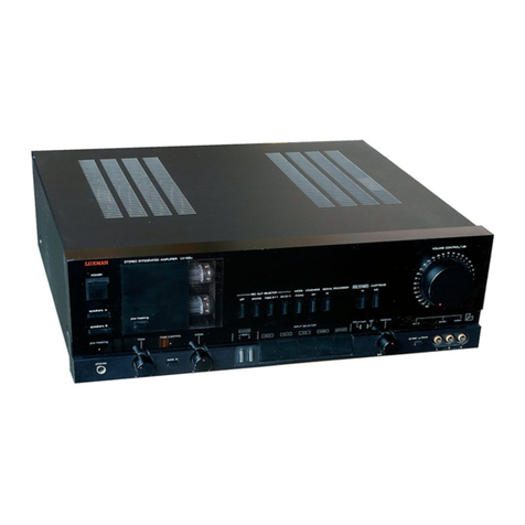
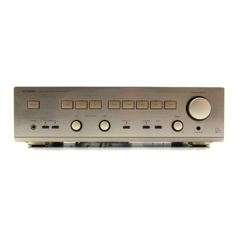
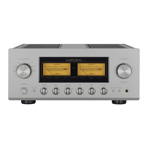
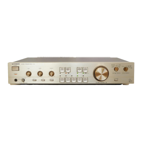
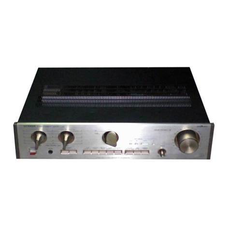
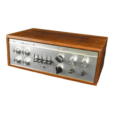
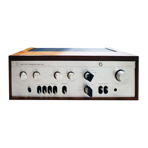
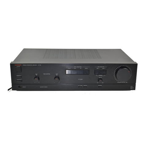
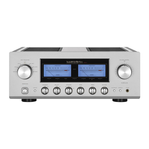
Luxman SQ700X User manual

SOLID
STATE
STEREO
INTEGRATED
AMP
.
OPERATION
MANUAL

NOMENCLATURE
AND
USAGE
OF
EACH
CONTROL
1)
Input
Selector
Switch
This
switch
permits
proper
selection
of
desired
programme
sources.
You
may
set
either
of
the
positions
(PHONO-1,
PHONO-2,
AUX-1,
AUX-2).
Input
selection
shall
be
com-
pleted
by
setting
this
switch
on
the
corresponding
position
to
the
desired
programme
sources
after
connection
of
input.
2)
Treble
Level
Control
,
This
is
level
control
to
vary
the
treble
response.
A
clockwise
turn
of
the
knob
boosts
the
treble
response,
and
counter-
clockwise
decreases
and
cuts
off.
This
knob
has the
click-stopper
of
11
points,
and
yields
flat
frequency
response
at
the
centre
of
rotation
angle.
You
can
choose
a
turn-over
(roll-off)
frequency
at
either
of
2.5iKHz
or
5KHz
with
the
selector
switch
(3).
This
level
control
is
of
independent
structure,
and
permits
separate
control
of
both
left
and
right
channels.
The
left
one
is
for
left
channel
and
the
right
one
for
right
channel.
This
is
convenient
for
adjustment
of
different
levels
between
both
channels
due
to
different
output
of
the
speaker
systems.
1.
INPUT
SELECTOR
SWITCH
2.
TREBLE
LEVEL
3)
Treble
Frequency
Selector
Switch
Treble
turn-over
or
roll-off
frequencies
of
the
treble
level
control(2)
can
be
selected
by
this
switch.
You
may
choose
2
points
(2.5KHz,
5KHz).
By
setting
on
2.5K
Hz
position
you
can
intensify
treble
response
of
tone
contro!
for
the
purpose
of
adjusting
the
treble
end
response
by
leaving
the
mid
range
on
the
flat
response
this
switch
shall
be
set
on
5KHz
position.
4)
Bass
Level
Control
A
clockwise
turn
of
this
knob
boosts
the
bass
response,
while
counter-clockwise
decreases
and
cuts
off.
This
control
is
of
the
same
structure
as
that
of
Treble
Level
Control(2)
and
an
operation
corresponds
to
what
is
expressed
in
(2).
5)
Bass
Frequency
Selector
Switch
Function-wise
this
is
the
same
with
Treble
Frequency
Selector
Switch
expressed
in
(3).
To
intensify
tone
control
effect
it
shall
be
set
on
500Hz
position.
|
6)
Tone
Defeat
Switch
By
setting
this
switch
on
“defeat”
position
a
flat
frequency
response
is
obtained
irrespective
of
the
positions
of
Bass
Level
Control
and
Treble
Level
Control.
8.
MODE
SELECTOR
SWITCH
CONTROL
10.
VOLUME
CONTROL
3.
TREBLE
FREQUENCY
SELECTOR
SWITCH
12.
SPEAKER
SWITCH
13.
TAPE
MONITOR
SWITCH
6.
TONE
DEFEAT
SWITCH
15.
MAINS
SWITCH
5
BASS
FREQUENCY
9
BALARCE
CONTROL
SELECTOR
SWITER
11.
HEADPHONE
JACK
4.
BASS
LEVEL
CONTROL
14.
ATTERUATOR

®
Control
of
Volume
Balance
In
case
of
deviation
between
the
volume
levels
of
right
and
left
channels,
adjust
unbalanced
volume
level
by
the
Balance
Control({9).
A
complete
turn
of
the
knob
to
either
of
clockwise
or
counter-clockwise
direction
causes
to
cut
off
the
volume
of
the
other
end
speaker.
The
volume
balance
of
both
channels
can
be
adjusted
so
that
monaural
disc
sound
reproduced
by
the
stereo
cartridge
under
setting
the
Mode
Selector
Switch
at
the
“stereo”
position
comes
from
the
centre
of
the
right
and
left
channels.
Usually
the
volume
level
of
both
channels
can
be
adjusted
.identical
at
the
centre
click-stop
position
of
the
balancer.
Thus
a
proper
balance
is
established
through
whole
of
playback
stages
from
the
pick-up
to
the
ears
of
listener
through
the
speaker
systems.
If
a
programme
source
may
have
deviation
of
the
volume
level
between
2
channels,
establish
correct
balance
with
this
balancer
in
each
case.
LEFT.CH.
i
:
LEFT
CH.
MODE
roy
|
AF.
AMP.
:
RIGHT
CH.
ys
nf
AF.
AMP.
BALANCER
VOLUME
RIGHT
CH,
by
MODE
™
Tone
Control
The
ultimate
purpose
of
the
audio
system
is
to
make
the
high
fidelity
reproduction
of
programme
sources.
Due
to
difference
of
conditions
and
circumstances
at
reproduction
from
recording
conditions,
and
the
audio
components
it
is
impossible
to
reproduce
the
same
sound
with
the
original
one,
Also
there
is
no
objective
standard
to
judge
good
sound
from
inferior
one.
The
only
possible
solution
is
for
every
listner
to
create
his
favorite
sound
to
match
his
listening
room
according
to
his
own
taste.
It
is
therefore
very
important
that
the
audio
system
offers
such
facility
to
permit
flexible
controls
for
creation
of
the
best
sound.
This
amplifier
is
equipped
with
the
LUX
original
NF
type
turn-over
roll-off
requency
selector
for
subtle
and
minute
control
of
the
reproduced
sound.
Tone
controls
include
Treble
Level
Control(2),
Bass
Level
Control(4},
Treble
Frequency
Selector
Switch(3),
Bass
Frequency
Selector
_
Switch(5).
First
of
all
note
that
if
the
Tone
Defeat
Switch
(6)
is
set
at
the
‘“defeat’’
position
tone
controls
are
not
in
function
yielding
flat
frequency
response
irrespective
of
positions
of
the
tone
control
switches.
In
order
to
be-in
function
of
the
tone
controls
the
Tone
Defeat
Switch(6)
shall
be
set
at
the
“‘in’’
position.
Treble
Frequency
Selector
Switch(3)
has
2
points,
namely
2.5KHz
and
5KHz
and
from
this
point
Treble
Level
Control(2)
starts
to
function.
In
other
words
turn-over
and
roll-off
of
higher
frequency
range
above
this
point
can
be
controlled
by
Treble
Level
~
Contro!(2).
The
position
of
2.5KHz
has
wider
controllable
range
than
5KHz.
Treble
Level
Control(2)
which
functions
in
conjunction
with
Treble
Frequency
Selector
Switch(3)
is
a
tone
control
on
frequency
response
of
high
frequency
range.
It
is
designed
so
that
response
is
flat
at
the
electric
centre
point,
and
a
clockwise
turn
of
the
knob
intensifies
high
frequency
range
while
counter-clockwise
turn
yields
attenuation.
For
easy
adjustment
this
control
is
equipped
with
11
points
of
click
stopper.
This
volume
controls
are
-independent
each
other
and
therefore
convenient
for
adjustment
of
volume
for
right
and
left
speaker
systems.
Bass
Selector
Switch{5)
has
2
points,
namely,
250H
and
500Hz,
and
from
this
point
Bass
Level
Control(4)
starts
to
function.
Tone
control
for
turn-over
and
roll-off
of
lower
frequency
range
is
more
effective
at
higher
frequency,
that
is
to
say,
tone
control
at
500Hz
is
more
effective
than
at
250Hz.
Bass
Level
Control(4)
which
functions
in
conjunction
with
Bass
Frequency
Selector
Switch({5)
is
a
tone
control
on
frequen-
cy
response
of
low
frequency
range.
It
is
designed
so
that
response
is
flat
at
the
electric
centre
point,
and
clockwise
turn
of
the
knob
intensifies
high
frequency
range
while
counter-clockwise
turn
yields
attenuation.
This
control
ts
also
equipped
with11
points
of
click
stopper.
Tone
controls
of
this
amplifier
are
independent
between.
right
and
left
channels,
and
therefore
for
example
in
case
of
feeding
music
for
right
channel
and
voice
for
left
channel
the
tone
can
be
simultaneously
adjusted
in
the
best
manner.For
details
of
these
tone
controls’
characteristics,
refer
to
the
attached
chart
of
response
curve.
BASS
(1)250Hz
(2)
500Hz
;
~
BASS
CONTROL
|
5
1
°
on,
.
4
z
~~
as
ir
1
~
2
TONE
CONTROL
AMP.
PRE,
OUT
“|
TREBLE
CONTROL
[==
a
TREBLE
(1)5KHz
(2)
2.5KHz
TONE
(i)defeat
(2}in
@
Operation
of
Attenuator
This
switch
is
normally
set
at
the
“‘normal’’
position.
If
switched
over
to
the
“attenuate’’
position
attenuator
starts
to
function
and
the
gain
will
be
attenuated
by
18dB
(about
1/8).
Useful
when
subdued
volume
level
is
desired
for
volume
adjustment.
Also
this
can
be
used
as
a
momentary
speaker
silencing
switch.
For
reproduction
in
the
mid-night
with
small
volume
this
switch
is
useful
for
fine
adjustment
of
volume
level.
A
void
switching
over
to
‘‘normal”
at
the
high
volume
level,
since
sometimes
such
momentary
big
sound
is
reproduced
as
may
destroy
speakers.
See
to
it
that
this
switch
is
set
to
the
‘‘normal’’
position
after
using
for
attenuation.

ensures
simultaneous
recording
on
tape
and
playback
of
the
sound
recorded
on
the
tape.
In
this
case
recording
on
tape
and
playback
of
the
recorded
sound
are
practised
at
the
same
time,
and
connection
must
be
made
for
both
functions.
Need
to
connect
the
Recording
Output
Terminals(21)
to
the
Line
Input
Terminals
(AUX
Input)
of
tape-recorder,
and
the
Tape
Monitor
Termi-
nals(22)
to
the
Output
Terminals
(LINE
OUT)
of
the
tape-recorder.
For
connection
the
pin-jack
lead
is
used.
Then
if
the
Tape
Monitor
Switch(13)
is
set
at
the
“source”
position,
original
sound
is
fed
to
the
speakers
and
if
at
the
“monitor”
position,
recorded
one
is
fed
to
the
speakers.
!t
makes
possible
to
compare
the
original
sound
with
recorded
one
by
changing
position
of
the
Tape
Monitor
Switch(13).
Thus
possible
recording
error
can
be
prevented
in
case
of
3-head
tape-recorder.
Incidentally
note
that
reproduction
of
recorded
sound
becomes
a
little
bit
delayed
as
compared
with
that
of
original
sound
since
there
is
a
gap
between
recording
head
and
playback
head.
Simultaneous
playback
monitoring
can
be
made
through
the
Tape
Connector
(23)
as
well.
A
single
piece
of
DIN
cord
ensures
connection
for
recording
and
playback,
and
simple
operation
of
switching
“source”
and
“monitor”
of
the
Monitor
Switch(13)
is
sufficient.
|
S
About
DIN
Tape
Connector
The
Tape
Connector(23)
of
this
amplifier
is
of
DIN
norm.
As
explained
in
the
paragraph
of
‘Playback
from
Tape”
and
‘‘Recording
on
Tape’
if
the
tape-recorder
is
provided
with
the
DIN
connector,
connection
for
both
playback
and
recording
is
completed
by
use’
of
single
piece
of
DIN
cord.
See
to
it
that
this
connection
is
practised
only
by
DIN
cord
since
the
impedance
at
Recording
Output
Terminals
(DIN)
is
kept
relatively
high
at
80kQ
+
20ka.
OPERATION
OF
TONE
CONTROLS
EZ
Selection
of
Mode
(Convertion
of
Playback
Mode)
|
This
amplifier
is
for
stereophonic
playback
and
intergrates
independent
amplifiers
for
2
channels
(right
and
left).
—
Without
the
Mode
Selector
the
signals
fed
to
the
left
channel
terminal
are
reproduced
at
the
left
channel
speaker.
The
Mode
Selector
Switch
(8)
is
placed
between
these
2
amplifiers
to
change
the
mode
of
reproduction.
connection
input
output
selector
knob
performance
position
STEREO
NORMAL
STEREO
REVERSE
MONO
L+R
for
norma)
stereo
playback
left
input
to
left
output
and
right
input
to
right
output
when
program
source
is
reversely
connected
right
and
left
inputs
are
reversed
at
outputs
for
play-
back
of
monaural
record
with
stereo
phono
pick-up
right
and
jeft
inputs
are
integrated
left
input
signai
is
reproduced
from
both
right
and
left
speakers
right
input
signal
is
reproduced
from
both
_right
and
left
speakers
_
for
monaurai
program
source
playback
PLAYBACK
OF
AM/FM
BROADCASTING
PROGRAMME
Connection
of
the
output
terminals
of
AM/FM
tuner
to
the
AUX
terminal
of
this
amplifier
ensures
playback
of
AM/FM
broadcasting
programme.
This
amplifier
is
provided
with
2
AUX
terminals
(18)
(19)
and
you
may
connect
whichever
you
like.
The
Input
Selector
Switch(1)
must
be
set
at
the
corresponding
position.
As
shown
in
the
block
diagramme
the
input
signals
from
tuner
are
fed
to
the
Tape
Monitor
Switch
after
selection
at
the
Input
Selector
Switch.
Afterwards
the
signals
trace
the
same
blocks
as
explained
in
the
paragraph
of
‘’Playback
from
Record
Disc’,
and
are
reproduced
from
the
speaker
systems.
Both
for
FM
stereophonic
and
monaural
broad-
casting
the
Mode
Selector
Switch(8)
of
this
amplifier
can
be
set
at
the
“stereo”
position,
for
such
accommodation
to
the
input
source
can
be
made
in
the
tuner.
In
case
of
AM
programme
there
is
possible
trouble
of
modulation
hum,
which
can
be
eliminated
by
varying
the
distance
and
angle
of
these
components.
OTHER
PLAYBACK
The
signals
of
flat
frequency
response
from
such
sources
as
TV
receivers
do
not
need
an
equalizer
stage,
and
for
playback
of
such
audio
equipments
any
of
these
AUX
terminals
can
be
used.
Connection
and
operation
is
the
same
with
that
of
AM/FM
broadcasting
programme.
KEET
ap
a
aries
CHANNEL.
0s,
305M
ieee
a
CHANNEL
Te
MODE
Teanono
L.
2.mono
R
3LIR
4.stereo
S.reverse
VQ
1
RIGHT
20
O2
RIGHT
Oo
30
am
O3
0
CHANNEL
‘
CHANNEL.
4-0
Or4
50
O85
-®
Control
of
Volume
Sound
volume
can
be
properly
adjusted
by
the
Volume
Control(10).
The
variable
resistor
yields
A
type
curve.
In
the
attenuation
characteristics
of
A
type
turning
angle
is
proportionate
to
attenuation
degree
of
dB,
and
the
dB
value
and
the
volume
audible
to
human
ears
are
in
the
proportionate
relation.
That
is
to
say,
the
rotation
of
knob
is
in
proportion
to
the
sound
volume
felt
by
human
ears.
The
increasing
degree
of
volume
is
felt
quite
natural
as
the
knob
is
turned
on
to
the
clockwise
direction.

Switch(13),
Speaker
Switch(12)
and
Volume
Control({10).
Now
all
preparations
have
been
completed.
Check
if
playback
sound
comes
from
both
right
and
left
speaker
systems,
or
if
volume
levels
are
identical.
If
playback
sound
comes
only
from
one
channel,
check
connection
of
input
terminals,
speaker
systems
or
position
of
balance
control.
If
volume
levels
on
both
right
and
left
speakers
are
deviated,
adjust
it
by
the
balance
control(9).
For
stereopho-
nic
playback
see
to
it
that
the
mode
selector
switch(8)
is
kept
at
the
“stereo”
position,
otherwise
stereophonic
playback
is
not
feasible.
Pick-ups
There
are
various
types
of
cartridges-
magnetic
type,
photo
electric
type,
electro-
static
type
and
piezo-electric
type.
Most
predominant
is
magnetic
type
wherein
in--
cluded
are
MM
{Moving
Magnet),
IM
{(tn-
duced
Magnet),
Mi
(Moving
Iron)
and
MC
(Moving
Coil},
and
the
PHONO
terminal
of
this
amplifier
is
designed
to
match
with
the
cartridges
of
these
specified
types.
But
the
pick-up
of
low
output
fevel(output
voltage
0,01
-
G.imV)
cannot
be
directly
connected
to
this
amplifier,
As
to
this
refer
to
the
paragraph
of
Step-up
Transformer
for
MC.
type.
in
case
of
photo-electric
or
electro-
static
type,
choose
appropriate
input
termi-
nals
according
to
the
explanation
sheet
of
the
cartridge.
Among
piezo-electric
types
there
are
crystal
type
and
ceramic
type,
which
can
be
generally
connected
to
the
AUX
terminals.
But
an
equalizer
characteris-
tic
is
not
correct
(furtner
equalization
is
needed),
and
it is
scarcely
used
together
with
high
class
apparatus.
Step-up
Transformer
Unit
for
MC
Type
Phonograph
Cartridges
This
amplifier
does
not
provide
exclusive
use
connectors
for
a
step-up
transformer,
However
if
input
voltage
step-up
is
desired,
use
of
LUX
mode!
6521S
pin-plug
type
step-up
transformer
unit
can
be
best
recom-
mended,
which
is
of
extremely
compact
size
and
ensures
highly
efficient
features.
Fitting
of
this
transforme
to
the
amolifier
is
simple
--
insertion
to
the
PHONO
terminals.
By
use
of
this
transformer
low
output
level
phono-
graph
signals
from
an
MC
(moving
coil)
type
can
be
boosted
by
30
times.
The
core
is
made
of
superpermalloy
materials
to
ensure
superb
frequency
response.
By-section
wind-
ing
coil
construction
and
complete
shieiding
provision
for
the
core
perfectly
eliminate
induced
noise
from
external
source.
Specifications
6521S
(2
pes.
as
a
pair)
Primary
end
impedance
less
than
4Q
Secondary
end
impedance
more
than
30kQ
Step-up
ratio
1:33
Frequency
response
40-30,
000Hz
Output
vaitage
distortion
500mV,
0.02%
Induced
noise
level
less
than
—
80dB/m
Weight
12
grammes
PLAYBACK
FROM
TAPE
Z
Playback
from
Tape
Monitor
Terminals
Almost
all
tape-recorder,
and
tape-decks
currently
mar-
keted
integrate
audio
amplifier
in
the
circuit.
Also
there
is
a
tape-player
exclusively
for
playback.
Connect
the
output
terminal
(LINE
OUT)
to
the
Tape
Monitor
Terminal(22)
by
the
pin-jack
lead(shield
wire).
Set
the
Monitor
Switch(13)
at
the
‘“‘monitor”
position,
then
the
playback
from
tape
Is
realized.
In
this
case
this
amplifier
is
devided
into
2
sections
—
one
before
the
Recording
Output
Terminal
(REC.
OUT)
and
the
other
after
the
Tape
Monitor
Switch,
and
3-head
tape-recorder
makes
it
feasible
to
make
recording
with
the
former
section
and
simultaneously
to
make
playback
with
the
latter
section.
Note
that
normal
function
cannot
be
expected
if
2
sets
of
tape-recorder
for
playback
are
connected
to
the
Tape
Monitor
Terminal(22)
and
the
Tape
Connector(23)
at
the
same
time,
since
these
2
are
coupled
in
the
inside
circuit
and
effect
on
each
other.
@
Playback
from
AUX
Terminals
Playback
of
tape
is
possible
if
the
line
output
of
tape
recorder
or
tape-deck
is
connected
to
the
AUX
terminals
of
this
amplifier
by
use
of
pin-jack
lead
and
the
Input
Selector
Switch
is
set
at
the
corresponding
position
to
the
AUX
Terminals.
All
operation
in
this
case
are
same
with
those
for
the
Playback
of
Tuner.
Note
that
when
tape
playback
is
made
through
AUX
terminals
the
line
input
or
AUX
input
terminals
should
be
kept
free.
If
connected
to
the
Record-
ing
Output
Terminals
(REC.OUT)
of
the
amplifier
there
will
be
possible
oscillation
by
feed-back
of
signals.
H
Playback
from
Tape
Connector
This
connector
is
of
DIN
norm,
and
very
convenient
for
simple
connection
by
a
single
cord
between
the
tape-
recorder
and
recording/playback
connectors
of
this
amplifi-
er.
A
DIN
cord
should:
be
connected
between
DIN
connector
of
the
tape-recorder
and
Tape
Connector(23)
of
this
amplifier.
Playback
from
Tape
Connector
is
possible
if
the
Monitor
Switch(13)
is
set
at
the
‘‘monitor”’
position.
RECORDING
ON
TAPE
In
case
of
playback
of
various
programme
sources
through
input
terminals
of
this
amplifier,
the
same
signals
to
these
reproduced
in
speakers
are
always
available
at
the
Record-
ing
Output
Terminals(21)
and
Tape
Connector(23).
By
connection
of
these
terminals
to
the
input
terminals
(AUX
or
LINE-IN)
of
the
tape-recorder
you
can
enjoy
simultane-
ous
recording
and
playback.
These
recording
signals
are
taken
out
before
the
Tape
Monitor
Switch
and
there
is
no
influence
of
such
controls
as
Volume
Controls
and
Tone
Controls
explained
in
the
paragraph
of
‘‘Operation
of
Tone
Controls’.
If
there
are
2
tape-recorders
reprinting
of
tape
is
feasible:
Connect
the
tape-recorder
of
better
recording
performance
to
the
Recording
Output
Terminals
and
other
one
to
the
AUX
terminals
exclusively
for
playback
setting
the
Input
Selector
Switch
to
the
relevant
position.
SIMULTANEOUS
PLAYBACK
MONITORING
3-head
tape-recorder
ensures
simultaneous
playback
moni-
toring
enabling
to
ascertain
perfect
recording.
In
case
of
3-head
tape-recorder,
heads
and
amplifiers
for
recording
and
playback
exist
independently
in
the
circuit,
which

PLAYBACK
FROM
RECORD
DISC
#®
Connections
Generally
a
record
player
consists
of
a
turn-table
ensuring
constant
rotation
of
the
record
disc,
a
pick-up
(cartridge)
whose
stylus
(needle)
traces
the
sound
groove
of
the
disc
converting
the
physical
signal
of
the
recorded
sound
into
the
electric
signal,
and
the
arm
which
holds
this
cartridge.
The
player
has
2
cords
with
pin
plug
at
its
end
for
both
right
and
left
channels.
Connect
the
pin
connectors
to
the
input
terminals
of
this
amplifier.
[PHONO-1(16)
or
PHONO-2(17)].
A
probable
earth
lead
of
player
may
be
connected
to
the
GND
terminal(20)
of
this
amplifier.
A
mains
cord
of
the
player
to
drive
its
motor
may
be
connected
to
the
convenient
extra
mains
outlet(28)
of
this
amplifier.
This
amplifier
is
provided
with
2
input
terminals
(PHONO-1
and
PHONO-2)
to
be
selected
by
the
input
selector
switch(1),
which
is
useful
for
comparison
test
of
2
pick-ups
or
using
2
record
players.
For
use
of
1
player
either
of
2
input
terminals
can
be
selected.
5
Signal
Paths
Put
the
disc
on
the
turn-table,
switch
on
the
phono
motor,
and
set
the
stylus
on
the
groove
of
disc.
Then
recorded
~
MED.
oy
1Ux
CORP
JAPAN
4
4
SERiAL
ed,
:
OUT
REC.
Our
MONITOR
“TAPE:
CONN,
?
BS
a
Pein
ps
oo:
LINE.
IN
“LINE:
OUT
DIN
CONN.
SO
kL.
R
signals
begin
to
be
fed
to
the
amplifier.
First
the
signals
fed
to
the
amplifier
through
PHONO
terminals
are
brought
to
the
equalizer
section,
where
recorded
signals
are
equalized
and
restored
to
the
original
frequency
courve.
Incidentally
this
equalizer
curve
has
been
standardized
in
the
RIAA
curve.
The
equalized
signals
are
then
fed
to
the
input
selector
switch
(function
switch).
If
this
switch
is
not
set
at
the
correct
position
of
PHONO,
the
signals
are
blocked
here
and
no
more
advance
is
possible.
After
passing
above
first
stage
the
signals
are
devided
into
2
channels,
which
are
kept
at
sufficiently
low
impedance
{about
1302
which
prevents
possible
attenuation
in
high
frequency
caused
by
lengthy
cable
or
floating
capacitance).
One
line
to
the
REC.
OUT
terminal,
and
the
other
to
the
tape
monitor
switch.
If
the
monitor
switch(13)
is
set
at
the
“source”
position,
the
signals
are
sent
to
the
mode
selector
switch,
attenuator,
balance
control,
volume
control,
but
if
at
the
“monitor”
position
the
tape
monitor
terminals
start
to
function
and
the
signals
are
stopped
at
this
point.
Except
when
the
tape
playback
is
made
by
tape
monitor
terminals,
the
monitor
switch(13)
must
be
kept
at
the
“source”
position.
But
when
the
input
signals
are
fed
to
PHONO
or
AUX
terminals
recording
output
is
always
obtainable
regardiess
of
the
position
of
the
monitor
switch.
Then
the
signals
are
sent
to
the
volume
control
through
the
mode
selector
and
balance
control.
If
the
volume
knob
is
turned
to
the
extreme
end
of
counter-clockwise
direction,
the
signals
cannot
proceed
ahead.
It
is
necessary
to
set
this
control
at
the
optimum
volume.
Such
controls
as
attenua-
tor
and
tone
controls
are
for
flexible
and
diversified
adjustment
of
playback
sound
and
do
not
block
the
signals
completely.
This
section
is
for
adjustment
fo
tone
controls
according
to
personal
taste.The
properly
adjusted
signals
after
passing
tone
control
circuit
are
sent
to
the
PRE.
OUT
terminals(24).
If
the
short
pin
connector
is
set
to
keep
connection
between.
pre-
and
main-amplifier
section,
the
signals
passed
through
the
“MAIN
IN”
terminats(25)
reach
the
speaker
switches
amplified
by
the
main
amplifier.
Sound
playback
from
speaker
systems
is
thus
realized
if
the
speaker
switch
corresponding
to
the
speaker
terminals
to
which
the
speakers
are
connected.is
switched
on.
The
above
is
the
feeding
path
of
PHONO
signals
starting
from
input
terminals
to
the
speaker
systems.
Difficuit
as
it
may
sound
you
can
easily
understand.
it
from
the
attached
block
diagramme.
For
your
pleasant
command:
of
this
amplifier
it is
recommendable
to
bear
the
block
diagramme
in
your
mind.
@
Playback
Performance
Now
put
a
disc
on
the
turn
table
for
playback
performance.
As
the
volume
contro!
is
turned
clockwise
from
the
cut
position,
playback
sound
comes
out
from
speakers.
As
explained
in
the
paragraph
of
Signal
Paths
the
sound
playback
is
possible
regardless
of
the
position
of
Mode
Selector,
etc.
as
far
as
these
essential
controls
are
set
at
the
correct
position
such
as
Input
Selector
Switch(1),
Monitor
RECORDING
&
PLAYBACK
Se
ee

HOW
TO
CONNECT
@
Basic
Connection
This
amplifier
is
so-called
pre-main
amplifier
composed
by
pre-amplifier
section
which
controls
playback
equipments
and
power
amplifier
section
which
amplifiers
the
signal
to
the
extent
that
it
drives
the
speaker
systems.
It
functions
as
the
stereophonic
reproduction
system
when
player,
tuner,
etc.
are
connected
to
the
input
terminals
and
speakers
or
headphone
to
the
output
terminals.
Thus
it is
basically
necessary
to
connect
this
amplifier
with
the
input
sources,
outputs
loads
and
naturally
mains
current.
§@
Connection
to
Input
Terminals
Connect
at
the
relevant
input
terminals
of
this
amplifier
the
output
of
player,
tuner,
or
tape-recorder.
As
to
the
details
see
the
chapters
of
Playback
of
Disc,
Tuner
and
Tape-
Recorder.
™
Connection
Cable
(Cord
Wire)
For
connection
of
these
record-player,
tuner
and
tape-
recorder
shield
wire
is
used
for
protection
from
external
noise
or
inductance
noise.
Usually
this
shield
wire
has
the
capacitance
of
approx.
300pF/M,
that
is
to
say,
an
adoption
of
connection
cable
gives
the
same
effect
to
that
of
the
insertion
of
capacitor
tn
parallel
with
input
sources
or
output
load
equipments,
which
composes
a
kind
of
high-cut
filter
circuit.
For
instance
2
meters
of
this
shield
wire
has
GOO0pF
capacitance,
and
if
this
cord
is
used
at
the
point
where
parallel
composite
value
of
input
and
output
inpedance
is
50K,
it
means
an
insertion
of
a
high
cut
filter
with
the
cut-off
frequency
at
about
10KHz,
which
causes
to
yield
an
unnecessary
attenuation
of
high
frequency
range.
Use
of
shortest
wire
is,
therefore,
recommended
especially
on
the
equipments
of
high
impedance.
Choose
a
shield
wire
of
good
quality
and
use
it
as
short
as
possible
for
connection
of
this
amplifier
at
the
PHONO,
AUX,
tape-monitor,
tape
connector
etc,
with
the
apparatus
of
high
impedance.
In
case
either
of
input
or
output
ts
sufficiently
low
it
does
not
effect
much,
since
parallel
composite
impedance
becomes
lower
and
cut-off
frequency
will
be
shifted
out
of
an
audible
range.
It
does
not
matter
if
relatively
long
cable
is
used
for
pre-amplifier
section
output
and
recording
output
(REC.
OUT)
terminals,
since
their
impedance
is
so
designed
.as
to
be
sufficiently
low
(approx.
10022).
#
Connection
of
Speakers
|
Stereophonic
playback
is
made
with
a
pair
of
speaker
systems
for
right
channel
and
left
channel.
This
amplifier
is
provided
with
2
channels’
terminals
for
main
speakers
and
‘remote
speakers.
Connection
can
be
made
in
the
same
manner.
Right
hand
speaker
system
(viewed
from
the
listener’s
position)
should
be
connected
to
the
right
speaker
terminals,
while
left
speaker
system
to
the
left
terminats.
Note
that
perfect
sound
reproduction
cannot
be
expected
if
the
phase
is
not
matched
between
both
channels.
To
match
the
phase
is
to
connect
the
+
terminal
of
the
right
hand
speaker
to
+
terminal
(red
cap)
in
right
channel
of
this
amplifier
and
the
—
terminal
to
—
one
(black
cap),
and
to
do
the
same
with
left
channel
speaker.
If
mismatched
for
some
reasons
(for
example
misconnection
of
speakers)
low
frequency
range
is
subdued
and
constant
playback
cannot
be
realized.
To
connect
the
speaker
terminals
first
strip
off
the
end
of
shield
wire
by
10mm
and
insert
it
to
the
terminal
hole
pressing
the
terminal
head,
and
then
release
it.
You
will
find
firm
connection
has
been
finished.
After
connection
of
the
speaker
systems,
turn
the
speaker
switch
on
to
the
corresponding
speaker
systems
to
which
the
terminals
are
connected.
Comparative
listening
is
possible
between
2
pairs
of
(remote
and
main)
speaker
systems,
if
it
is
connected
for
both
channels.
™
Connection
of
Mains
Power
Supply
Source
As
the
final
step
of
preparation
connect
the
amplifier
to
the
mains
power
supply
source.
Attached
mains
cord
should
be
connected
to
the
mains
power
supply
source.
Then
press
the
mains
switch
and
the
pilot
lamp
starts
to
light
up
and
the
amplifier
will
be
on
function
in
about
2
—
3
seconds.
The
mains
power
for
other
audio
equipment
used
in
combination
with
this
amplifier
can
be
obtained
from
the
extra
mains
outlet
of
the
amplifier.
BA
RIGHT
SPEAKER
SYSTEM
Hy
aa
——_-
L
~<
PLAYBACK
ed

BLOCK
DIAGRAM
&
LEVEL
DIAGRAM
80
60
MORITOA
-40
RESPONSE
[
dB)
Naga
RECOUT
.
20
=
2
5SOmvV
a)
©
8)
>
2mvV
=
|
[el
EQUARIZER
ANP.
INTERMIBATE
AMP.
MORITOR
ATTENUATOR
SW.
[wor]
PHONO-1.
GB
PHOK-2
INPUT
SELECTOR
SW.
prooccscctceccrco
/|
MONITOR
SW.
EQUALIZER
AMP.
bated
bee
—
=
=
a
eel
Re
=
AUK-1
er
©
BALANCER
REC.OUT
FOR
CORRECT
PLAYBACK
BF
Inputs
(Connection
of
input
Equipments)
Check
firm
connection
to
the
amplifier’s
input
terminals
of
record
players,
tape-recorders
and
AM/FM
tuners
etc.
If
no
playback
sound
comes
from
speaker
systems,
the
amplifier
is
apt
to
be,
first
of
all,
wondered
as
defective,
but
be
sure
about
firm
connection
between
arm
—
and
cartridge
and
also
firm
fixation
of
cartridge
to
the
shell.
=
Qutputs
(Connection
of
Speaker
Systems)
Check
firm
connection
between
amplifier
and
speakers.
The
right
hand
speaker
viewed
from
the
listener’s
position
must
be
connected
to
the
RIGHT
terminals
of
the
amplifier,
while
the
left
speaker
to
the
LEFT
terminals.
Be
careful
about
the
matching
phase
of
left
and
right
speakers.
1f
mismatched,
playback
sound
does
not
come
from
the
centre
of
both
speakers
even
if
the
mode
selector
is
set
at
the
“MONO”
position,
and
in
case
of
stereophonic
playback
faithful
reproduction
in
low
frequency
range
cannot
be
expected.
Be
sure
that
the
speaker
switch
corresponding
to
the
speaker
terminals
to
which
the
speaker
is
connected
is
turned
on.
=
Mains
Source
(Connection
to
Mains
Source)
Check
whether
the
mains
plug
of
amplifier'is
firmly
connected
to
the
mains
power
source,
and
whether
the
pilot
lamp
lights
on
when
switched
on.
in
case
the
pilot
lamp
does
not
light
on
even
if
the
electricity
is
fed
to
the
amplifier,
check
whether
the
mains
fuse
is
blown.
Affirmatively
change
the
fuse
ascertaining
the
real
cause
of
blow.and
giving
necessary
treatment.
Replacement
of
fuse
must
be
done
after
the
mains
cord
in
plugged
out
from
the
mains
power
supply
point.
e
Input
Selector
Switch
Check
correct
positioning
of
the
switch
corresponding
to
the
input
terminals
(PHONO,
AUX)
to
which
input
equipments
are
con-
nected.
BASS
FREQUENCY
SELECTOR
SW.
QUT
PUT
20W
(12.87)
MAIH
TH
ey
|
ee
PRE
UOT
Seo
HEAD
PHORES
a
TONE
CONTRGL
AMP.
MAIN
AMP.
[ori]
Se
ee
at
PRE OUT
DIRECT
COUPLING
SPEAKER
=
PURE
COMPLIMENTARY
o—{+]
yAN
do)
@&
°
Cc
SEPP
-
DCL
5
[=]
SPEAKER
MAIN
JY
=}
MAIN.
AMPLIFIER
REMOTE
[=]
SPEAKER
I
l
(
;
TREBLE
FREQUENCY
1
SELECTOR
SW.
I
o!
iran
PHONES
&
Tape
Monitor
Switch
For
normal
playback
never
fail
to
set
this
switch
at
the“SOURCE”
position.
By
setting
this
switch
at
the
“MONITOR”
position,
reproduction
of
tape-recorder
is
feasible
through
tape-monitor
terminal
or
tape
connector,
#
Volume
Control
|
Full
turn
of
this
knob
to
the
counter-clockwise
direction
causes
to
yield
no
sound.
Turn
to
the
clockwise
direction
and
enjoy
playback
at
an
appropriate
volume.
#
Balance
Control
Adjust
unbalanced
volumes
between
right
and
left
channels.
Turn
to
the
ultimate
point
causes
to
suppress
the
sound
completely
in
the
corresponding
channel.
Usually
this
knob
is
set
at
the
centre
of
click-stop
point
for
stereophonic
reproduction.
»
.
Attenuator
Setting
of
this
switch
subdues
the
volume
by
18
dB
(about
1/8}.
In
case
full
volume
cannot
be
obtained
with
ultimate
clock-wise
turn
of
volume
control,
check
if
this
switch
is
on
operation.
To
release
the
attenuator
under
full
volume
causes
to
yield
sudden
increase
of
volume
and
sometimes
destroy
speakers:
To
release
attenuator
under
smal!
volume
is
essential.
m
Mode
Selector
Switch
.
This
switch
is
to
select
the
mode
of
reproduction.
For
stereophonic
reproduction
set
at
the
position
of
“STEREO”,
otherwise
stereo-
phonic
reproduction
cannot
be
obtained
even
if
input
signal
is
stereophonic.
=
Connection
of
Pre-Main
Amplifier
For
pre-main
amplifier
use
this
amplifier
as
it
is.
For
independent
use
of
pre
—
and
main-amplifiers
remove
this
short
pin-connect.

necting
this
short-pin.
25)
Main-Amplifier
Section
Input
Terminal
(MAIN
IN)
Main-amplifier
section
can
be
independently
functioned
feeding
the
signal
through
this
terminal
by
disconnecting
the
short-pin-connector.
26,27)
Speaker
Terminals
The
speaker
systems
should
be
connected
to
these
termi-
nals.
Press
the
cap
of
the
terminal
and
insert
the
speaker
cord
to
the
terminal
hole.
Then
release
it.
Firm
connection
is
now
finished.
These
terminals
are
coupled
with
the
speaker
switch,
and
either
position
of
the
speaker
switch
corresponding
to
the
terminal
to
which
the
speaker
systems
are
connected
must
be
set.
(26)
is
for
main
speaker
and
(27)
for
remote
speaker.
Red
terminal
is
for
+
and
black
for
27.
SPEAKER
TERMINALS
26.
SPEAKER
TERMINALS
28.
EXTRA
MAINS
OUTLET
28,
MAINS
FUSE
90.
MAINS
CONNECTOR
—.
At
connection
please
arrange
the
matching
phase
of
both
left
and
right
speaker
systems.
For
further
details
refer
to
the
“Connection
of
Speakers”.
28)
Extra
Mains
Outlet
Convenient
for
supply
of
mains
power
to
other
equipments
such
as
AM/FM
tuner
and
record
player.
The
maximum
rated
value
is
2OOW.
This
terminal
is
independent
from
the
mains
switch
of
this
amplifier.
29)
Mains
Fuse
In
the
mains
power
circuit
of
this
amplifier
2A
fuse
is
inserted.
30)
Mains
Connector
One
end
of
the
attached
mains
cord
should
be
connected
with
the
mains
power
supply
point.
21.
RECORDING
OUTPUT
TERMINAL
(REC.
OUT)
23.
TAPE
CONNECTOR
25.
MAIN-AMP.
SECTION
19.
AUX-2
TERMINAL
INPUT
ra
iN)
29.
EARTH
TERMINAL
(GND)
ie
AUX-1
TERMINAL
17.
PHONO-2
TERMINAL
22.
TAPE
MONITOR
TERMINAL
(MONIT
OR)
24,
PRE-AMP.
SECTION
QUTPUT
TERMINAL
(PRE.
OUT)L-16.
PHONO-1
TERMINAL

7)
Pilot
Lamp
Switch-on
of
the
Mains
Switch(15)
causes
to
light
this
lamp,
which
shows
the
mains
current
is
on.
8)
Mode
Selector
Switch
With
this
switch
you
can
select
sound
reproduction
modes
such
as
Stereophonic
(Normal,
Reverse}
and
Monaural
(L.R.
Mix.).
For
further
details
please
refer
to
the
‘‘Mode
Selection”’.
9)
Batance
Control
The
volume
balance
on
right
and
left
channels
can
be
adjusted
by
this
control.
Turn
it
clockwise
and
the
volume
of
left
channel
will
decrease
and
finally
cut
off,
while
counter-clockwise
turn
causes
to
cut
off
right
channel.
When
the
volume
on
both
channels
is
balanced,
monaural
reproduction
sound
comes
from
the
centre
of
both
right
and
left
speakers.
Usually
this
point
is
obtained
at
the
centre
of
balancer
(click-stop
point),
i.e.,
the
centre
point
of
the
knob.
10)
Volume
Control
This
knob
controls
volume
clockwise
turn
boosts
volume,
while
counter-clockwise
decreases
until
inaudible
point.
11)
Headphone
Jack
Connection
of
stereophonic
headphone
to
this
jack
allows
private
listening.
By
connection
to
this
jack
output
signal
to
the
speakers
cannot
be
obtained.
12)
Speaker
Switch
Sound
reproduction
from
2
stereo-playback
speaker
sys-
tems
can
be
controlled
by
this
switch.
Terminals
for
“Main”
and
“‘Remote”
are
available.
When
the
lever
of
this
switch
is
lifted
up
to
‘‘Main’,
main
speaker
terminals(26)
start
to
function,
while
pressed
down
to
the
position
of
“Remote’,
remote
speaker
terminals
start
to
function.
in
case
of
parallel
connection
of
speakers
total
impedance
shall
be
not
less
than
42.
Use
of
stereophonic
headphone
cuts
off
output
signal
to
speaker
terminals.
13)
Tape
Monitor
Switch
When
the
tape
monitor
switch
is
pressed
down
to
the
position
of
“‘monitor’’,
playback
from
tape-recorder
is
feasible
either
from
tape
monitor
terminals(22)
or
tape
connector(23).
If
this
switch
is
lifted
up
to
the
ordinary
position
of
‘‘source’’,
sound
reproduction
is
possible
from
other
sources
expect
tape-recorder
(PHONO
and
AUX
terminals).
In
case
of
3-head
tape-recorder
which
has
playback
head
for
playback
in
the
course
of
recording,
simultaneous
playback
monitoring
is
feasible
while
record-
ing
by
connection
of
this
signal
to
tape
monitor
terminals.
in
this
case
this
amplifier
receives
the
playback
signals
either
tape
monitor
terminals(22)
or
tape
connector(20),
while
feeding
the
recording
signals
to
the
recording
output
terminals(22)
or
tape
connecter(23).
|
Be
attentive
that
if
monitor
switch(13)
is
on
the
position
of
“monitor”,
no
playback
is
feasible
from
other
input
terminals
(PHONO
and
AUX).
14)
Attenuator
This
is
usually
set
in
the
position
of
“‘normal’’.
Press
down
this
switch
to
the
position
of
‘‘attenuate’’,
and
an
attenua-
tor
begins
to
function
decreasing
the
gain
by
18dB.
Useful
i’
as
a
momentary
volume-subduing
switch
of
speakers.
15)
Mains
Switch
Repetition
of
pressing
ensures
alternately
switch-on
and
switch-off.
16)
PHONO-1
Terminal
For
playback
through
magnetic
pick-up
(MM,
Mi,
MC
type).
Input
sensitivity
2mV.
Input
impedance
is
50ko.
Except
very
low
output
MC
type
pick-up
(output
voltage
0.0imV-0.1mV)
almost
all
pick-ups
can
be
used.
For
such
MC
type
cartridges
of
extremely
low
output
level,
it
is
necessary
to
boost
the
voltage
up
to
the
specified
level
by
use
of
step
up
transformers
or
head-amplifier.
17)
PHONO-2
Terminal
Same
as
PHONO-1
terminal.
18)
AUX-1
Terminal
This
is
an
auxiliary
input
terminal
for
playback
of
flat
frequency
response
such
as
AM/FM
stereo-tuner,
line
output
of
tape-recorder,
and
audio
output
of
television
~
receiver,
Input
sensitivity
120mV
and
input
impedance
50k.
Input
level
is
uncontrollable.
19)
AUX-2
Terminal
Same
with
AUX-1
terminal.
20)
Earth
Terminal
(GND)
Connect
the
earth
lead
wire
of
record
player
(from
motor
or
pick-up
arm).
This
terminal
may
be
used
for
earthing
of
this
amplifier,
which
is,
however,
not
always
necessary.
21)
Recording
Output
Terminal
(REC.
OUT)
Signal
for
recording
is
taken
out
from
this
terminal.
Output
impedance
is
designed
as
about
1302.
Recording
output
signal
is
always
available
from
this
terminal.
22)
Tape
Monitor
Terminal
(MONITOR)
‘Line
output
of
tape-recorder
can
be
reproduced
from
this
terminal.
For
this
purpose
set
the
monitor
switch(13)
at
the
“monitor”
switch.
In
case
of
3-head
tape-recorder
so-called
tape-monitoring
is
feasible-simultaneous
recording
and
play-
back.
23)
Tape
Connector
This
connector
is
of
DIN
standard.
With
recording
output
terminal(REC.OUT)
and
tape
monitor
terminal
in
it,
connection
for
recording
and
playback
is
feasible
with
a
single
lead-wire
of
DIN
plug
if
the
tape-recorder
has
the
same
connector.
For
playback
through
this
connector
the
“monitor
switch(13)
must
be
on
the
“monitor”
position.
Recording
output
signal
is
always
available
from
this
connector.
|
24)
Pre-Amplifier
Section
Output
Terminal
(PRE.OUT)
Whole
output
in
pre-amplifier
section
including
tone
controls
can
be
taken
out
from
this
terminal.
Output
voltage
is
430mV
against
the
standard
input.
No
need
to
worry
about
attenuation
in
high
frequency
range
caused
by
use
of
shield
wire
by
dint
of
sufficiently
low
output
impedance
of
about
1002.
This
terminal
is
used
for
independent
use
of
pre-amplifier
as
well
as
for
multi-ampli-
fier
system
by
use
of
channel
divider.
Usually
this
terminal
and
main-amplifier
input
terminal(25)
are
connected
by
the
specially-made
short-pin
connector.
Be
attentive
to
cut
mains
switch
off
beforehand
when
connecting
or
discon-

Bass
Tone
Cotrol
paren
pe
pS
ET
2
a
Oa
a
a
i
I
IST
To
PT
TIN
NoJscoue
HT
TT
TET
TT
TTT
|
ot
tt
eso
NOK
OT
TTT
pre
ie
ae
|
pt
ia
S01
a
8
|
ae
a
1G
1
a
0
Hea
a
PT
ET
Oe
ee
A
el
a
A
el
||
a
20
ae
|
peer
|
ETT
ee
ct
|
Noise
+
Harmonic
Distortion
(input:
Main
in,
Load
8Q,
incl.
ossillator
distortion
0.03%)
a
ae
ae
She
ee
ee
tt
ai
Ee
be
FR
ha
TEE
tc
‘
ort
!
mall
0.1%
=
a
~
aa
——
sa
A
ae
RE
Ses
a
i
~
A
aS
eae
eee
10W
Treble
Tone
Control
.
Sr
tt
1
ee
Se
po
ie
|
Aeris
“AA
aniline
ane
td
tit
=
Ht
PEt
HA
NON
mere
ena
pitt
OS
A
AS
a
oe
See
HT
EEN
INET
SH
Si
pi
ea
Pa
fp
ENE
ea
es
ae
ttt
aes
Fe
a
ti
or
Inter-Modulation
Distortion
(Load
89,
Frequency
and
Modulation
Ratio
7OHZ:
7KHZ=4:
al
|
|
|
Sacitiees
ae
CTI
oe
tii
tio
———————
a
SO
SS
2
ee
ee
*H
At
eee
A
a
0.1
W
0.5W
1OW
eae
Seeger
eee
M
See
eRe
ae
ae
ee
a
SNe
aa
ies
ee
A
ST
SE
See
sae
a
ee
Oo
a
es
eee
er
ee
Cor
eS
Bet
eee
ee
on
6d8
OdB
-6dB
-12dB
ae
OOHz
1KHz
BKHz
=.
10KHz
Damping
Factor
(82
load,
1W
output)
Pace
he
ee
5O0Hz
100Hz
500Hz
1KHz
5KHz
10KHz
5OKHz
Power
Bandwith
(89
load,
OdB
20W)
pot
TT
TET
TTT
Toh
KL
TP
pal
TT
NST
SE
EE
eal
LCI
ooo
ee
|
TTT
=
TEE
1OOHZ
500Hz
1KHz
5KHz
1OKHz
50OKHz
50Hz
FOR
YOUR
ATTENTION.........
&
TAPE
MONITOR
SWITCH
When
this
switch
is
left
to
be
positioned
at
‘‘monitor”
the
signals
put
into
through
other
input
terminals
come
out
only
from
the
“REC.OUT”
terminals
and
no
sound
playback
is
possible
from
speakers.
This
is
often
taken
for
defect.
As
far
as
the
playback
is
made
from
other
sources
than
tape-recorder
never
fail
to
put
this
switch
at
the
“'sources’’
position.
&
TO
CONNECT
LOW
IMPEDANCE
SPEAKERS
When
more
than
2
speakers
are
connected
in
parallel
to
one
»
channel
of
the
speaker
terminals,
please
see
to
it
that
the
composite
impedance
be
more
than
42.
If
such
low
&
REAR
PANEL
The
rear
panel
of
this
amplifier
is
designed
as
a
heat
sink
for
the
power
transistors.
Slight
increase
of
temperature
at
the
rear
panel
is
not
a
defect.
|
&
FUSE
FOR
MAIN
AMPLIFIER
This
amplifier
is
equipped
with
the
fuse(3A)
at
the
output
circuit
for
protection
of
power
amplifier
atc.
When
no
playback
sound
comes
out
even
if
the
mains
switch
is
put
on
and
the
pilot
lamp
is
on,
this
fuse
is
considered
to
be
blown
for
some
reasons.
In
this
case
please
check
if
the
fuse
is
blown
opening
the
bonnet
case
after
disconnection
of
the
mains
plug
from
the
mains
supply
source.
If
found
blown
replace
it
with
attached
one
(3A)
ascertaining
the
real
cause
impedance
speaker
as
condenser
speaker
is
used,
connect
|
of
such
blow.
resistor
of
about
229
in
series
with
this
speaker.
&
MAINS
FUSE
@
LOCATION
.
When
the
fuse(2A)
at
the
rear
panel
is
found
blown
Transistors
are
sensitive
to
heat,
and
the
rear
panel,
the
ascertain
the
cause
of
blow
and
repair
the
defective
point,
and-repleceit-with
the
rated
one.
The
fuse
can
be
replaced
upper
side
of
the
bonnet
etc.
are
designed
_in-
consideration
SPECIFICATIONS
MAIN
AMPLIFIER
.
RMS
OUTPUT
POWER
=
20W/20W
(82.
both
channels
driven)
25W/25W
(82
single
channel
driven)
THD
less
than
0.1%
(82
20W)
INTERMODULATION
less
than
0.1%
(8Q
20W)
DISTORTION
POWER
BANDWIDTH
10
-
50,000Hz
(-3dB,
0.1%)
INPUT
SENSITIVITY
430mV
(82,
20W)
INPUT
IMPEDANCE
40kQ
RESIDUAL
NOISE
less
than
0.5mV
DAMPING
FACTOR
38(8Q)
76(162)
PRE
AMPLIFIER
OUTPUT
VOLTAGE
OUTPUT
IMPEDANCE
FREQUENCY
RESPONSE
THD
INPUT
SENSITIVITY
INPUT
IMPEDANCE
PRE.OUT.:
430mV
-PRE.OUT.:
about
1002
10
-
50,000Hz
(-
1dB)
less
than
0.04%
(1KHz,
1V)
phono-1,
phono-2
:
2mV
aux-1,
aux-2
:
120mV
phono-1,
phono-2
:
50KQ
aux-1,
aux-2
:
50KQ
S/N
RATIO
MAX.
PERMISSIBLE
INPUT
VOLTAGE
RESIDUAL
NOISE
TONE
CONTROLS
Phono-1,
phono-2.:
more
than
60dB
aux-1,
aux-2
:
more
than
70dB
less
than
45uV
Lux
NF
type
with
turn-
over
(roll-off)
freq.
selector.
Bass:
250Hz,
500Hz
if
the
fuse
cap
is
unscrewed
by
the
+
driver
to
the
direct
of
an
arrow
mark.
Please
see
to
it
that
the
mains
cord
is
disconnected
with
the
mains
supply
source.
of
heat
radiation.
Therefore
please
do
not
place
this
amplifier
near
heat-radiating
stuff;
heat
escalation
inside
amplifier
may
cause
defect.
TRANSISTORS
AND
OTHERS
TRANSISTORS
2SD155(2),
2SA616(2),
2SC495(5),
2SA505(2),
XA495C
(5),
2SA493(8),
2SC
1000(4)
phono:
200mV
(1KHz)
DIODES
5B1(1),
SR1K-4(1)
VARISTORS
KB265(4)
ANNEXED
CONTROLS
§
attenuator,
speaker
switch,
tone
defeat
switch,
|
head-
-phone
jack,
etc.
“POWER
CONSUMPTION
100W(8Q,
max.
Output,
both
channels
driven)
DIMENSIONS
373mm(W)
x
227mm(D)
x
125mm(H)
WEIGHT
di
8kg
Treble:
2.5KHz,
5KHz

iVviSION
ternational
di
in
oO
>
a4
re)
.
Ld
Cc
cs
E
>
4
3
x
se
.
2
;
8
?
,
2
3
o
te
o™
29
So
“3
oc
Oo
6
o§
N
9
Oo
Be
+
|
|
a2
6:
]
&&
233
‘
G@&
*E€
q:%
ae
Zs.
ve)
=
Os
:
SZ
Cc
p=
o
5
P=
f
re}
Gf
cas
0
a3
Gd
|
©
anil
head
office
&
factory
2-22;
nagahashi-dor
“AOL
NO
O3L03NNOI
Si)
WVESVIO
JADSY
FHL
NI
ABVAIUd
ine
(310734
-2
‘NIVH-L)
suaNvads
wag
(4OUNOH-Z
‘JounOs-
1
.
nm
X00L
DS
3BVITOA
NIV
SNOIUYA
NO
HOLLVERGO
Od
ORAVERRE
SI
LBS
SIMI
NOLONOOUd
KI
I9NVHO
JHSIIS
38
AVM
S2N1WA
3HL
(*yo0S-Z
“Hosz-1)
ADNRNDIUS
Ss¥ve
wus
ec
m2
sos
)
YOLINDW
-34Vi
$
TOVEIOA
OLIVE
SUL
4D
%SF
NILA
re
=
4
QYAYSONSIN
WI
38V.S2NIVA
CHNSZ
2
“HNS-L)
AINIADIE
TTE3KL
was
+1
wat
'c
40
‘T-1)
10H
NWS
;
GINIVINIVA
38
OTAOHS
ONY
TYNSIS-ON
HINA
GHNOM
WOLVAVD
TY
“LVM
WOLFE
TV
ONY
WHO
HI
2QY
(NO-Z
‘340-1)
1v3i30
ews
(2-40V-¥
‘L-XNV-£
SISSYHO
OL
WALA
HLIM
O3UNSVIN
IW
S79VI0A
SUNIVA
MOLSISIY
THY
‘O31s12dS
ISIMUIHIO
SS3INA
(NO-2
320-1)
3IVMNALLY
z-ONOHd-Z
“t-ONOHa-1)
NOWINAY
NS
SHON
aig
Be
hiteeh
ete
pare
ee
ea
ee
ae
a
ee
ee
ge
ee
pee
ee
FS
PI
Ee
Rg
Pap
Ba
eng
ore
ee
a
ge
ee
See
wIMOd
-
a
OE
OT
z
Fi
a
lie
eg
EE
TT
esse
3
2
SN
fs
Us
A
a
a
a
aN
eel
halle
Sd
Sel
cata
hath
Me
a
I,
Ng
ahd
FS
cs
nt
hn
ag
SS
ee
tty,
Tos
ok
jtoeg-
tae
|
sory
wocy
|
mois
FA
=
S6rOSZ
sglosz
oaniase
;
|
Y
mig-
wig
|
eta
iy
ia
'
z
Sasyse
S19ySz
IS6h-
VK
£6evSz
asp
!
ow
a
[oN
paw
|
nouns
|
:
:
M
ce)
@
:
|
i
-
of
oO}
I
!
'
wend
mae
]
Pyles
O-
i
2/
SOUNOM
=
«NB
318
;
{
ager
-
WK
Re
ae
]
ag
t
pos
!
Mae
thao
figs
se
as
!
eee
iam
Sa
z
i
sSiersee
Selnlebelnle|sos--4eecasccee
4
Ps
"||
goag
eg
ODL
tery
2
t
ee
loa
|
reds
wi
THNNVHD
LHS
{Tent
|
‘0s
he
wy
eatete
7
eats
cae
if
jes
rzcwry
.
;
i
ax||
|
HUN
1
1
=.
1
:
Ss
!
=
g
beOz-?
=
=
C)
7-XAv
ee
ees
9i9¥sz
aivsea
re
of
it?
=|
um
12
:
:
ras
on
9)
=)
2
=
ur
S
baad
=
=
2
=
1
H
[~
MMR
in?
ELI:
Re
(=
RE
aS
oe
al
g
096
bec
y
AQ
-
28d
10S
ery
SS
3
8
£
BY
wey
a-
\
BE
5
Nut
©
1.
©
\
bray
WINVIdS
~
J10N38
H
wr
ney
&
|,
fy?
ey
:
Ba
ood
MLE
g
st
y
2
K
)
Ob
ICEMEE
Ly
Ay
¢
“e
sa
5
}
=
>
rT
a
g
>
a
ot
|
cp
0
7
1-ONOHd
1
weg
*
|e
|
|
4
1
HD
gt
pang
cecacad
|
|
ASL
MOY
oe
gatasz
xD
Nhat
»
(asi
3
z
dle
©
=
=
=
1-ONOHd
°
z
Tate
a
3
O
ene)
eres
wot
nim
Rese,
ve
as
uec
tig
aos
19g
any
a3
|
Sosvsz
%y
Sen9sz
2D
Mp
OSBy-¥XSID
ND
SSE
SE
ootaszea
ranysrsD
agplasz+9
bBWVSZD
SINOHd-0V3H
|
dO
w
—
a9
MY
WO193KN0Q
-34¥1
!
d09§
t3
a0081
9
L
ug
t
=
[ian
|
age
he
eo
wa
oe
wig
Ff
bie
521
RSA
|
Ap)
r'0te9
zl
<>
--
ape
A
my
ss
an
3igysz
0
cy
2
at
48
=
ae
eae
!
auvsug
:
z
ts
_,
whitin
£8
:
3
s
=f
©)
s-onow
cat
2
|
3]
msn
BP
8
a
falas
“W00'9
6»
=
=
=
ge
7%
tag!
i
tt
abl
229
2h
&
Br
mony
yumm
of
R
a
ST
anima
4
\
3
=
Fail
2
as
WBVIdS
-
NIV
i
a
rire
ly
WD)
+
=
|
|
=
3
WA
SirY
2
FS
(1)
|
O)
Z-ONDHd
gee
SY
NG
reatingl=
gy
Pia
|
P
SE
|
D
=
re
a
%
ng
;
AI-WIV=—N8-3¥2
Od
y
1
MP
1
ae
2
a
:
s
SB
aria
taeness
|
|
ygise
Ow
2
1xnv
sgu0szeeb
be
wre
|
"
swjg)
]
<
aa
s
‘
~
gi
42
:
arsny
E
2
&,
z
5
7
8
s
8
=
=|
=
Ways
4
a
=
=|
me
{
|
ae
Ss
i
3S
=
-
aa
3
an
as
+
2
\
ao
8
tate}
\
.
1
de
gs4
3
2
v-Xny
.
Dy
:
s
;
oe
|
®
2
o
wey
tS
!
wags
io
e
2
yee
cing
:
|
_
GOSVS2
2D
$6982)
UD
asey-¥X8D
8D
|
i
S6HVSE
UB
ED
oonigsz¢D
_
EBPYSTSD
1
"S
TAARVHD
=
1331
f
1
Be
pe
aie
Fe
col
ah
aege
t
¥
fw
Js
-[e
|ffis]-
-
-
-
-------
i
Po
ESS
Se
RS
LER
Ra
eer
See
eS
sooiaszey
eepysztD
{
INd1N0
L-~-~---~-~--~----
a
SR
ie
ers
oS
en
cunt
e
ste
Sind
2a
Oe
eth
2
7
clea,
2.
ae
|
a8
then-y
|
|
been
3
see
INndNI
t
°
4
i
L
7
:
BOUINON
=
10-938
ios
ee
Other manuals for SQ700X
1
Table of contents
Other Luxman Amplifier manuals

Luxman
Luxman R-1070 User manual

Luxman
Luxman L-400 User manual

Luxman
Luxman L-505uX User manual

Luxman
Luxman C-700u User manual

Luxman
Luxman CL-38uC User manual

Luxman
Luxman SQ-N150 User manual

Luxman
Luxman L-590AXII User manual

Luxman
Luxman C-600f User manual

Luxman
Luxman E-250 User manual

Luxman
Luxman R-3045 User manual

Luxman
Luxman M-03 User manual

Luxman
Luxman CL-38uSE User manual

Luxman
Luxman L-505uX User manual

Luxman
Luxman C-120A User manual

Luxman
Luxman L-507uX MARKII User manual

Luxman
Luxman L-430 User manual

Luxman
Luxman P-750u User manual

Luxman
Luxman C-03 User manual
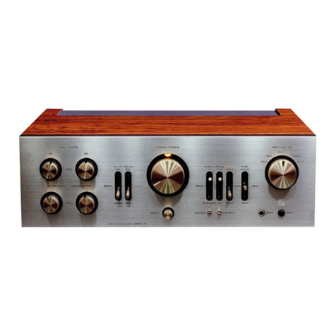
Luxman
Luxman L116A User manual

Luxman
Luxman EQ-500 User manual