LUXX LIGHTING LUX-200-277-80 User manual

200w LED BAR
LUX-200-277-80
USER MANUAL

BEFORE YOU PROCEED
Make sure to register your products by visiting www.luxxlighting.com/warranty or by scanning the QR code. Registering for warranty ensures
faster service on any future unseen circumstances and keeps you connected on updates.
Thank you for being a part of the Luxx Lighting family. This manual will guide you through the usage and installation process of the Luxx
Lighting 200w LED Bar. Please read and understand this manual in its entirety before using the product. Only use this product as specied
within the manual.
PRODUCT DESCRIPTION
The 200w LED Bar is a breakthrough product for indoor and greenhouse cultivation. The modular design and form factor enables getting just the right amount of light
distributed properly across the canopy. Use between 1 to 5 200w LED Bars to get your targeted PPFD depending on your footprint. With the use of our Bar Bracket,
each 200w LED Bar can be deployed in an array to provide the targeted light levels. At just 200w, the low power level allows for building up the PPFD at the canopy
in 200w increments so you don’t have to pay for more light than you need, while the bars are dimmable to enable getting just the right amount of light. Working
together the 200w LED Bars provide high intensity, uniform light to the canopy. The modular design of the 200w LED Bar and Bar Bracket allows for specic spacing
and placement over the canopy and quick and easy installation. The slim and linear form factor of the 200w LED Bar also enables their use in greenhouses. Single
or pairs of 200w LED Bars can be deployed along greenhouse structural elements to minimize cast shadows across your canopy during the day while providing
maximum ecacy and light supplementation.

1000w800w400w 600w200w
200W LED BAR CONFIGURATIONS
80R SPECTRUM
The 80R spectrum provides a full spectrum with maximum red photon content. The red content is eciently
generated by state of the art LEDs and is the most eective portion of the spectrum for plant growth and yield.
The blue-green balance supports healthy plant morphology and enables an improved working environment and
improved visual inspection for growers. This spectrum has been tested extensively for full scale indoor plant
production and has consistently resulted in the fastest growth of healthy, high-yield plants.
WARNING
The 80R spectrum was designed specically for use in the vegetative phase of growth. Do not use this spectrum
for owering. While this spectrum has demonstrated higher yield and higher THC for ower grown using it, there
will be some bleaching on the tips during the owering phase.

PRODUCT SPECIFICATIONS
Technical Specs
Input Power 200W
Min Power Factor >0.95
Rated Mains Voltage 200V - 277V
Voltage Range 200V - 305V
Mains Frequency 50/60Hz
THD <10%
Thermal Management Passive
Dimming 40% to 100% - EXT/OFF
If using our NX-1, only dimmable
down to 50%.
Power Cord Selection Required:
10’ 240v or 10’ 277v power cord
options available.
Size & Weight
Length 1240mm 49"
Width 60mm 2.36"
Height 72mm 2.83"
Weight 3.26kg 7.20 lbs
Input Voltage Input Current
208V 0.96A
220V 0.90A
240V 0.83A
277V 0.72A
CONTENTS
• Eyelet Bolts (2 PCS) • Eyelet Bolt Nuts (2 PCS) • Instruction Manual• 1/4" Hex Head Bolts (2 PCS) • Unistrut Wire Hangers (2 PCS)• Wing Nuts (2 PCS) • Washers (2 PCS)

DAISY CHAINING THE 200W LED BAR
The chart shows the maximum amount of 200w LED Bars that can be daisy chained together based on the voltage
of your electrical system.
Voltage Daisy Chain Quantity
208V 15
220V 16
240V 17
277V 20
PPFD FOOTPRINTS
2 BAR | 400W | AVG PPFD: 363
5’ FOOTPRINT | TESTED AT 24”
Distance From Canopy: 24” |5x5 Footprint
134 299 138
228 397 237
355 469 360
447 508 454
476 492 480
213 288 364 430 464 480 464 422 367 282 204
473 488 470
449 499 441
356 469 348
241 398 228
147 302 132
Average PPFD = 363
Luxx 200w LED Bar 80R
Configuration: 2 Bar, 400w | 80% Red
Distance From Canopy: 24” |4x4 Footprint
83 131 86
144 195 156
252 295 263
364 377 367
221 293 358 399 409 401 371 311 237
354 374 368
247 278 252
141 190 147
76 126 80
Average PPFD = 252
Luxx 200w LED Bar 80R
Configuration: 1 Bar, 200w | 80% Red
3 BAR | 600W | AVG PPFD: 537
5’ FOOTPRINT | TESTED AT 24”
Distance From Canopy: 24” |5x5 Footprint
216 495 227
344 586 353
504 666 514
618 704 622
713 735 711
321 439 567 660 714 738 724 651 570 438 314
702 729 707
625 697 621
494 647 503
344 575 346
212 477 200
Average PPFD = 537
Luxx 200w LED Bar 80R
Configuration: 3 Bar, 600w | 80% Red
4 BAR | 800W | AVG PPFD: 725
5’ FOOTPRINT | TESTED AT 24”
Distance From Canopy: 24” | 5x5 Footprint
284 650 291
464 776 453
668 883 661
860 964 855
967 994 966
434 594 759 907 974 1005 972 891 756 578 406
970 985 958
860 952 848
683 885 657
470 779 451
301 654 282
Average PPFD = 725
Luxx 200w LED Bar 80R
Configuration: 4 Bar, 800w | 80% Red
1 BAR | 200W | AVG PPFD: 252
4’ FOOTPRINT | TESTED AT 24”

INSTALLATION
WARNING! READ THE FOLLOWING INSTRUCTIONS CAREFULLY BEFORE USING OR WORKING WITH THE 200W LED BAR.
•The 200w LED Bar contains a glass lens over the LEDs. Please handle with care.
• Always gently place the 200w LED Bar on a clean, soft surface to avoid damaging the glass.
• In order to mount your 200w LED Bar properly, start by identifying a suitable support structure that you can mount your 200w LED Bar to.
• Common support structures include pallet racks, trusses, structural channels, Unistrut, and rolling tables.
• The user is responsible for correct and safe installation and usage.
• Please have two or more experienced, certied service personnel mount and install this device, in accordance with the applicable local laws and regulations.
•Best practices are to have a licensed electrician install your 200w LED Bar.
• Ensure the existing electrical system can support the voltage and current requirements of the 200w LED Bar.
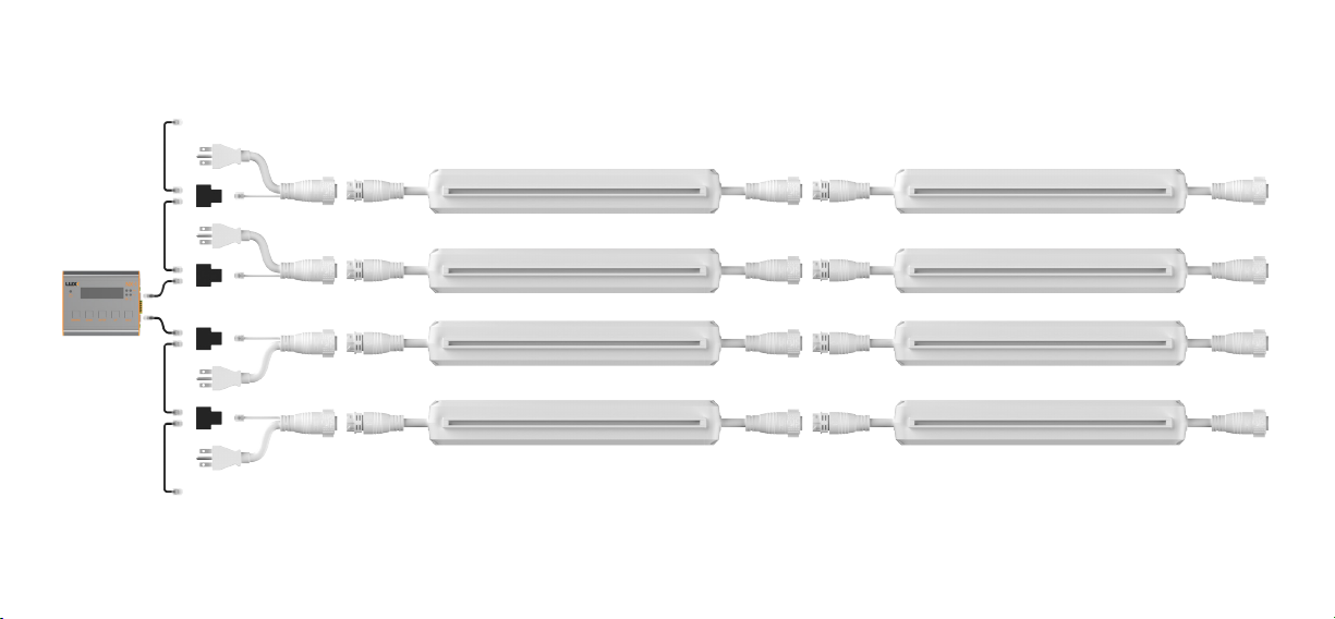
• When daisy chaining the 200w LED Bars together, make sure that you’re not attempting to connect more than the maximum amount of 200w LED Bars based on
the voltage that your power cable and electrical system are rated for. Read the product specications to see the maximum amount of 200w LED Bars that can be daisy
chained together.
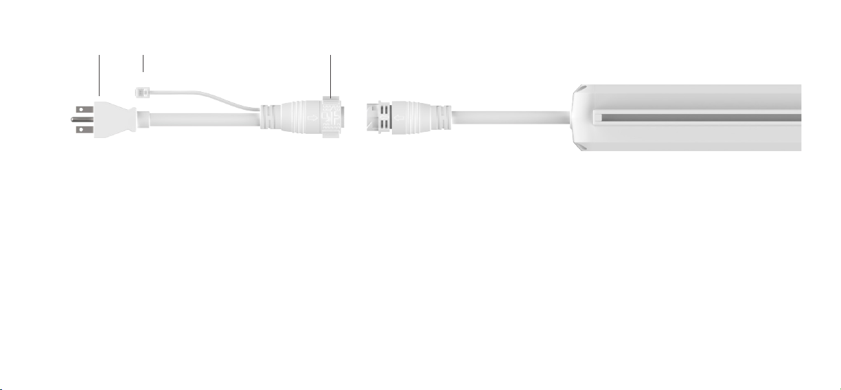
200W LED BAR POWER CORD
The power cord for the 200w LED Bar integrates both power and 0-10v dimming signal through fully shielded cabling and a single 5-pin IP67 rated connector. The 200w
LED Bar features input and output cables that allow you to supply power and dimming signal by daisy chaining 15x to 20x 200w LED Bars together based on the voltage
of your electrical system. If you're using our NX-1 Controller, you can control up to 100x 200w LED Bars per channel with the use of RJ14 splitters and interconnect
cables (1 of each included with each power cord).

RJ14 Twist LockPower
CONNECTING UP TO 200x 200W LED BARS
How to connect the 200w LED Bar to our NX-1 Controller:
• Slide the switch on the bottom of the 200w LED Bar to the EXT/OFF position in order to receive a signal from the NX-1 Controller.
• Plug the RJ14 connector coming out of the power cord into the single connector end of a RJ14 splitter.
• Plug the RJ9 end of a controller cable (included with the NX-1 Controller) into the RJ9 main port of the NX-1 Controller.
• If a two room setup is used or if more than 100x 200w LED Bars have to be connected, plug a second controller cable in the RJ9 aux port.
• Plug the RJ14 end of the controller cable(s) into the dual connector end of the RJ14 splitter.
• Plug either end of an interconnect cable into the other dual connector end of the RJ14 splitter.
• Plug the other end of the interconnect cable into the dual connector end of the following RJ14 splitter.
• Repeat this process to connect up to 100x 200w LED Bars on the RJ9 aux port.


Bar BracketWire hangers to Unistrut Direct mounting to Unistrut Rope Ratchets
MOUNTING METHODS
There are four ways to mount the 200w LED Bar system:
HOW TO DAISY CHAIN THE 200W LED BAR
There are multiple ways to congure our 200w LED Bar and Bar Bracket when daisy chaining them together.

DIRECT MOUNTING TO UNISTRUT
1. Remove the cap on the end of the slot. Insert
two 1/4" hex bolts that are at least 2.25" long (not
included) into the slot.
2. Space the hex bolts towards the end of the LED.
Lift the 200w LED Bar up until the bolts go through
the slots on top of the Unistrut.
3. Install a fender washer and 1/4" wing nut on the
hex bolt to secure the 200w LED Bar to the Unistrut.
WIRE HANGERS TO UNISTRUT
1. Place the wire hangers over your Unistrut. Lift the 200w LED Bar into the Unistrut. 2. Put the ends of the wire hanger into the holes on the bottom of the 200w LED Bar.

ROPE RATCHETS
1. Remove the cap on the end of the slot. Screw the eyelet bolt into the hex nut
and insert it into the slot.
2. Position each eyelet bolt towards the ends of the 200w LED Bar. Tighten
down the eyelet bolt to secure it in place.
BAR BRACKET
The Bar Bracket (not included with 200w LED BAR) was designed to congure 2, 3, 4 or 5 200w LED Bars together to create a complete modular system capable of
covering both a 4' wide and 5' wide footprint. The Bar Bracket features 17 notches that are used to properly space 200w LED Bars together to create a 400w, 600w,
800w or 1000w system. The multiple notches along the bottom of the bracket are positioned to achieve optimal light distribution for each conguration that you can
achieve with the 200w LED Bar.

MOUNTING THE 200W LED BAR TO THE BAR BRACKET
1. Remove the cap on the end of the slot. Insert the two included 1/4" hex bolts into
the slots.
2. Lift the 200w LED Bar and hex bolts up through the appropriate notch and
hole in the Bar Bracket. Tighten down the wing nut to secure it in place.
BAR BRACKET INSTALLATION TIPS
•Determine how many power cords you will need based on how many 200w LED Bars you can daisy chain together. This is determined by the power cable you
select that is rated for your electrical systems voltage.
•Plan out how you want to daisy chain your 200w LED Bars in your room to determine where the power cables need to go.
•You can daisy chain each 200w LED Bar left to right or you can go up and down along your room.
•Use the Unistrut cleat included with the Bar Bracket to give you clearance around Unistrut splice plates and hardware. The Unistrut cleat also helps keep each Bar
Bracket perpendicular to the Unistrut.
•Zip tie extra cable to the Bar Bracket after installation is complete.

MOUNTING THE BAR BRACKET TO UNISTRUT
1. If you're running a 600w or 1000w system, mount the Bar Bracket through the
middle 200w LED Bar.
2. If you're running a 400w or 800w system, the Bar Bracket is mounted to
Unistrut on its own without a middle 200w LED Bar.

2. Make sure the hex bolt is seated between
the two small vertical ribs in the Bar Bracket.
3. Insert the Unistrut cleat over the hex bolt.
5. Make sure the Unistrut cleat is seated properly
between the gap in the bottom of the Unistrut.
4. Lift the Bar Bracket, hex bolt and Unistrut cleat
up through the slot in the Unistrut.
MOUNTING A 400W OR 800W SYSTEM
4. Start by inserting the 1/4" x 3.5" hex bolt
through the bottom of the Bar Bracket.
6. Place the fender washer and wing nut over the
hex bolt and tighten them down.

4. Make sure the Unistrut cleat is seated properly
between the gap in the bottom of the Unistrut.
5. Place the fender washer and wing nut over the
hex bolt and tighten them down.
2. Insert the Unistrut cleat over the hex bolt. 3. Lift the 200w LED Bar, Bar Bracket, hex bolt and
Unistrut cleat up through the slot in the Unistrut.
MOUNTING A 600W OR 1000W SYSTEM
1. Start by inserting the 1/4" x 3.5" hex bolt into the
slot of the middle 200w LED Bar.

MOUNTING THE BAR BRACKET WITH LANCE HANGERS
• Install 4 eyelets, one on each end of each Bar Bracket.
• Clip the carabiners onto the two opposing eyelets on each Bar Bracket.
• Allow an additional 8” from the top of Bar Bracket for the height of lance hangers.
Install eyelet bolt here Install eyelet bolt here

5 YEAR WARRANTY
• Luxx Lighting warranties the mechanical and electronic
components of the 200w LED Bar and guarantees the materials
and workmanship free of defects, if used under normal
operating conditions within a period of ve (5)years from the
purchase date.
• All returns and claims must be presented with the original
proof of purchase.
• If you nd that there are any defects with this product
that relate to either the workmanship or the materials but are
not due to improper use or user error, Luxx Lighting shall, at
its discretion, either replace or repair the product using the
appropriate new or reconditioned parts.
• In the case that Luxx Lighting decides to replace the entire
product, the date of the limited warranty shall apply to the
replacement from the date of the purchase of the initial product
for ve (5) years.
• We’ve performed a lifetime analysis test of our LED and
guarantee that at 54,000 hours they will still produce 90%
output.
• All returns must be registered at www.luxxlighting.com/rma
ENVIRONMENT
• The 200w LED Bar has an IP66 rating and is designed to be used in a high-humidity environment.
• Optimal ambient air temperature for this LED xture is between 15°C-60° F / 26°C-80° F.
• The 200w LED Bar is NOT intended to be used outdoors and should not be directly exposed to water.
MAINTENANCE
• Clean with warm water and a microber cloth.
• Do not use detergents, abrasives or other aggressive substances.
• Please regularly check for dust or dirt buildup. Clean if necessary. Contamination may cause
overheating and decreased performance.
• Regularly check the cable connections to ensure it is undamaged.
STORAGE AND DISPOSAL
• This xture is to be stored at an ambient temperature of to 15°C-60° F / 26°C-80° F in a dry and
clean environment.
• This product must not be disposed of as standard waste. It is to be collected or brought to a
recycling center for proper disposal and environmental treatment.

Luxx 200 LED Bar
IMPORTANT SAFETY INFORMATION. READ THIS INFORMATION AND FULL USER
MANUAL CAREFULLY PRIOR TO INSTALLING THIS PRODUCT.
Installation of the horticultural lighting structures described in this manual shall be performed by qualied personnel and are intended for
installation subject to approval by the authority having jurisdiction. Follow all installation, operation and maintenance instructions in the
complete user manual provided with this product.
Please note that failure to follow directions related to installation, use and/or maintenance may result in serious injury, death, or
property damage and will void the warranty, and the purchaser will be responsible for any and all repairs and/or damages incurred.
CAUTION - PROPRIETARY WIRING SYSTEM. Use Hawthorne/Luxx cord set model HGC906341 or HGC906342 only for connection
from the luminaire power inlet to a standard junction box for power connection.
ATTENTION - SYSTÈME DE C BLAGE PROPRIÉTAIRE. Utilisez le jeu de cordons Hawthorne modèle HGC906341 ou HGC906342
uniquement pour la connexion de l’entrée d’alimentation du luminaire à une boîte de jonction standard pour la connexion électrique.
MAXIMUM DISTANCE BETWEEN UNITS TO BE INTERCONNECTED: 4 M
DISTANCE MAXIMALE ENTRE LES UNITÉS À INTERCONNECTER: 4 M
MAXIMUM UNITS TO BE INTERCONNECTED: See manual.
MAXIMUM D’UNITÉS À INTERCONNECTER: Voir le manuel.
Install with a minimum 15 cm distance between adjacent lighting equipment and between the lighting equipment and
combustible materials such as walls, ceilings, movable partitions, and the like; and between lighting equipment and other heat
generating equipment.
Environment
The product is intended to be used in greenhouses and climate rooms. NOT FOR INTRACANOPY USE. The product can be used
in wet environments. The product may not be used outdoors. This luminaire is suitable for operation in an ambient temperature
not exceeding 40°C. This should be the maximum sustained temperature of the installed environment (ambient temperature)
that will ensure safe operation of the lighting equipment. To prevent sustained temperatures above a 40°C ambient a mechanical
ventilation or cooling system is required to maintain the temperature within the growing space at or below 40°C when the
luminaire is in operation.
Be sure cord sets or wiring harnesses:
1) Are not concealed or extended through a wall, oor, ceiling, or other parts of the building structure;
2) Are not located above a suspended ceiling or dropped ceiling;
3) Are not permanently axed to the building structure;
4) Are routed so that they are not subject to strain and are protected from physical damage;
5) Are visible over their entire length; and
6) Are used within their rated ampacity as determined for the maximum temperature of the installed environment specied in the
instructions.
Connecting the LED xture to the mains
Warning! Make sure mains power is switched o.
Warning! Ensure the cord is not coiled and does not touch any hot surfaces.
Warning! Connect the cables according to local rules, safety regulations and electrical code.
Warning! Ensure external switching gear can cope with the inrush current of the LED xture (see section 3.2). Always use a
double-pole contactor suitable for switching a capacitive load. Never use household timers to switch the LED xture!
Avertissement! Assurez-vous d’éteindre l’alimentation au conducteur principal.
Avertissement! Assurez-vous que le cordon n’est pas enroulé et qu’il n’est pas en contact avec des surfaces chaudes.
Avertissement! Branchez les câbles conformément aux règlements locaux, aux règlements de sécurité et au code de
l’électricité
Avertissement! Assurez-vous que l’équipement de commutation externe peut soutenir l’appel de courant du dispositif à
DEL (voir section 3.2). Toujours utiliser un contacteur bipolaire convenant à la commutation d’une charge capacitive. Ne jamais
utiliser une minuterie maison pour commuter le dispositif à DEL!

Daisy Chaining
If daisy-chaining mains power for the Luxx 200W LED Pro, then it is recommended to use a suitable surge protector. Consult an
electrician for the appropriate ratings and installation of the surge protectors.
Connect the appropriate cord set to the power inlet cord connector of the luminaire.
For 208-240Vac the cord set will be provided with a NEMA Type plug. Plug the power cord into the mains. Switch on mains power.
For 277Vac the cord set is provided with a 15 amp plug.
This device complies with part 15 of the FCC Rules. Operation is subject to the following two conditions: (1) This device may
not cause harmful interference, and (2) this device must accept any interference received, including interference that may cause
undesired operation.
CAUTION – Changes or modications not expressly approved by the party responsible for compliance could void the user’s
authority to operate the equipment.
NOTE: This equipment has been tested and found to comply with the limits for a Class A digital device, pursuant to part 15 of
the FCC Rules. These limits are designed to provide reasonable protection against harmful interference when the equipment
is operated in a commercial environment. This equipment generates, uses, and can radiate radio frequency energy and, if
not installed and used in accordance with the instruction manual, may cause harmful interference to radio communications.
Operation of this equipment in a residential area is likely to cause harmful interference in which case the user will be required to
correct the interference at his own expense
FOR COMPLETE INFORMATION REGARDING THIS PRODUCT, PLEASE REFER TO THE USER MANUAL.
Table of contents
Other LUXX LIGHTING Lantern manuals
Popular Lantern manuals by other brands

Acuity Brands
Acuity Brands HOLOPHANE PRISMASHIELD & EMERGENCY installation instructions

Hilti
Hilti NURON SL 2-22 manual

Primus
Primus MIMER LANTERN DUO Instructions for use

Lighting Technologies
Lighting Technologies INSEL LB/S LED Series manual

COGEX
COGEX SolarLine 313196 instruction manual

Nature Power
Nature Power 21060 user manual