LYNXTechnik C MX 5710 User manual

LYNXTechnik AG
Broadcast Television Equipment
© 2011 - 2015 LYNX Technik AG all rights reserved
®
Reference Manual
C MX 5710
HD/SD Analog Video to SDI Converter with Frame Synchronizer,
Analog Audio Inputs and AES Ports
Revision 1.0 –July 2015
This Manual Supports Device Revisions:
C MX 5710 Firmware Revision
688
Control System GUI Release
8.4.0
Information in this document is subject to change without notice. No part of this document may be reproduced or
transmitted in any form or by any means, electronic or mechanical for any purpose, without express written permission of
LYNX Technik AG.
LYNX Technik AG may have patents, patent applications, trademarks, copyrights or other intellectual property rights
covering the subject matter in this document. Except as expressly written by LYNX Technik AG, the furnishing of this
document does not give you any license to patents, trademarks, copyrights or other intellectual property of LYNX Technik
AG or any of its affiliates.
LYNX Technik AG
Brunnenweg 3
D 64331 Weiterstadt
Germany
www.lynx-technik.com

C MX 5710 Reference Manual. Rev 1.0
Page 2 of 36
Contents
Contents ...............................................................................................................2
Warranty ...............................................................................................................4
Regulatory information ........................................................................................5
Europe......................................................................................................................................... 5
Declaration of Conformity ....................................................................................................... 5
USA............................................................................................................................................. 5
FCC 47 Part 15....................................................................................................................... 5
Getting Started.....................................................................................................6
Packaging.................................................................................................................................... 6
ESD Warning............................................................................................................................... 6
Preventing ESD Damage........................................................................................................ 6
Caution.................................................................................................................................... 6
Product Description .............................................................................................7
Functional Diagram ..................................................................................................................... 8
Connection Panel and Module Layout........................................................................................ 9
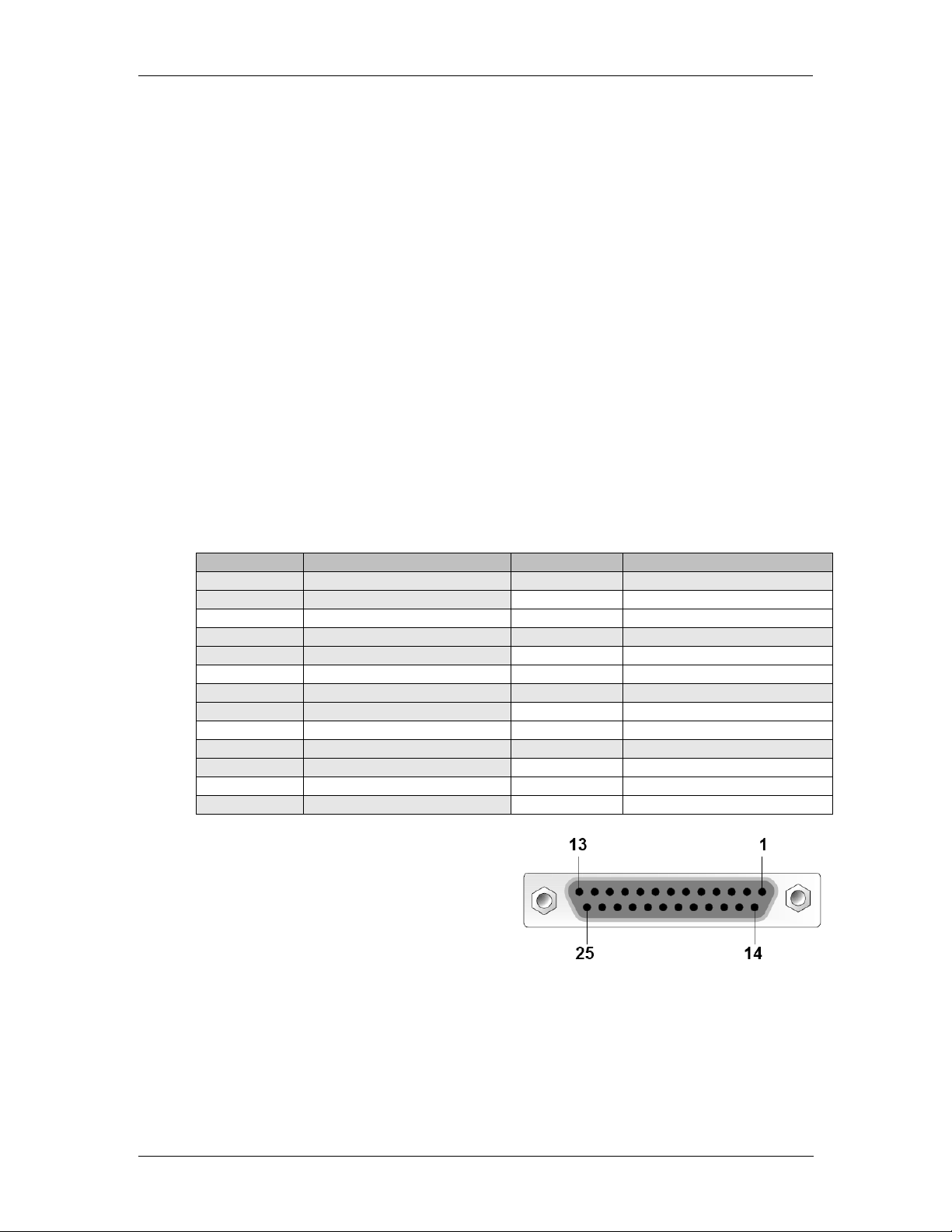
Connections .............................................................................................................................. 10
Video..................................................................................................................................... 10
Sub-D 25 Pinout.................................................................................................................... 10
Video Processing ...................................................................................................................... 11
A/D Converter Functions....................................................................................................... 11
Proc Amp Functions.............................................................................................................. 11
Aperture Correction............................................................................................................... 11
Test Pattern .......................................................................................................................... 11
Programmable Video Output Delay...................................................................................... 11
Audio Processing ...................................................................................................................... 12
Analog Audio Inputs.............................................................................................................. 12
Digital Audio I/O.................................................................................................................... 12
Processing ............................................................................................................................ 12
Frame Synchronization ............................................................................................................. 12
Installation .........................................................................................................13
Local Control and LEDs......................................................................................14
Switch Settings........................................................................................................................ 14
Alarm/LED Status Indicators..................................................................................................... 15
LED: Video Status................................................................................................................. 15
LED: Audio Status................................................................................................................. 15
LED: Local / Remote............................................................................................................. 15
Alarm LED............................................................................................................................. 15
Power LEDs.......................................................................................................................... 15
Control System GUI............................................................................................16
Overview ................................................................................................................................... 17
flexGUI path highlighting and signal patching ...................................................................... 17
A/D Converter Control........................................................................................................... 18
Frame Synchronizer.............................................................................................................. 18

C MX 5710 Reference Manual. Rev 1.0
Page 3 of 36
Reference Source Selection................................................................................................. 19
Video Processing ...................................................................................................................... 19
Aperture Correction............................................................................................................... 19
Clip CR/Cb Headroom.......................................................................................................... 20
Output if no input................................................................................................................... 20
Test Pattern Pre-select......................................................................................................... 20
Test Pattern Standard........................................................................................................... 20
Test Pattern Enable.............................................................................................................. 20
Video Adjustments................................................................................................................ 21
Audio Infastructure .................................................................................................................... 21
AES Audio Content Detection............................................................................................... 21
Sample Rate Conversion...................................................................................................... 21
AES Port Setup..................................................................................................................... 22
Analog Audio Inputs.............................................................................................................. 22
Audio Processing.................................................................................................................. 22
Audio Crossbars ................................................................................................................... 23
Embedder ............................................................................................................................. 25
Meta Data.................................................................................................................................. 26
Time Code ............................................................................................................................ 26
Format Description................................................................................................................ 27
Timing and Delays..................................................................................................................... 28
Video Timing Adjustments.................................................................................................... 28
Audio Timing Adjustments.................................................................................................... 28
Timing Tab............................................................................................................................ 29
Device Event Tab ...............................................................................................29
Parameters .........................................................................................................30
Parameters control everything .................................................................................................. 31
General GUI functions........................................................................................32
Device Properties.................................................................................................................. 32
Locate ................................................................................................................................... 32
New Control Window ............................................................................................................ 32
Rename................................................................................................................................. 33
Save Settings Now................................................................................................................ 33
Lock....................................................................................................................................... 33
Reset Factory Defaults ......................................................................................................... 33
Settings Management........................................................................................................... 33
Specifications ....................................................................................................34
Service ...............................................................................................................36
Parts List ................................................................................................................................... 36
Technical Support ..................................................................................................................... 36
Contact Information ...........................................................................................36

C MX 5710 Reference Manual. Rev 1.0
Page 4 of 36
Warranty
LYNX Technik AG warrants that the product will be free from defects in materials
and workmanship for a period of two (3) years from the date of shipment. If this
product proves defective during the warranty period, LYNX Technik AG at its
option will either repair the defective product without charge for parts and labor,
or will provide a replacement in exchange for the defective product.
In order to obtain service under this warranty, customer must notify LYNX
Technik of the defect before expiration of the warranty period and make suitable
arrangements for the performance of service. Customer shall be responsible for
packaging and shipping the defective product to the service center designated by
LYNX Technik, with shipping charges prepaid. LYNX Technik shall pay for the
return of the product to the customer if the shipment is within the country which
the LYNX Technik service center is located. Customer shall be responsible for
payment of all shipping charges, duties, taxes and any other charges for products
returned to any other locations.
This warranty shall not apply to any defect, failure, or damage caused by
improper use or improper or inadequate maintenance and care. LYNX Technik
shall not be obligated to furnish service under this warranty a) to repair damage
resulting from attempts by personnel other than LYNX Technik representatives to
install, repair or service the product; b) to repair damage resulting from improper
use or connection to incompatible equipment; c) to repair any damage or
malfunction caused by the use of non LYNX Technik supplies; or d) to service a
product which has been modified or integrated with other products when the
effect of such modification or integration increases the time or difficulty servicing
the product.
THIS WARRANTY IS GIVEN BY LYNX TECHNIK WITH RESPECT TO THIS
PRODUCT IN LIEU OF ANY OTHER WARRANTIES, EXPRESS OR IMPLIED.
LYNX TECHNIK AND ITS VENDORS DISCLAIM ANY IMPLIED WARRANTIES
OF MERCHANTABILITY OR FITNESS FOR A PARTICULAR PURPOSE.
LYNX TECHNIK`S RESPONISIBILITY TO REPAIR AND REPLACE
DEFECTIVE PRODUCTS IS THE SOLE AND EXCLUSIVE REMEDY
PROVIDED TO THE CUSTOMER FOR BREACH OF THIS WARRANTY. LYNX
TECHNIK AND ITS VENDORS WILL NOT BE LIABLE FOR ANY INDIRECT,
SPECIAL, INCIDENTIAL, OR CONSEQUENTIAL DAMAGES IRRESPECTIVE
OF WHETHER LYNX TECHNIK OR THE VENDOR HAS ADVANCE NOTICE
OF THE POSSIBILITY OF SUCH DAMAGES.

C MX 5710 Reference Manual. Rev 1.0
Page 5 of 36
Regulatory information
Europe
Declaration of Conformity
USA
FCC 47 Part 15
This device complies with part 15 of the FCC Rules. Operation is subject to the following
two conditions: (1) This device may not cause harmful interference, and (2) this device
must accept any interference received, including interference that may cause undesired
operation.
Note: This equipment has been tested and found to comply with the limits for a Class A
digital device, pursuant to the part 15 of the FCC Rules. These limits are designed to
provide reasonable protection against harmful interference when the equipment is
operated in a commercial environment. This equipment generates, uses, and can radiate
radio frequency energy and, if not installed and used in accordance with the instruction
manual, may cause harmful interference to radio communications. Operation of this
equipment in a residential area is likely to cause harmful interference in which case the
user will be required to correct the interference at their own expense.
We LYNX Technik AG
Brunnenweg 3
D-64331 Weiterstadt
Germany
Declare under our sole responsibility that the product
TYPE: C MX 5710
To which this declaration relates is in conformity with the following
standards (environments E1-E3):
EN 55103-1 /1996
EN 55103-2 /1996
EN 60950-1 /2006
Following the provisions of 89/336/EEC and 73/23/EEC directives.
Winfried Deckelmann
Weiterstadt, July 2015
Place and date of issue Legal Signature

C MX 5710 Reference Manual. Rev 1.0
Page 6 of 36
Getting Started
Most CardModules are installed into the rack frames and system tested in the
factory. If this is an upgrade part or service exchange item then the module is
supplied in a padded cardboard carton which includes the CardModule, rear
connection plate and mounting screws.
Packaging
The shipping carton and packaging materials provide protection for the module
during transit. Please retain the shipping cartons in case subsequent shipping of
the product becomes necessary. Do not remove the module from its protective
static bag unless observing adequate ESD precautions. Please see below.
ESD Warning
This product is static sensitive. Please use caution and use preventative
measures to prevent static discharge or damage could result to module.
Preventing ESD Damage
Electrostatic discharge (ESD) damage occurs when electronic assemblies or the
components are improperly handled and can result in complete or intermittent
failure.
Do not handle the module unless using an ESD-preventative wrist strap and
ensure that it makes good skin contact. Connect the strap to any solid grounding
source such as any exposed metal on the rack chassis or any other unpainted
metal surface.
Caution
Periodically check the resistance value of the antistatic strap. The measurement
should be between 1 and 10 Megohms.

C MX 5710 Reference Manual. Rev 1.0
Page 7 of 36
Product Description
The C MX 5710 provides high quality composite / component SDTV and HDTV
video A/D conversion, audio A/D conversion plus frame synchronisation and
audio embedding functionality in a single, versatile self-contained module.
The video conversion capabilities include high quality 12 bit A/D conversion with
54 MHz sampling. 5-line adaptive comb filter decoder plus a choice of CVBS /
RGB / YUV / YC SDTV analog video inputs or RGB / YUV HDTV analog inputs.
The module provides the quality and versatility for use in the most demanding
applications.
Audio capability includes support for 2 sets of analog stereo pair inputs 24 bit A/D
conversion and selectable full scale range.
In addition 2 x digital AES audio ports are provided which can be individually
configured as inputs or outputs.
Integrated audio processing includes adjustable gain, phase, invert and a sum
function. Audio channels can also be shuffled using the integrated audio
crossbar. Automatic timing compensation is provided with a user adjustable
offset. A fully featured audio embedder includes a 8 x 16 audio crossbar for audio
assignments.
An adjustable video delay of up to 62 frames adjustable in frame, lines and pixels
increments is provided for system timing.
Full remote control is provided via the APPolo control system.

C MX 5710 Reference Manual. Rev 1.0
Page 8 of 36
Functional Diagram
Figure 1: Functional Diagram

C MX 5710 Reference Manual. Rev 1.0
Page 9 of 36
Connection Panel and Module Layout
Figure 2: Connections
Figure 4: Board
Figure 3: Board Edge

C MX 5710 Reference Manual. Rev 1.0
Page 10 of 36
Connections
Video
The C MX 5710 uses standard 75 Ohm BNC connectors for the analog video and
reference input connections as well as for the SDI output. We recommend the
use of high quality video cable for digital video connections to reduce the risk of
errors due to excessive cable attenuation. Max output cable lengths the module
will support are shown below.
SDTV = 250m Belden 8281 (270Mbits/s)
HDTV = 140m Belden 1694A (1.4Gbits/s)
NOTE:Due to the compact design of the connection plate it will be necessary to
use a connection tool to secure the BNC video connectors.
Sub-D 25 Pinout
The module has a Sub-D 25 connector for the analog audio, AES audio and GPI
in and outputs. The pinout is as shown in Table 1: Sub-D 25 Pinout.
Pin Number
Connection
Pin Number
Connection
1
Analog Audio In 1L +
14
Analog Audio In 1L -
2
Analog Audio In 1L GND
15
Analog Audio In 1R +
3
Analog Audio In 1R -
16
Analog Audio In 1R GND
4
Analog Audio In 2L +
17
Analog Audio In 2L -
5
Analog Audio In 2L GND
18
Analog Audio In 2R +
6
Analog Audio In 2R -
19
Analog Audio In 2R GND
7
AES Port 1 +
20
AES Port 1 -
8
AES Port 1 GND
21
AES Port 2 +
9
AES Port 2 -
22
AES Port 2 GND
10
GPI 1
23
n.c.
11
GPI 1 GND
24
GPI 2
12
n.c.
25
GPI 2 GND
13
n.c.
Table 1: Sub-D 25 Pinout
It is recommended to use high
quality screened (twisted pair) cable
for the balanced audio connections.
LYNX Technik provides optional
audio breakout cables which will
bring out all signals to in line XLR
connectors. Model numbers RAC M/F
25-4/4, RAC M 25-8 or RAC M 25-8.
Figure 5: SubD25 Audio connector
(looking into connector from back of
module)

C MX 5710 Reference Manual. Rev 1.0
Page 11 of 36
Video Processing
A/D Converter Functions
The A/D converter provides a high quality 12 bit A/D conversion with 54 MHz
sampling. Adjustable Chroma, Pedestal and Hue are available with the APPolo
control software.
A wide range of comb filter settings as well as Luminance, Chrominance, Cb and
Cr Gain and Cb, Cr Offset settings are provided.
Proc Amp Functions
The output has an associated video processing amp which provides user
adjustable Gain, Saturation, Black Level and Hue using GUI sliders.
Aperture Correction
An adjustable horizontal aperture corrector is available for the output. This can be
used to add (or remove) image sharpness as required.
Test Pattern
The output has an integrated test pattern generator which provides a wide
selection of test patterns.
The selected test pattern can also be setup to turn on automatically if no input
signal is detected.
Programmable Video Output Delay
The SDI output has a programmable video output delay which can be set
between 0 and 62 frames (max). The adjustment is available in pixel, line and full
frame increments.
This adjustment will delay the SDI video output relative to the connected
reference by the delay setting specified. (+ fixed delay)
NOTE: The Synchronizer has fixed frame delays depending on the signal path and
selected function. The 0 > 62 frame user adjustment is additional delay relative to
the fixed delays.

C MX 5710 Reference Manual. Rev 1.0
Page 12 of 36
Audio Processing
Analog Audio Inputs
The full scale level of the analog audio inputs can be adjusted in addition a
manual delay is available.
Digital Audio I/O
The AES ports can individually be configured to either be an input or output
When setup as an input the type of audio (PCM, Dolby E or Audio Data) is
detected by the module automatically.
The module provides manual delay stages on the input and output of the AES
signals.
Processing
Four AES channels (8 audio channels) of audio processing are available with
gain, mute and phase invert functions. In addition to this, each channel has a
sine test signal generator as well as over level and silence detection.
Frame Synchronization
The frame synchronizer will output a stable SDI in sync to the connected
reference signal. The module will accept black & burst reference as well as bi-
level and tri-level sync signals.
Adjusting the output timing of the module will adjust the SDI output relative to the
reference signal.

C MX 5710 Reference Manual. Rev 1.0
Page 13 of 36
Installation
If this module was supplied as part of a system it is already installed in the rack
enclosure. If the module was supplied as a field upgrade please follow the
installation procedure below.
NOTE Observe static precautions when handling card.
Please see ESD warnings on Page 7.
This module has a single width rear connection panel. Up to ten C MX 5710
modules can be accommodated in a single Series 5000 2RU rack frame.
Each Card Module is supplied with a rear connection panel and mounting
screws. Please follow the procedure below for the installation of the card module
into the Series 5000 Card Frame.
We recommend you power the rack down before installing any additional
modules into an existing card frame.
1. Select a free slot space in the card frame where the CardModule will be
located.
2. Remove the blank connection panels from the rear of the rack (if fitted)
3. Install the rear connection panel using the screws supplied. Do not tighten
the screws fully
4. Slide the card module into the card frame and carefully check the
CardModule connects to the rear connection plate. The card should fit
easily and should not require excessive force to insert - if you feel any
resistance, there could be something wrong with the rear connection
panel location. Do not try and force the connection this may damage the
connectors. Remove the rear connection panel and check alignment with
the CardModule.
5. Insert and remove the CardModule a few times to ensure correct
alignment and then tighten the two screws to secure the rear connection
plate.
6. Power up the rack and check the module LED’s. Check the module is
automatically logged into the control system device tree. (It may take a
few seconds for the control system to “discover” the new module)
NOTE:The use of the optional control system is mandatory for the control and
setup of this module. If you do not have the control system, then please
contact your LYNX representative for details on how to upgrade your
installation with the LYNX control system.

C MX 5710 Reference Manual. Rev 1.0
Page 14 of 36
Local Control and LEDs
The C MX 5710 module has an integrated micro-controller, which enables the
module to be configured and controlled locally using the dip switches at the edge
of the board.
Advanced settings are available via the APPolo control software.
Once set, all settings are automatically saved in non-volatile internal memory.
(Flash RAM) The module will always recall the last used settings.
Switch Settings
Below the switch settings for the 8-position dip-switch are defined.
Switch
Setting
Function
1
ON
Enable Local Adjustment
OFF
Disable Local Adjustment
2
ON
Audio Embedder for Group 1 active
OFF
No Embedding for Audio Embedder Group 1
3
ON
Audio Embedder for Group 2 active
OFF
No Embedding for Audio Embedder Group 2
4
ON
Audio Embedder for Group 3 active
OFF
No Embedding for Audio Embedder Group 3
5
ON
Audio Embedder for Group 4 active
OFF
No Embedding for Audio Embedder Group 4
6
ON
Ref Source Board
OFF
Ref Source Rack
7
ON
No Function
OFF
No Function
8
ON
Output if no Input “Testpattern”
OFF
Output if no input “OFF”
Figure 6: Board Edge

C MX 5710 Reference Manual. Rev 1.0
Page 15 of 36
Alarm/LED Status Indicators
LED: Video Status
LED Color
Indication
Green
Video input ok
Yellow
Frame Rate Mismatch
(Mismatch between the video frame rate and the connected reference).
Red
Video input missing
LED: Audio Status
LED Color
Indication
Green
All used audio inputs present and o.k.
Yellow
Warning condition. Any of:
- At least one embeeded group is missing one AES signal.
- At least one external Audio Input is missing but routed to be embedded.
Red
Error condition. Any of:
- At least one external Audio Input has no signal.
- At least one embedded group is missing both AES signals and Embedder event
is enabled.
LED: Local / Remote
LED Color
Indication
Green
Local control via DIP switches active, all settings according to local DIP switches
Off
Current settings may be overwritten through remote control
Alarm LED
The Alarm LED is visible through the RackFrame’s front cover.
LED Color
Indication
Green
Normal Operation .
Yellow
Problem with the video inputs and/or reference missing.
Yellow flashing
“Locate Device” activated from Control System
triple yellow flash
Saving current configuration to local flash-RAM
Red
No video input detected
Power LEDs
Power 1
Indication
Green
Power from Main PSU ok
Off
No power from Main Power Supply
Power 2
Indication
Green
Power from Redundant PSU ok
Off
No power from Redundant PSU
NOTE: If one of the Power LEDs should be OFF while the corresponding PSU is
working correctly, then please contact technical support for a verification of the
board’s power input fuse.

C MX 5710 Reference Manual. Rev 1.0
Page 16 of 36
Control System GUI
All LYNX CardModules support a computer interface which allows setting the
modules parameters using the simple APPolo control software GUI interface.
Access to all standard features and in some cases extended features is possible
using this interface.
NOTE:Any settings made using the control system overrides any local settings
made on the module. All settings are stored in internal flash ram and will
survive power cycles and long term storage.
Figure 7 shows the complete module GUI. The “Device Info” area across the top
contains information about the module including name and firmware revision. The
“Position” area displays the modules position and physical location. This is useful
if the device is installed as part of a larger installation.
NOTE:The Locate button (in the “Position” area) is a useful tool to quickly identify
a module in larger systems. Activating “Locate” will flash the module’s
alarm LED in yellow color (this does not affect the module’s operation in
anyway).This function will be stopped automatically (timeout).
The “Error Log” at the bottom of the screen displays an individual time stamped
message for any error or warning condition in the system. The same information
can always be found in the APPolo Control System’s textual logfiles.
Figure 7: C MX 5710 in APPolo GUI

C MX 5710 Reference Manual. Rev 1.0
Page 17 of 36
Overview
The MAIN Tab (Figure 8) visualizes the module’s functionality. The audio and video
signals are presented flowing from left to right. Selections are made using onscreen
sliders, radio buttons, drop down selections and checkboxes. The screen can be
zoomed in/out using the mouse-wheel or the navigation tool in the top left corner of the
screen. When zooming closer, the contents of the individual boxes will become visible.
flexGUI path highlighting and signal patching
The flexGUI shows all current signal connections as lines (i.e. it does not show
any signal lines that are actually unused dead ends). Hovering the mouse pointer
over any such signal line will highlight the complete signal path that leads to this
point. This illustrates clearly where the particular signal is coming from. Similarly,
the downstream path is highlighted to show where this signal is going to.
To re-connect a signal (change the routing) you can think of a signal line as a
patch-cable that has to be connected to the desired source. Hovering the mouse-
pointer over a flexible signal will show a handle. Grab the handle (click-and-hold)
with the left mouse button and drag-and-drop it to the new desired source. More
details are shown below.
Figure 8: P VD 5840 MAIN Tab

C MX 5710 Reference Manual. Rev 1.0
Page 18 of 36
A/D Converter Control
The A/D converter control is divided into three tabs:
- Analog
Settings relevant for the analog video input (e.g. analog video input type
selection, Chroma, Pedestal, Hue, etc.).
- Digital
Settings for the digital video output (e.g. comb filter selection, luminance and
chrominance gain, etc.).
- Advanced
General advanced settings not specifically related to the analog input or
digital output (e.g. VBI blanking, Color Transmittion Improvement Control,
etc.).
Frame Synchronizer
The C MX 5710 provides a frame synchronizer functionality which will
synchronize the converted analog video input to an SDI output referenced to the
connected reference input.
If the module is used as a straight
forward A/D converter (i.e. the
synchronization isn’t required), the
frame synchronizer can be bypassed
(Figure 10: Frame Sync). Simply
drag & drop the signal path on the
output of the frame synchronizer
block to the straight through path.
When the frame sync is bypassed the
module is set to minimum delay
mode.
Figure 9: A/D Converter
Figure 10: Frame Sync

C MX 5710 Reference Manual. Rev 1.0
Page 19 of 36
Reference Source Selection
The reference of the C MX 5710 for the
frame sync functionality can either be
connected to the rear connection panel
or the reference input of the rack
frame.
To determine from where the module
receives the reference signal, simply
drag and drop the line either to the “Ref Board” or “Ref Rack” input node of the
flexGUI (Figure 11: Selecting Analog REF Source).
Video Processing
Each SDI output has its own Video Processor. The following description applies
to all of the SDI outputs equally (unless otherwise noted).
Aperture Correction
Horizontal aperture correction is provided for each output channel, which can be
used to sharpen or soften the video signal. (This is sometimes required for down
converted video signals as the filtering process rolls off the high frequency very
slightly). If adjusted in the positive direction this will increase sharpness, if
adjusted in the negative direction this will soften the image.
There is a check box to switch aperture correction ON and OFF. Setting the
Aperture Correction to “OFF” has the same effect as setting in the numerical
value to zero.
Figure 12: Video Output Processing
Figure 11: Selecting Analog REF Source

C MX 5710 Reference Manual. Rev 1.0
Page 20 of 36
Clip CR/Cb Headroom
If activated all Luminance (Y) values below 64 and above 940, and all
Chrominance (Cr,CB) values below 64 and above 864 will be clipped.
Output if no input
This selection defines the behavior of the respective SDI output signal if no input
signal is present on the connected input channel. Choices are:
Off No image will be output.
Test Pattern The selected test pattern will be shown.
Test Pattern Pre-select
A wide range of patterns is provided which can be selected using the drop down
selection provided. The pre-selected pattern can explicitly be switched ON (see
below). This same pre-selected pattern will be used if the “Output if no Input”
mode is set to “Test Pattern” (see above). The following patterns are provided:
Full field Black
Full field White
Full field Yellow
Full field Cyan
Full field Green
Full field Magenta
Full field Red
Full field Blue
15% Grey (full field)
75% Color bars
75% Color bars over Red
Pathological PLL/EQ
Test Pattern Standard
The P VD 5840 can be used a standalone test. In this case, this setting can be
used to select the exact video format that shall be generated from the SDI output.
By default, the output standard will follow the last input standard. If this setting is
modified from its default, it will fall back to the default setting as soon as a regular
input standard is connected again.
Otherwise, the selection is limited to those video standards that use the exact
same framerate as the reference signal, or half or double that frame rate.
Test Pattern Enable
This checkbox simply switches on the pre-selected test Pattern. When activated,
the whole processing box will appear in yellow background color.
Table of contents
Other LYNXTechnik Media Converter manuals