M/A-Com tyco KRY 101 1737/3 User manual

Maintenance Manual
AE/LZB 119 3604/1 R2B
DTMF Microphone
KRY 101 1637/3

2AE/LZB 119 3604/1 R2B
Copyright1998-2002, M/A-COM Private Radio Systems, Inc. All rights reserved.
NOTICE!
Repairs to this equipment should be made only by an authorized service technician or facility designated by the
supplier. Any repairs, alterations or substitution of recommended parts made by the user to this equipment not
approved by the manufacturer could void the user's authority to operate the equipment in addition to the
manufacturer's warranty.
NOTICE!
The software contained in this device is copyrighted by M/A-COM Private Radio Systems, Inc. Unpublished
rights are reserved under the copyright laws of the United States.
This manual is published by M/A-COM Private Radio Systems, Inc., without any warranty. Improvements
and changes to this manual necessitated by typographical errors, inaccuracies of current information, or
improvements to programs and/or equipment, may be made by M/A-COM Private Radio Systems, Inc., at any
time and without notice. Such changes will be incorporated into new editions of this manual. No part of this
manual may be reproduced or transmitted in any form or by any means, electronic or mechanical, including
photocopying and recording, for any purpose, without the express written permission of M/A-COM Private
Radio Systems, Inc.

AE/LZB 119 3604/1 R2B 3
TABLE OF CONTENTS
Page
SPECIFICATIONS ........................................................................................................................................................ 4
Electrical/Acoustical................................................................................................................................................... 4
Environmental Endurance .......................................................................................................................................... 5
INTRODUCTION.......................................................................................................................................................... 6
Features ...................................................................................................................................................................... 6
Microphone Connector Wiring................................................................................................................................... 8
OPERATION ................................................................................................................................................................. 8
Adjustments................................................................................................................................................................ 8
Microphone Sensitivity: ......................................................................................................................................... 8
DTMF Output:........................................................................................................................................................ 8
Voice Transmission ................................................................................................................................................ 9
Dialing.................................................................................................................................................................... 9

SPECIFICATIONS
4AE/LZB 119 3604/1 R2B
SPECIFICATIONS
ELECTRICAL/ACOUSTICAL
(Test conditions unless otherwise specified: audio output measured between pin 2 and ground;
PTT switch depressed; no hang-up button connection; mic and DTMF level trimmers full
clockwise; dc VTVM 10 MΩor greater input impedance; ac VTVM 1 MΩor greater input
impedance.)
Electret condenser (with transistor preamplifier, DTMF signaling circuitry, illuminated keypad)
Figure 1 - Typical Frequency Response
Frequency Response
200 to 4,000 Hz (see Figure 1)
Polar Pattern
Omnidirectional
Output Level (at 1,000 Hz, 1 cm)
-6.0 dB (V+ = 12 V) (0 dB = 1 V per 100 µbars)
DC Supply Current
4.0 mA at 12 V
Hum Sensitivity
-94 dBV maximum in 1 Oe 60 Hz field (mic level control full counterclockwise)
DTMF Output Level
1.0 V peak-to-peak

SPECIFICATIONS
AE/LZB 119 3604/1 R2B 5
Audio Polarity
Positive sound pressure produces positive voltage at pin 6 of modular connector with respect
to ground.
Microphone Connector
6-conductor modular telephone type
PTT Switch Assembly
Mechanical: Double-pole, single-throw, leaf-type, normally open.
Electronic: Open NPN transistor collector to ground; positive polarity only; maximum on-state
current 100 mA to produce 0.6 V or less; maximum off-state voltage 40 V.
Cable
Detachable, 1.4 m (48 in.), 5-conductor (1 shielded), vinyl-rubber-jacketed coil cord with
modular plug on microphone end
Construction
Case Black textured high-impact ARMO-DUR
Switch Button Black ARMO-DUR
Keypad Molded silicone rubber
Dimensions
See Figure 2
Net Weight
160 grams (5.6 oz)
ENVIRONMENTAL ENDURANCE
Operating Temperature: -40°to 60°C (-40°to 140°F)
Storage Temperature: -54°to 85°C (-65°to 185°F)
Relative Humidity 0 to 95% (non-condensing)

INTRODUCTION
6AE/LZB 119 3604/1 R2B
INTRODUCTION
Model KRY 101 1637/3 is a hand-held, amplified, condenser DTMF communications
microphone with an illuminated keypad. The microphone is ideal for upgrading existing
two-way radios for use with advanced telephone interconnect systems or for new
installations. It is designed for rugged and reliable operation in any mobile
communications application. The microphone has an omni-directional pickup pattern and
provides extremely clear transmission, even in noisy environments. In addition to its
clear, crisp, natural voice response, the microphone has extremely low sensitivity to hum
pickup and low susceptibility to radio frequency interference.
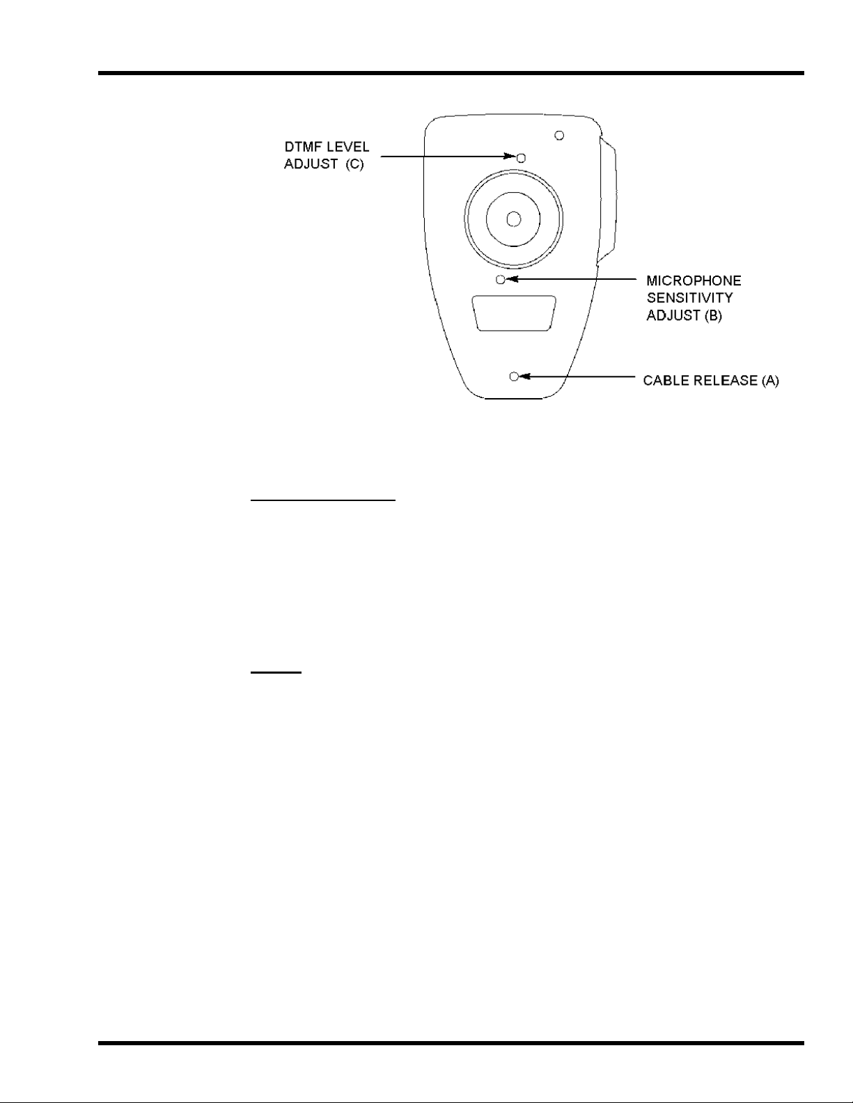
For installations where transmitter input gain requires sensitivity modification, the
microphone has convenient, externally accessible screwdriver controls for independent
adjustment of both microphone and DTMF levels. This eliminates the problem of fixed
audio levels and the necessity for disassembling the microphone for adjustments.
Restricting control access also prevents accidental changes common to external controls.
The microphone is designed for use with most currently available mobile two-way radio
transceivers. For installation convenience, all microphone and signaling functions,
including keypad illumination, are powered directly from the microphone input circuit of
most transmitters, minimizing the need for equipment modification. The microphone is
compatible with a choice of five-conductor, pre-wired, coil-cord MODULINK®cables,
each of which has a telephone-type modular plug on the microphone end, and a choice of
popular transmitter input connectors on the other. The cables are instantly changed or
replaced without soldering.
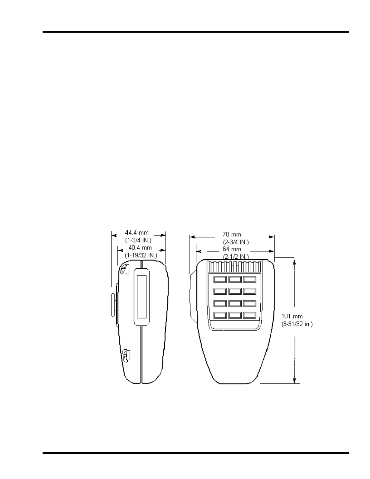
The microphone features attractive, contemporary styling designed to blend with most
radio designs and vehicle interiors. The microphone is ergonomically designed; it fits
naturally and comfortably in the hand and is not affected by heat or humidity. The rugged
ARMO-DUR®case is immune to oil, grease, most fumes and solvents salt spray, sun,
rust and corrosion. It is outstanding in its ability to withstand mechanical shocks and
vibration. The Million-Cycle PIus™ leaf-type switch is a double-pole, single-throw type,
designed to resist the effects of severe operating conditions and constant usage. It has
nickel-silver blades, and its contacts are palladium-alloyed for reliable, oxidation-free
operation.
The microphone’s keypad is made of tough silicone rubber, with durable printed
characters that will last the life of the microphone. The keypad is backlit by red LEDs,
easily visible during night operation and minimizing eye readjustment for night vision.
The microphone is supplied with a small screwdriver for adjusting the microphone
amplifier gain and DTMF level, and for releasing the modular-plug microphone cable
from the microphone.
FEATURES
•Top-Talk Sound Channels™ for clear voice input, easy handling
•Built-in transistor amplifier (powered by carbon-microphone- type circuit)
•Frequency response from 200 to 4,000 Hz, tailored for voice communications
•Illuminated keypad with positive tactile feel and audible confirmation tones
•Auto push-to-talk (APTT) automatically keys transmitter when keypad is depressed

INTRODUCTION
AE/LZB 119 3604/1 R2B 7
•Convenient external microphone gain adjustment accommodates most input circuits
•Simple, easy-to-use continuous-tone dialing
•Externally accessible DTMF level adjustment, independent of microphone gain setting
•Modular-plug coil-cord-easily attached and removed
•Low susceptibility to radio frequency interference
•Low sensitivity to hum pickup
•Rugged Million-Cycle Plus leaf-type switch stands up under severe environments and
constant use
•High-impact ARMO-DUR case - stronger and lighter than diecast metal, comfortable to the
touch in hot or cold weather
•Rugged and dependable under all operating conditions
HANG-UP BUTTON CONNECTION AVAILABLE FOR MICROPHONE HANG-UP
SENSING (MOUNTING BRACKET MUST BE GROUNDED)
Figure 2 – Overall Dimensions

OPERATION
8AE/LZB 119 3604/1 R2B
MICROPHONE CONNECTOR WIRING
Color Function KRY 101 1737/3
Black A– 7
Yellow PTT 3
White Mic Hi 1
Red Switched A+ 6
Drain Mic Lo 2
Blue CG Dis 8
The cable is attached to the microphone by inserting the modular telephone-type plug in the
microphone jack until it locks. To remove the cable from the microphone, insert the small
screwdriver supplied with the microphone in rear case hole "A" just above the cable jack (see
Figure 5) to unlock the plug and withdraw the plug from the jack.
OPERATION
Operation of all microphone and DTMF functions requires that the microphone is connected to the
communications equipment and that the equipment power is turned on. Power application can be
verified by observing keypad LED backlighting.
ADJUSTMENTS
After connection to the communications equipment and with equipment power turned on, the
microphone sensitivity and DTMF output levels should be adjusted with the supplied screwdriver
as follows.
MICROPHONE SENSITIVITY:
Press the push-to-talk button and speak normally into the microphone while observing transmitter
modulation. Adjust the microphone sensitivity control (rear case hole "B" in Figure 5) and repeat
the talk test as required.
DTMF OUTPUT:
Do not press the push-to-talk button. Depress and hold down the "#" key for a continuous tone.
Adjust the DTMF output control (rear case hole "C" in Figure 5) for 60% of rated system
deviation.

OPERATION
AE/LZB 119 3604/1 R2B 9
Figure 3 - Microphone Case (rear)
Voice Transmission
1. Hold the microphone comfortably in the hand, positioned so that the Top-Talk Sound Channels at
the top of the case are near the mouth. The clearest sound is often obtained with the microphone at
the corner of the mouth, with the cable away from the face.
2. Press the push-to-talk button and make sure the equipment is in the transmit mode before
speaking.
3. Release the push-to-talk button before dialing.
Dialing
1. Do not depress the push-to-talk button.
2. Press the desired keypad buttons in sequence. A high-pitched tone will confirm that the code has
been transmitted.
3. When the first keypad button is pushed, the transmitter is automatically keyed. The transmitter
will remain keyed for approximately 1.5 seconds after the button is released.

OPERATION
10 AE/LZB 119 3604/1 R2B
Figure 4 - Exploded View
REPLACEMENT PARTS
Cable and Modular Plug (Figure 4A) KRY 101 1637/21
OPTIONAL ACCESSORY
Mounting Bracket 344A4678P1

OPERATION
AE/LZB 119 3604/1 R2B 11

M/A-COM Wireless Systems
3315 Old Forest Road
Lynchburg, Virginia 24501
(Outside USA, 434-385-2400) Toll Free 800-528-7711
www.macom-wireless.com Printed in U.S.A
Table of contents