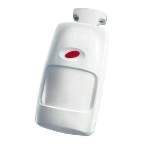
M.a.m.i. Silentron DualTech 5512 User manual

5512 Dual Tech long range outdoor detector
Outdoor Wireless
Intrusion Detector
Dual Technology
the Silentron
manufacturing and minor inventions
M.A.M.I.
5514 Dual Tech wide angle outdoor detector
5514
5512
5514
5512
M000060

WIRELESS DUAL TECHNOLOGY DETECTOR FOR OUTDOOR USE
GENERAL NOTICES AND WARNINGS - Read carefully before using the appliances
Installation: installation and maintenance of these devices must be carried out by qualified technichians. Correct operations is dictated by the
correct installation and positioning . The device can be used outdoor but should be protected from exposure to very high and very low temperatures as
well as tampering
Batteries : these devices use batteries, which are potentially dangerous as they are pollutant and therefore constitute a health hazard if disposed
incorrectly. Replace the batteries with same models observing correct polarity as indicated in the instructions.
Liability: MAMI declines all liability to incidents that were consequent to incorrect installation and/or failure to use the devices within the specifictions
supplied.
1. CONDITIONS FOR USE AND INSTALLATION CRITERIA:
Silentron DualTech is a detector with dual technology (PIR = passive infra-red detector + MW = microwave Doppler detector) developed to detect the
movement of a human in protected areas and it has been designed specifically for outdoor use.
The use of Dual Tech technology and the “double alarm” function reduces the possibility of false alarms due to environmental factors typical of an
outdoor installation (movement of animals of all types, movement of objects and /or meteorological phenomenon).
Correct positioning and adjustment of the unit are fundamental:
Brackets and supports: An adjustable mounting bracket (supplied separately) may be used to further correct the position of the unit.
2. FUNCTIONALITY:
a) General features: The device uses three AA 1.5V alkaline batteries and on detection transmits the alarm via radio, eliminating the need for
physical wiring. The PIR part of the device is permanently on and activates the MW part if an intrusion is detected: the Doppler confirmation of the
existence of a moving mass in the area generates the alarm state. The detection sequence is displayed by the LED on the front of the device, which
changes colour (green-orange-red) through the various passages. The detector could also transmit twice in a 45 seconds window with 2 different
codes:
To reduce battery consumption after every alarm the device is disabled for a while and is restored after no movement is detected in the area for 2
minutes. This to reduce consumption in busy areas. A special version will be available where the 2 minutes are reduced to 5 seconds
b) Double Alarm function: by switching ON the dip 5 the detector transmits a first alarm with a code, and a possible second alarm, detected within 45
seconds, with a different code, as well as two different detectors. In this case the panel can apply the AND function, giving alarm only after the two
different transmissions.
c) Adjustments: the PIR part can be adjusted in RANGE and in PULSE COUNTS, which provide an activation delay. The MW may be adjusted in
RANGE and DELAY, which is the minimum duration time of the movement detected required to trigger the alarm (see drawings).
d) Tamper protection: a magnet fixed to the wall where the mounting bracket is positioned provides tamper protection. When the detector is
correctly positioned on the bracket, the magnet closes a reed positioned inside the device: upward or downward sliding and/or the detachment of the
appliance from the wall causes a "tampering" alarm and the successive "test" state. In the case of detector installation with swivel or angle brackets,
the magnet must be correctly positioned in one of the three possible positions.
e) Opening detection: by opening the powered device, a relevant button controls the transmission of tampering independently from the condition of
the anti-tamper magnet.
f) Test mode: Silentron DualTech is in TEST mode when it is removed from its mounting bracket, where the magnet is located.
The test mode expires 3 minutes after the correct re-positioning of the unit. The LEDs are used to indicate each detection
Note! The device will acknowledge use of the magnetic tamper through an internal reed switch. If it detects the rear magnet for 6 seconds after power
up, the unit will make use of this tamper in its’ normal operation. Should the device not find the magnet, this tamper operation will be disabled.
To re-initiate test mode, simply slide the unit up or down on the bracket for 1second.
Note! The appliance remains permanently in TEST when the internal TAMPER pushbutton is open (box open)
g) Supervision: Silentron DualTech transmits the operating status signal every 40 minutes, which is monitored in the receiver control panels
h) Low Battery signal: the appliance signals via radio to the control panel and locally using 5 beeps that the batteries must be replaced.
3. START-UP – follow these instructions correctly
a) Programming the appliance on the control panel or receiver (also see the instructions of the control panel/receiver used):
·Open the appliance by loosening the screws on the bottom and open the lid of the battery compartment.
·Place the control panel in PROGRAMMING mode, in detector learning condition on the desired zone
·Extract the battery isolating film, powering the appliance: programming will be confirmed by a Beep from the control panel.
·Terminate the procedure by assigning the name to the detector (if using the HomeGuard). Close the battery compartment.
b) Positioning:
Choose the position and the height of installation of the device in relation to the area to be protected keeping in mind of the area covered by the device
PIR section (infra-red detector). It has a central detection beam of over 20m and a series of 4+4 side detection areas of up to 10m. The highest
sensitivity of the device is achieved when the intruder crosses the areas perpendicularly. The MW part (microwave) entirely covers the zone, but it is
activated only after a detection of the infrared (see 2a - Long range version).
All the detection areas operate on the same level, therefore the protected zone resembles an anomalous open fan, with the central detection area
twice the length of others. When the device is installed vertically (normal position)the detection areas are parallel to the ground. The height of
installation must be determined according to the area that should be left not protected to allow movement of small animals.
When the device is installed horizontally it forms a vertical or diagonal “curtain”
Do not place the device in direct sunlight to prevent internal overheating (greenhouse effect): this does not damage the appliance but decreases the
sensitivity of PIR section . Where possible protect the detector from extreme weather conditions and from gutter overflows
c) Adjustments (see diagram):
To check the adjustments, use the devices’s LED, which must be placed in TEST state: The green LED indicates the PIR detection: successively it
changes to orange when the movement is confirmed by the MW part; when the delay time has passed (PT2) the LED turns red indicating the alarm
transmission. The detection tests must be performed with the device closed.
·Adjust the PIR sensitivity (dip-switch 2), with pulse count on 1 (off), limiting the range to what is strictly necessary.
·Adjust the sensitivity of the MW part (RANGE - PT1), with activation time at minimum, as a consequence of the previous adjustment.
·Close the appliance, position it and check the coverage of the protected area (watch the LED) , by moving the same: for a precise definition of the
detection area it is recommended that you move around .Iif necessary open the unit and reduce or increase the range and repeat the previous
tests.
M000060

21 Hubert Mathew Road
Illiondale
1609
South Africa
Tel: +27 11 452 4737
Fax: +27 11 452 4738
manufacturing and minor inventions
M.A.M.I.
WASHER
LOCK WASHER
WASHER
LOCK WASHER
WALL PLUG
WALL PLUG
SILENTRON
MOUNTING
BRACKET
ADJUST FOR
INCLINATION
ADJUST FOR
INCLINATION
SUN / RAIN SHIELD
SILENTRON
TAMPER
MAGNET
SILENTRON
OUTDOOR
DETECTOR
SLIDE
INTO
BRACKET
FRONT VIEW
TIPICALLY 1.3 m FROM GROUND
MOUNTING BRACKET
for
SILENTRON WIRELESS
OUTDOOR DETECTOR
d) LED exclusion: for safety reasons and to reduce power consumption disable the LED indication. This is done with dip-switch 4 set to ON.
LEDs remain functional in TEST mode.
e) Temperature compensation: the function consists in the automatic adjustment of the PIR sensitivity when the temperature in the
device exceeds 30°C . this function is enabled by placing dip-switch 6 to ON. In case of exposure to the sun the temperature inside the
appliance can be much higher than the environment temperature.
TECHNICAL FEATURES (see diagrams also)
Power supply: 4.5V via three AA 1.5V 2.2Ah batteries – Current consumption 70uA at rest, 40mA in transmission – Autonomy of about 2
years, which could be greatly reduced in the case of a busy area and with LED active during normal functioning (dip-switch 4).
Functions: indication of movement in the protected area (intruder alarm) – tampering – supervision – flat batteries.
Radio transmissions: coded at 64 bit in simultaneous Dualband frequency – frequencies and power in compliance with the regulations.
Range of about 100 m in free space and without interference on the frequency bands.
Warning! To keep the declared environmental class, it is necessary to tighten properly the screws closing the device !
M000060

14
m
1
2
3
4
246 8 10 12 14 16 18 20 22
P.I.R. ALARM AREA : h1.3m
24 6 8 10 12 14 16 18 20 22
4
2
0
2
4
6
m
MW (RADAR) RANGE
PT1 min<12m max>20
6
microwave
PIR
24 6 8 10 12 14 16 18 20 22
4
2
0
2
4
6
m
MW (RADAR) RANGE
PT2 min<1sec max>2sec
6
microwave
PIR
m
1
2
3
4
246 8 10 12 14 16 18 20 22
P.I.R. ALARM AREA : h0.8m
6 5 4 3 2 1
on
PIR
LED
PT1 PT2
5512
TAMPER
DISABLED 1
6
24 6 8 10 12 14 16 18 20 22
4
2
0
2
4
6
m
PIR
RANGE
6
PIR
3 2 1
3 2 1
OFF =MIN ON=MAX
2
2
2sec.~
1sec.~
4
5512 Dual Tech long range outdoor detector
PUSH TO OPEN
3x ALK size AA 1.5V
M000060

5514 Dual Tech wide angle outdoor detector
m
1
2
3
4
m
1
2
3
4
10 11
MW (RADAR) RANGE
12
PT 1
MIN
12 3 4 5 6 7 8 9
2
1
0
1
2
3
m
3
PT 1
MAX
10 11
MW (RADAR) RANGE
12
PT 2
MIN
0.25sec
12 3 4 5 6 7 8 9
2
1
0
1
2
3
m
3
PT 2
MAX
2.5sec
4
3
2
1
0
1
2
3
1 2 3 4 5 7912m11
6810
4m
PIR
RANGE
3 2 1
3 2 1
OFF =MIN ON=MAX
2
2
246 8 10 12 14 16 18 20 22
P.I.R. ALARM AREA : h1.3m
246 8 10 12 14 16 18 20 22
P.I.R. ALARM AREA : h0.8m
6 5 4 3 2 1
on
PIR
LED
PT1
PT2
5514
TAMPER
1
6
PT 1
disabled
3x ALK size AA 1.5V
PUSH TO OPEN
M000060

21 Hubert Mathew Road
Illiondale
1609
South Africa
Tel: +27 11 452 4737
Fax: +27 11 452 4738
manufacturing and minor inventions
M.A.M.I.
M000060
This manual suits for next models
1
Table of contents
Popular Security Sensor manuals by other brands
Takex
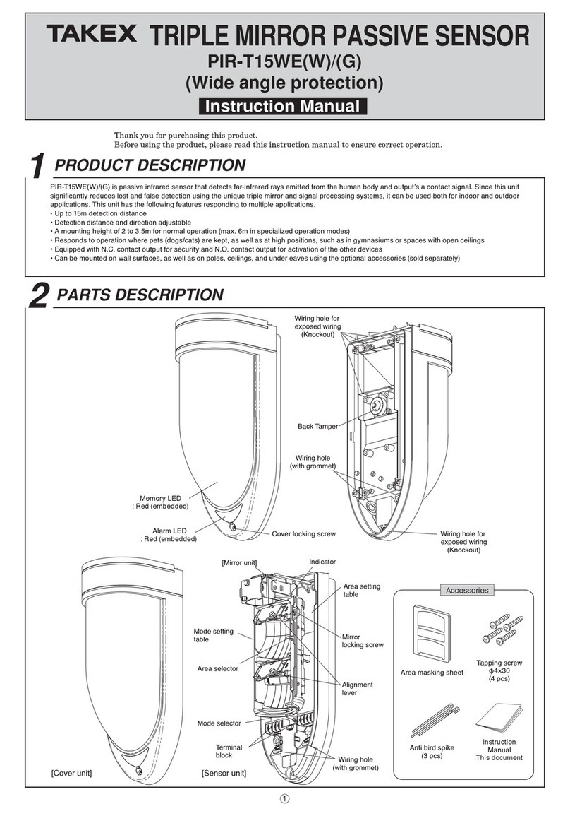
Takex PIR-T15WE(W) instruction manual
Niko
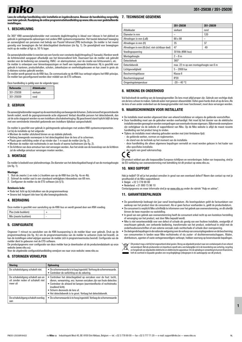
Niko 351-25038 manual
Wenglor
Wenglor IR2D001 operating instructions

Elektrotechnik Schabus
Elektrotechnik Schabus SHT 5001 operating instructions
System Sensor
System Sensor 1112/24D Installation and maintenance instructions
elobau
elobau 1655 V Series Translation of the original operating instructions


