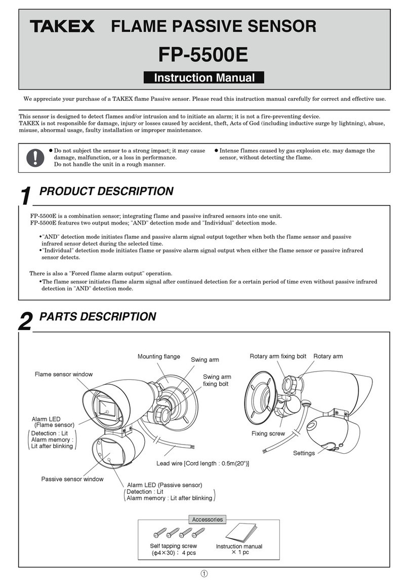
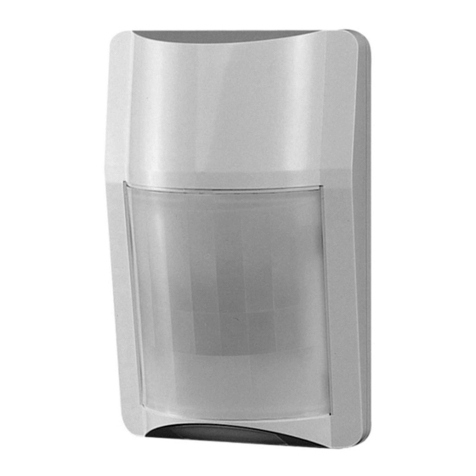
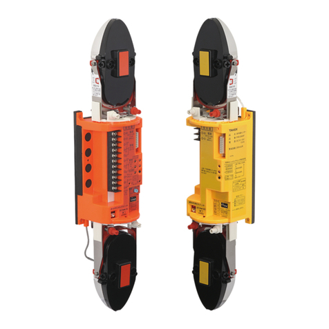
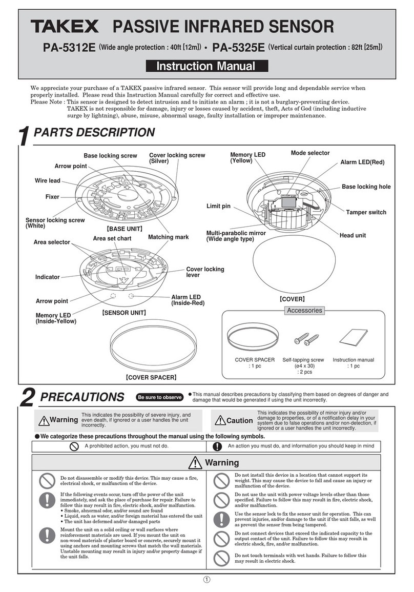
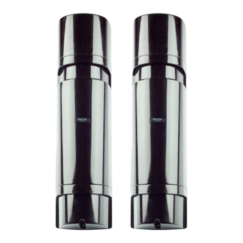
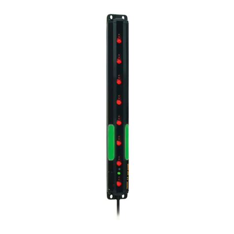
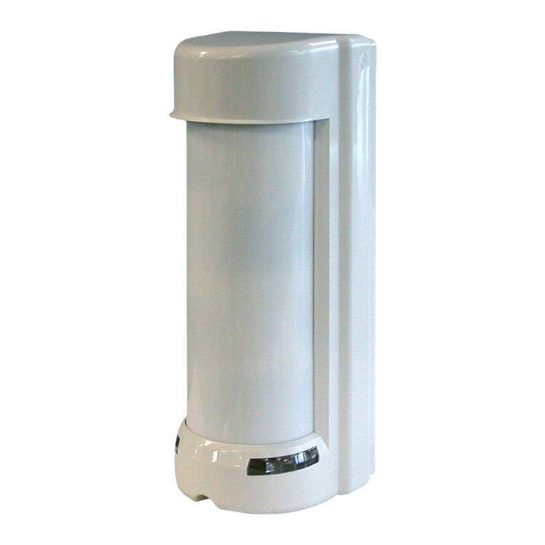
Takex PIR-T15WE(W) User manual

3,57:(:*LVSDVVLYHLQIUDUHGVHQVRUWKDWGHWHFWVIDULQIUDUHGUD\VHPLWWHGIURPWKHKXPDQERG\DQGRXWSXW·VDFRQWDFWVLJQDO6LQFHWKLVXQLW
VLJQLILFDQWO\UHGXFHVORVWDQGIDOVHGHWHFWLRQXVLQJWKHXQLTXHWULSOHPLUURUDQGVLJQDOSURFHVVLQJV\VWHPVLWFDQEHXVHGERWKIRULQGRRUDQGRXWGRRU
DSSOLFDWLRQV7KLVXQLWKDVWKHIROORZLQJIHDWXUHVUHVSRQGLQJWRPXOWLSOHDSSOLFDWLRQV
• Up to 15m detection distance
'HWHFWLRQGLVWDQFHDQGGLUHFWLRQDGMXVWDEOH
$PRXQWLQJKHLJKWRIWRPIRUQRUPDORSHUDWLRQPD[PLQVSHFLDOL]HGRSHUDWLRQPRGHV
5HVSRQGVWRRSHUDWLRQZKHUHSHWVGRJVFDWVDUHNHSWDVZHOODVDWKLJKSRVLWLRQVVXFKDVLQJ\PQDVLXPVRUVSDFHVZLWKRSHQFHLOLQJV
(TXLSSHGZLWK1&FRQWDFWRXWSXWIRUVHFXULW\DQG12FRQWDFWRXWSXWIRUDFWLYDWLRQRIWKHRWKHUGHYLFHV
&DQEHPRXQWHGRQZDOOVXUIDFHVDVZHOODVRQSROHVFHLOLQJVDQGXQGHUHDYHVXVLQJWKHRSWLRQDODFFHVVRULHVVROGVHSDUDWHO\
>&RYHUXQLW@
Memory LED
: Red (embedded)
$ODUP/('
: Red (embedded) &RYHUORFNLQJVFUHZ :LULQJKROHIRU
H[SRVHGZLULQJ
.QRFNRXW
:LULQJKROHIRU
H[SRVHGZLULQJ
.QRFNRXW
:LULQJKROH
ZLWKJURPPHW
%DFN7DPSHU
>6HQVRUXQLW@
0RGHVHWWLQJ
WDEOH
$UHDVHWWLQJ
WDEOH
0RGHVHOHFWRU
Indicator
$UHDVHOHFWRU
$OLJQPHQW
OHYHU
>0LUURUXQLW@
7HUPLQDO
EORFN :LULQJKROH
ZLWKJURPPHW
Mirror
ORFNLQJVFUHZ
Accessories
7DSSLQJVFUHZ
Ѯð
SFV
Instruction
0DQXDO
This document
$UHDPDVNLQJVKHHW
(1 sheet)
$QWLELUGVSLNH
SFV
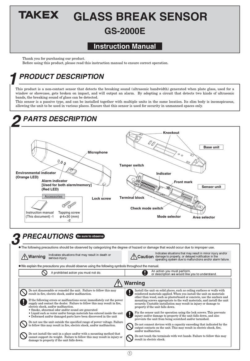
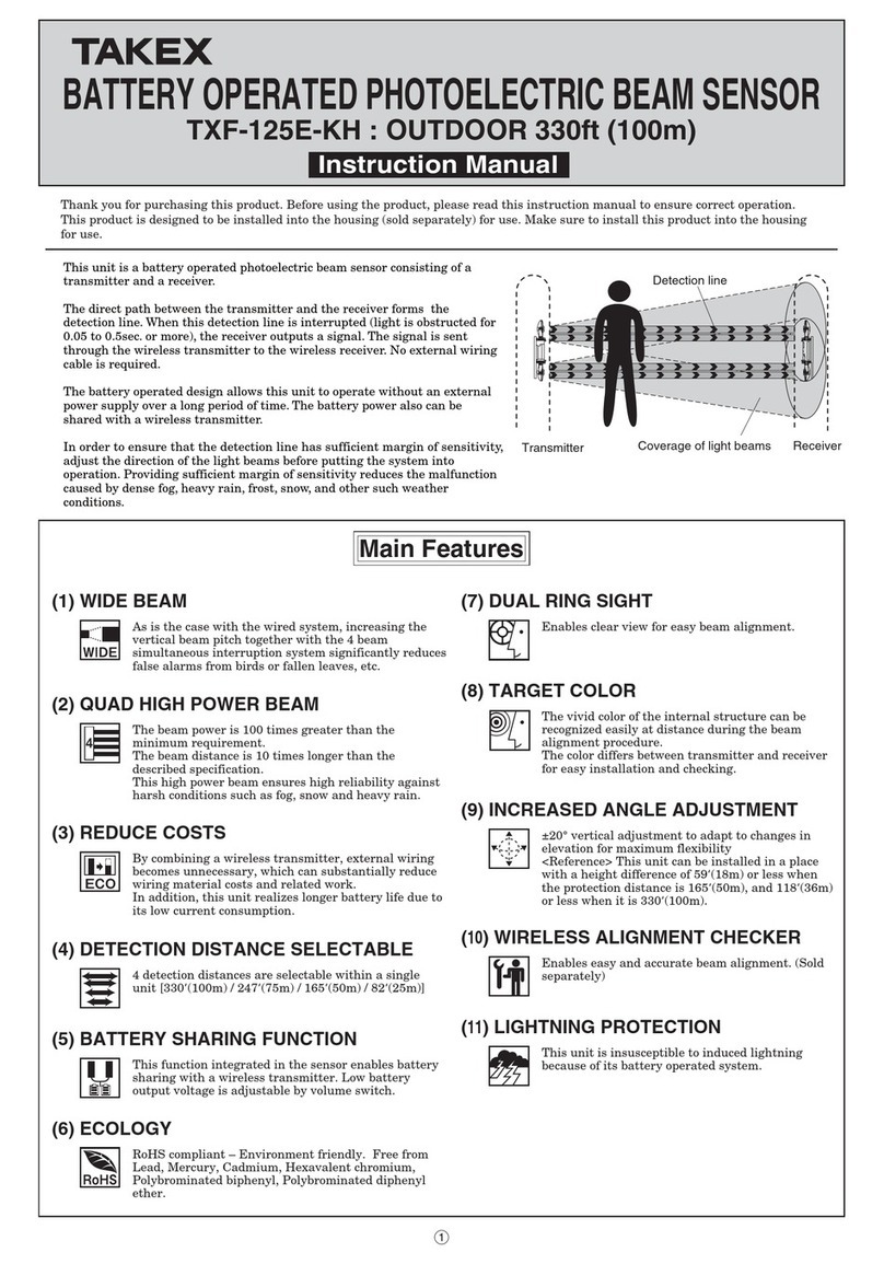
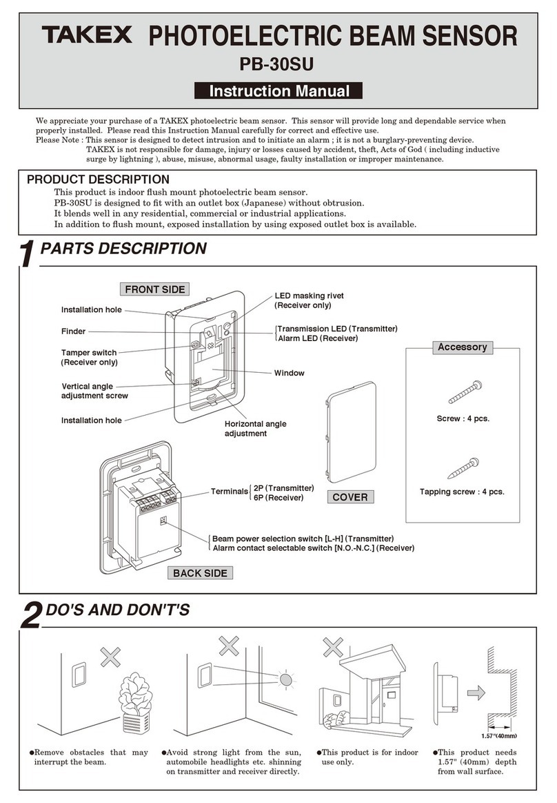
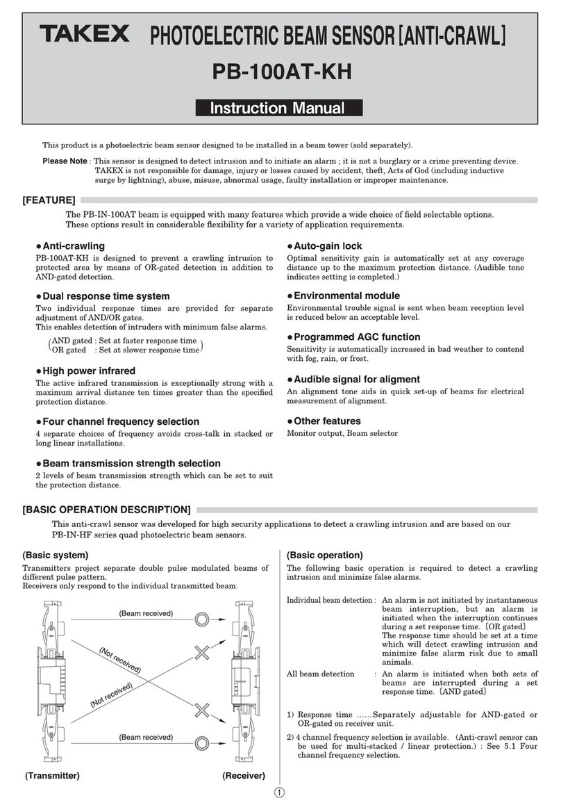
Thank you for purchasing this product.
Before using the product, please read this instruction manual to ensure correct operation.
TRIPLE MIRROR PASSIVE SENSOR
Instruction Manual
PIR-T15WE(W)/(G)
(Wide angle protection)
1PRODUCT DESCRIPTION
2PARTS DESCRIPTION
1

3HWVVXFKDVGRJVFDWVDQGELUGV
H[FOXGLQJWKHSHWPRGH
6KLHOGLQJREMHFWV 3ODFHVWKDWSHRSOHFDQHDVLO\WRXFK
6WURQJOLJKWWKDWKLWVWKHVHQVRU
6WURQJYLEUDWLRQDQGRUHOHFWULFQRLVH
Warning
Caution
Do not use the unit with power voltage levels other than those
specified. Failure to follow this may result in fire, electric shock,
and/or malfunction.
Do not connect devices that exceed the indicated capacity to the
output contact of the unit. Failure to follow this may result in
electric shock, fire, and/or malfunction.
Do not touch terminals with wet hands. Failure to follow this
may result in electric shock.
If the following errors/malfunctions occur, power off the unit
immediately, and contact your dealer.
Failure to follow this may result in fire, electric shock, and/or
malfunction.
• Smoke, abnormal odor, and/or sound are found
• Liquid, such as water, and/or foreign material has entered the
unit
• The unit is deformed and/or parts are damaged
Do not disassemble or modify the unit.
Failure to follow this may result in fire, electric shock, and/or
malfunction.
Mount the unit on a solid ceiling or wall surfaces where
reinforcement materials are used. If you mount the unit on
non-wood plaster board or concrete, securely mount it using
anchors and mounting screws that match the wall materials.
Failure to follow this may result in injury and/or property
damage if the unit falls.
Do not install the unit in a place and/or with a mounting
method that cannot support its weight.
Failure to follow this may result in injury and/or property
damage when the unit falls.
Do not apply impact to the unit.
Applying strong impact to the unit may result in performance
deterioration and/or damage to the unit.
The unit may not operate properly near devices that generate a
strong electric or magnetic field. Also, devices near the unit may
not operate properly due to the magnetic field and/or magnetism
generated from the unit.
Make sure to check it before operation.
Make sure to perform sufficient operation checks on the whole
system before operation.
Securely conduct installation work according to the instruction
manual. Also, make sure to use the supplied accessories and
specified components. Failure to follow this may result in injury
and/or property damage in the event of fire or electric shock or if
the unit falls.
Contact qualified personnel for any electrical work necessary for
installation, if required.
Failure to follow this may result in fire and/or electric shock.
Do not install the unit in places subject to oil smoke or steam,
high humidity, and/or a lot of dust. Electricity transmitted
through oil, water, and/or dust may result in fire, electric shock,
and/or false operation.
Do not perform aerial wiring of power and signal cables. Failure
to follow this may result in electric shock, fire, and/or
malfunction.
Passive infrared sensors are designed to detect changes of
far-infrared ray energy. Energy changes largely when the
human body moves across the detection area. However, energy
does not change greatly when the human body comes closer in a
straight line, or stops.
In addition, if the detection area environment generates similar
changes due to certain factors, the unit will issue an alarm
without being able to judge properly.
Avoid installing the unit in the following places. Otherwise, false
detection may occur.
• Places subject to strong direct or reflected light (sunlight,
spotlight)
• Places subject to rapid temperature fluctuations (air outlets of
air-conditioning equipment, etc.)
• Places where moving objects are included in the detection area
(trees, branches and leaves, laundry, etc.)
• Places subject to strong vibration and/or electric noise
• Places where dogs, cats, birds, and/or automatic cleaning
robots may pass (excluding in the pet mode operation)
• Places where shielding objects (including glass and
transparent resin, etc.) are included in the detection area
(shading parts will not be detected)
• Places where the sensor part looks inclined from the front
view (the area cannot be properly configured)
• Places that intruders can easily touch
Set the area within the rated detection distance range according
to the instruction manual. If you use the unit outside the
specified range, an appropriate area will not have been
configured, and the unit may operate unsteadily, and/or
detection may fail.
$LURXWOHWVRIDLUFRQGLWLRQLQJ
HTXLSPHQW
6XQOLJKWUHIOHFWLRQ
7UHHVEUDQFKHVDQGOHDYHVODXQGU\
Warning Caution
$SURKLELWHGDFWLRQ\RXPXVWQRWGR $QDFWLRQ\RXPXVWGRDQGLQIRUPDWLRQ\RX
VKRXOGNHHSLQPLQG
3PRECAUTIONS 7KLVPDQXDOGHVFULEHVSUHFDXWLRQVE\FODVVLI\LQJWKHPEDVHG
RQGHJUHHVRIGDQJHUDQGGDPDJHWKDWZRXOGEHJHQHUDWHGLI
XVLQJWKHXQLWLQFRUUHFWO\
Be sure to observe
7KLVLQGLFDWHVWKHSRVVLELOLW\RIVHYHUH
LQMXU\DQGHYHQGHDWKLILJQRUHGRUD
XVHUKDQGOHVWKHXQLWLQFRUUHFWO\
7KLVLQGLFDWHVWKHSRVVLELOLW\RIPLQRULQMXU\DQGRU
GDPDJHWRSURSHUWLHVRURIDQRWLILFDWLRQGHOD\LQ
\RXUV\VWHPGXHWRIDOVHRSHUDWLRQVDQGRU
QRQGHWHFWLRQLILJQRUHGRUDXVHUKDQGOHVWKHXQLW
LQFRUUHFWO\
We categorize these precautions throughout the manual using the following symbols.
Caution
Refer to the detection area chart, and select the installation
location. Then, check the actual operation, and adjust the
appropriate area.
Install the unit where the
detection area faces toward a
place intruders may pass
through.
After installation, make sure
to adjust the detection area
and perform sufficient
operation check.
This unit is for wall installation. When installing it on poles,
ceilings, or under eaves, use the specified attachments (sold
separately).
This unit has a rainproof structure. Not a waterproof structure.
Do not hose it directly. Do not use the unit in places subject to
water and/or constant high humidity, such as bathroom. Failure
to follow this could result in malfunction.
In order to maintain the rainproof structure of this unit, install
it in the correct direction. Installing it sideways or upside down
may result in malfunction.
Apply caulking to wiring holes based on the installation wall
material, if necessary, in order to maintain rainproof
performance.
• When the surface in the area is
downward-sloping from the sensor side
ࠉЍThe detection distance becomes longer
• When the surface in the area is
upward-sloping from the sensor side
ࠉЍThe detection distance becomes shorter
Mount the unit straight so that it does not look inclined from
the front and side view.
Note that the detection distance depends on the following
factors.
ەSensor installation height
(The higher within the rated range, the longer the detection
distance)
ەSensor mounting status and surface gradient in the area
Adjust the detection area so
that it does not go beyond
the site.
(Unexpected objects may be
detected)
4DETECTION AREA
’P
’P
’P
’P
’P
’P
’P
’P
’P
’P
’P
’P
”P
’P
’P
’P
’P
’P
’P
’P
’P
’P
’P
’
P
0
&(17(5=21(
’
P
0
&(17(5=21(
’
P
’
P
0
&(17(5=21(
0
&(17(5=21(
’
(5m) ’
P ’
(15m)
’
(5m) ’
P ’
(15m)
’
(5m) ’
P ’
(15m)
’
(5m) ’
P ’
(15m)
NormalOperation
Side view Top view
〈Low position mode〉
Specialized Operation 〈Pet mode〉
〈Highdensitymode〉
〈Hight position mode〉

:KHQWKHUHDUHIDOVHRSHUDWLRQIDFWRUVZLWKLQWKHVSHFLILHGGHWHFWLRQDUHDRU\RXZDQWWRDGMXVWWKHGHWHFWLRQGLVWDQFHLQWKHSHW
PRGHPDVNWKHGHWHFWLRQDUHDZLWKVXSSOLHGDUHDPDVNLQJVKHHW
①
③
②
$UHDPDVNLQJVKHHW
①
③
②
:KHQPDVNLQJHDFKGHWHFWLRQDUHDIURP①to ③DWWDFKWKHDUHDPDVNLQJVKHHWWRWKH
VXUIDFHRIWKHPLUURUXQLWFRUUHVSRQGLQJWRWKHGHWHFWLRQDUHD)LWRQHHQGRIWKHVKHHWWRWKH
DUURZSRVLWLRQDQGIL[LQWRSODFH
%HFDUHIXOQRWWROHDYHGLUWRURLOVXFKDVZLWKILQJHUSULQWVRQWKHPLUURUVXUIDFHZKHQ
DWWDFKLQJWKHVKHHW
* $OZD\VVHWWKHGHWHFWLRQGLVWDQFHWR’PLQWKHSHWRSHUDWLRQPRGH:KHQDGMXVWLQJWKHGHWHFWLRQGLVWDQFHPDVNWKH
GHWHFWLRQDUHDZLWKVXSSOLHGDUHDPDVNLQJVKHHWLQVWHDGRIDGMXVWLQJZLWKWKHDUHDVHOHFWRU
■Masking method of the detection area
[Side view]
[Top view]
①
③
②
①②
③
$SSUR[
’(7m)
$SSUR[
’P
’(15m)
In the case
of the
LQVWDOODWLRQ
KHLJKWRI
’P
[Side view]
[Top view]
$SSUR[’P
In case of
LQVWDOODWLRQ
KHLJKWRI
’P
■
Precautions on the detection area setting
7RVHWWKHGHWHFWLRQGLVWDQFHOHVVWKDQWKHPLQLPXPRIWKH
DUHDVHWWLQJWDEOHDWWDFKWKHPDVNLQJVKHHWRQWKHVXUIDFH
RIWKHPLUURUXQLW
(5HIHUWR´$'-8670(172)'(7(&7,21$5($µ)
$WWDFKWKHDUHDPDVNLQJVKHHWLQRUGHUIURPWKHORQJHVW
SDUWRIWKHGHWHFWLRQDUHDDQGDGMXVWWKHGHWHFWLRQ
GLVWDQFH
●Detection area distance adjustment
●Near area cancellation setting
:KHQWKHQHDUDUHDVHWWLQJRIPRGHVHOHFWRULV
FDQFHOOHGWKHGHWHFWLRQDUHDLVFRQILJXUHGDVLQWKHILJXUH
RQWKHULJKW:LWKWKLVVHWWLQJGHWHFWLRQGRHVQRWRFFXULQ
QHDU]RQHVRIWKHGHWHFWLRQDUHDEXWRQO\LQIDU]RQHV
6LQFHWKHGHWHFWLRQ]RQHH[WHQGVXQWLOLWKLWVWKHJURXQGRU
ZDOOVXUIDFHWKHXQLWPD\GHWHFWREMHFWVHYHQLQSODFHV
EH\RQGWKHVSHFLILHGGLVWDQFH,QRUGHUWRDYRLGXQH[SHFWHG
GHWHFWLRQDGMXVWWKHDUHDVXIILFLHQWO\
●Detection area range
,QWKHVHWWLQJRILQVWDOODWLRQ
KHLJKW’PDQGGHWHFWLRQ
GLVWDQFH’(15m)
1HDUDUHDVHWWLQJFDQFHOOHG
RIPRGHVHOHFWRU

/RRVHQWKHFRYHUORFNLQJVFUHZDQGUHPRYH
WKHFRYHUXQLW
3XWWKHZLUHWKURXJKWKHJURPPHWLQWKHZLULQJ
KROHDWWKHERWWRPRIWKHVHQVRUXQLW%UHDN
WKHPRXQWLQJKROHNQRFNRXWRIWKHVHQVRUXQLW
DQGPRXQWLWXVLQJWKHVXSSOLHGWDSSLQJ
VFUHZV
* For open wiring, break the
knockout on the rear side
of the sensor unit, and
pull the wire through it.
&RQQHFWWKHZLUHVWRHDFK
WHUPLQDO
5HIHUWR´:,5,1*µ
6HWWKHGHWHFWLRQDUHDDQGIXQFWLRQVDFFRUGLQJ
WRWKHLQVWDOODWLRQVLWH5HIHUWR´'(7(&7,21
$5($µDQG´)81&7,21µ
$5($µ´$'-8670(172)'(7(&7,21
5HSODFHWKHFRYHUXQLW
DQGIL[LWE\WLJKWHQLQJ
WKHFRYHUORFNLQJ
VFUHZV
*When installing
outdoors, mount
the anti bird spike
above the cover
unit. Turn the anti
bird spike and
tighten it.
When mounting on the pole
[Use the pole attachment]
When mounting on the ceiling or under eaves
[Use the ceiling attachment]
When mounting the unit on a vertical pole, use the pole attachment
(sold separately). The unit can be mounted on poles of Dia 15”to 19”
(φ38 to φ49mm) and Dia 15.7”to 55”(φ40 to φ140mm).
* Mount the sensor so that its mounting surface is placed vertically.
When mounting on the ceiling or under eaves,
use the ceiling attachment (sold separately).
* Mount the sensor so that its mounting surface
is placed vertically.
The installation height and adjustable detection distance depend on the
operation mode. Carefully check the operation mode and detection area
setting before installation and area setting.
:KHQWKHGHWHFWLRQDUHDDQGIXQFWLRQVVHWWLQJV
DUHFRPSOHWHGJRWRVHFWLRQ´23(5$7,21
&+(&.µ
* Installation height of the sensor should be
within 8.3’to 10’(2.5 to 3.0m) in the pet mode.
3ROH
attachment
%3)
3ROHGLDPHWHU
Dia 15”WR”
ѮWRPP
3ROH
attachment
%3
3ROHGLDPHWHU
'LD”to 55”
ѮWRPP
■
Mounting method
When using the pole
attachment BP-22F (sold
separately), break the
knockout on the rear side
of the sensor unit, and
attach it.
* Adjust the sensor installation height using
the center of the sensor housing as a guide.
8VHWKHXQLWZLWKWKHFRUUHFWRSHUDWLRQPRGHVHWWLQJ6HOHFWRSHUDWLRQPRGHWRXVHDQGSHUIRUPWKH
VHWWLQJFRUUHFWO\7KLVXQLWFDQEHRSHUDWHGIURP①to ④PRGHVDVIROORZV
Normal operation modes
7KHUHDUHORZDQGKLJKSRVLWLRQPRGHVDFFRUGLQJWRWKHLQVWDOODWLRQKHLJKW
①Low position mode
This can be used to reduce false detection caused by small animals. Set this mode when the
unit is mounted at a installation height of 6.6’to 9’(2.0 to 2.7m.)
②High position mode
This can be used to reduce false detection caused by small animals. Set this mode when the
unit is installed at a mounting height of 9’to 11.5’(2.7 to 3.5m.)
* When the mounting height is 9’(2.7m), either low or high position mode can be set.
Specialized operation modes
7KLVLVDQRWKHURSHUDWLRQPRGHEHVLGHVQRUPDORQH7KHUHDUHSHWPRGHDQGKLJKGHQVLW\PRGH
③Pet mode
Set this mode in order to reduce false detection caused by pets (dogs, cats) and small
animals. Install the unit at a installation height of 8.3’to 10’(2.5 to 3.0m.)
④High density mode
Set this mode in order to significantly reduce non-detection of the human body in the
detection area. The unit can be installed at a mounting height of 6.6’to 20’(2.0 to 6.0m.)
Choose among the above four operation modes, and set with the mode selector. (Refer to “7
FUNCTION”)
Put the wires for power input and alarm
output through the wiring hole on the left,
and for tamper output and starting output
on the right. Be careful not to cross the
wires.
5INSTALLATION
5
:LULQJ
3RZHU$ODUP
:LULQJ
7DPSHU([WHUQDO
&HQWHURI
the sensor
,QVWDOODWLRQKHLJKW
Pole
attachment
BP-22F
Ceiling
attachment
KP-32
Pole
attachment
BP-22F
Normal Operation Specialized Operation
Low Position Mode
High Position Mode
Pet Mode
High Density Mode
Mounting Height 6.6-9ft(2.0-2.7m)
9-11.5ft(2.7-3.5m) 8.3-10ft(2.5-3.0m) 6.6-20ft(2.0-6.0m)
Small Animal Tolerance
●●●
Pet Immune ●
Creep Zone Detection
●(Selectable) ●(Selectable) ●
Near Area Cancellation
●(Selectable) ●(Selectable)

* When 2 or more units are connected, the wiring distance is calculated
by dividing above value by number of units
3RZHULQSXWQRQSRODULW\
WR9'&0D[P$
$ODUPRXWSXW
&RQWDFWPHWKRG 'U\VHPLFRQGXFWRUFRQWDFW121&VHOHFWDEOH
&RQWDFWRSHUDWLRQ2QHVKRWRSHUDWLRQVHFZKHQGHWHFWLQJLQWUXVLRQ
&RQWLQXRXVRXWSXWLQWKHHYHQWRIFRYHUPRQLWRUHUURU
XQWLOGHWHFWLRQRSHUDWLRQDIWHUWKHFRYHULVFORVHG
&RQWLQXRXVRXWSXWLQWKHHYHQWRIVHOIGLDJQRVLVHUURU
XQWLOQRUPDOUHFRYHU\
&RQWLQXRXVRXWSXWLQWKHHYHQWRISRZHUYROWDJHHUURU
XQWLOQRUPDOUHFRYHU\
&RQWLQXRXVRXWSXWLQWKHHYHQWRIORQJWHUPGLDJQRVLVHUURU
XQWLOWKHFRYHULVRSHQ
&RQWLQXRXVRXWSXWLQWKHHYHQWRIDUHDFKHFNHUSRVLWLRQHUURU
XQWLOQRUPDOUHFRYHU\
&RQWDFWUDWLQJ 9$&'&$UHVLVWLYHORDG
EXLOWLQFRQWDFWSURWHFWLYHUHVLVWRUї
Tamper output
&RQWDFWPHWKRG 'U\PHFKDQLFDOFRQWDFW1&
&RQWDFWRSHUDWLRQ&RQWLQXRXVO\RXWSXWZKHQWKHFRYHULVRSHQ
XQWLOWKHFRYHULVFORVHG
&RQWDFWUDWLQJ 9$&'&$UHVLVWLYHORDG
EXLOWLQFRQWDFWSURWHFWLYHUHVLVWRUї
([WHUQDORXWSXW
&RQWDFWPHWKRG 'U\VHPLFRQGXFWRUFRQWDFW12
&RQWDFWRSHUDWLRQ2QHVKRWRSHUDWLRQVHF2IIGHOD\RSHUDWLRQVHF
VHOHFWDEOHZKHQGHWHFWLQJLQWUXVLRQ
(DFKHYHQWRXWSXWLVLVVXHGDVDODUPRXWSXW
&RQWDFWUDWLQJ 9$&'&$UHVLVWLYHORDG
EXLOWLQFRQWDFWSURWHFWLYHUHVLVWRUї
6WIRING
■
Terminal configuration
■Standard connection
&RQQHFWLRQH[DPSOHVZKHQXVLQJWZRXQLWV
■
Wiring distance between sensor and power supply
Area checker
7KLVIXQFWLRQFDQEHXVHGWRYLVXDOO\FKHFNWKHVHQVLWLYH]RQHLQWKH
GHWHFWLRQDUHDE\OLJKWLQJWKH/('HTXLSSHGLQVLGHWKHPLUURUXQLW
Self diagnosis
7KLVIXQFWLRQLVXVHGWRPRQLWRUHUURUVZLWKGHWHFWLRQHOHPHQWVRU
VHQVRUFLUFXLWVDQGGDPDJHGGLVFRQQHFWHGZLULQJ,IGDPDJHRU
GLVFRQQHFWLRQRFFXUVDODUPZLOOEHLVVXHGXVLQJDODUPRXWSXWDQG
DODUP/('5HVHWWKHSRZHURIWKHVHQVRUGXULQJDODUPWRVWRSLW
$IWHUZDUPLQJXSRSHUDWLRQILQLVKHVPRQLWRULQJZLOOVWDUWDJDLQ
:KHQDQDODUPLVLVVXHGFKHFNWKHVHQVRURSHUDWLRQLPPHGLDWHO\
Area checker position monitoring
This function is used to issue an DODUPXVLQJDODUPRXWSXWDQGDODUP
/('ZKHQWKHDUHDFKHFNHUXQLWHTXLSSHGLQVLGHWKHPLUURUXQLWKDV
QRWUHWXUQHGWRWKHRULJLQDOSRVLWLRQ
5HIHUWR´$'-8670(172)'(7(&7,21$5($µ
Low voltage monitoring
This function is used to issue an DODUPZKHQWKHSRZHUYROWDJHOHYHO
VXSSOLHGWRWKHVHQVRUGHFUHDVHVDEQRUPDOO\WRDSSUR[9RU
OHVV$ODUPLVLVVXHGXVLQJDODUPRXWSXWDQGDODUP/('EHIRUHWKH
VHQVRURSHUDWLRQEHFRPHVXQVWDEOH,WZRUNVHYHQGXULQJWKH
ZDUPLQJXSRSHUDWLRQ:KHQWKHSRZHUYROWDJHOHYHOUHWXUQVWR
QRUPDOGXULQJDQDODUPWKHZDUQLQJDXWRPDWLFDOO\VWRSV:KHQDQ
DODUPLVLVVXHGFKHFNWKHSRZHUYROWDJHLPPHGLDWHO\
■
Function
7FUNCTION
Extra terminal
/('FRQWUROLQSXW/&
&RQWUROOLJKWLQJRQRIIRIWKHDODUP/('
&RQQHFWWRWKHSRVLWLYHVLGHRIWKHSRZHUVXSSO\
&RQWUROOHU
3RZHU
output
}
6LJQDOLQSXW
6HQVRU
1&
6HQVRU
1&
AWG20(Dia0.8mm)
AWG18(Dia1.0mm)
AWG17(Dia1.1mm)
AWG16(Dia1.25mm)
SupplyVoltage12VDC
2850ft(870m)
4400ft(1340m)
5300ft(1600m)
7000ft(2130m)
SupplyVoltage24VDC
14000ft(4270m)
22000ft(6700m)
27000ft(8230m)
33000ft(10000m)
LED CONTROL FUNCTIONS
&RQQHFWWHUPLQDO⑤WKURXJKDQH[WHUQDOFRQWDFWVZLWFKZLWK
SRZHU
OPERATION
Turn the Mode selector ①OFF
When the switch is turned ON, the alarm LED lights at alarm.
When the switch is turned OFF, the alarm LED does not light.

21 (QDEOHVOLJKWLQJ
2))/LJKWLVDOZD\VRII
,QGLFDWHVDEQRUPDORXWSXWRQO\
',3VZLWFK
212))
)DFWRU\VHW
Alarm LED setting (1 of mode selector 1)
6HWVWKHDODUP/('UHGWROLJKW
RQRII
21 (QDEOHG
6HWVWKHOLJKWLQJRSHUDWLRQ
SDWWHUQDWRIPRGHVHOHFWRU
2))'LVDEOHG
6HWVWKHPHPRU\IXQFWLRQWREH
HQDEOHGGLVDEOHG
Memory function setting (2 of mode selector 1)
',3VZLWFK
212))
)DFWRU\VHW
8VHWKHPRGHVHOHFWRUVDQGLQVLGH
WKHVHQVRUXQLWIRUYDULRXVVHWWLQJV
0RGHVHOHFWRU
0RGHVHOHFWRU
Cover monitoring
7KLVIXQFWLRQLVXVHGWRPRQLWRUWKHVWDWXVRIWKHFRYHUXQLWRSHQRU
FORVHGDQGLVVXHDQDODUPDJDLQVWYDQGDOLVP,WGHWHFWVWKHRSHQLQJ
DQGFORVLQJRIWKHFRYHUXQLWDQGLVVXHDQDODUPXVLQJDODUPRXWSXW
RIDODUPRSHUDWLRQDQGDODUP/(':KHQWKHFRYHULVQRUPDOO\
DWWDFKHGWKHPHPRU\LQGLFDWRUEOLQNVIRUVHFRQGV$IWHUWKH
OLJKWLQJJRHVRIIDODUPVWRSVZKHQWKHVHQVRUKDVRSHUDWHG
GHWHFWLRQWZLFH:KHQDQDODUPLVLVVXHGFKHFNWKHVHQVRU
RSHUDWLRQLPPHGLDWHO\
:KHQ\RXRSHQDQGFORVHWKHFRYHUIRULQVSHFWLRQPDNHVXUHWR
FRQILUPGHWHFWLRQRSHUDWLRQWZLFHRUPRUHDQGUHVHWDQDODUP
Tamper
7KLVIXQFWLRQLVXVHGWRPRQLWRUWKHVWDWXVRIWKHFRYHUXQLWDWWDFKHG
or removed and issue an DODUPDJDLQVWYDQGDOLVP,IWKHFRYHUXQLWLV
UHPRYHG RU LPSURSHUO\ PRXQWHG DODUP ZLOO EH LVVXHG E\ WDPSHU
RXWSXW:KHQWKHFRYHULVDWWDFKHGQRUPDOO\DODUPVWRSV:KHQDQ
DODUPLVLVVXHGFKHFNWKHVHQVRURSHUDWLRQLPPHGLDWHO\
Temperature compensation
7KLVIXQFWLRQLVXVHGWRDXWRPDWLFDOO\DGMXVWWKHGHWHFWLRQVHQVLWLYLW\
EDVHGRQWKHWHPSHUDWXUHDURXQGWKHVHQVRU
Sensitivity setting (3 of mode selector 1, 4 of mode selector 1)
212))212))212))212))
%%
)DFWRU\VHW
%%
',3VZLWFK
6HWVGHWHFWLRQVHQVLWLYLW\
>@ 6HOHFWWKLVRSWLRQZKHQWKHWHPSHUDWXUHRIGHWHFWLRQWDUJHWVLV
ORZRUWKHWHPSHUDWXUHGLIIHUHQFHEHWZHHQWKHEDFNJURXQGDQG
WKHWDUJHWVEHFRPHVVPDOOIRUH[DPSOHLQVXPPHU
>@ )DFWRU\GHIDXOWVHWWLQJ
>@ 6HOHFWWKLVRSWLRQZKHQKHDWVRXUFHVEHVLGHVGHWHFWLRQWDUJHWV
DUHRIWHQGHWHFWHGZLWKWKHVHQVLWLYLW\VHWWLQJDW+RZHYHULI
WKHWHPSHUDWXUHGLIIHUHQFHEHWZHHQGHWHFWLRQWDUJHWVDQGWKH
EDFNJURXQGLVVPDOOWKH\PD\QRWEHGHWHFWHG0DNHVXUHWR
FKHFNLIGHWHFWLRQWDUJHWVFDQEHGHWHFWHG
>@ 6HOHFWWKLVRSWLRQZKHQKHDWVRXUFHVEHVLGHVGHWHFWLRQWDUJHWV
DUHRIWHQGHWHFWHGZLWKWKHVHQVLWLYLW\VHWWLQJDW+RZHYHULI
WKHWHPSHUDWXUHGLIIHUHQFHEHWZHHQGHWHFWLRQWDUJHWVDQGWKH
EDFNJURXQGLVVPDOOWKH\PD\QRWEHGHWHFWHG0DNHVXUHWR
FKHFNLIGHWHFWLRQWDUJHWVFDQEHGHWHFWHG
21 (QDEOHG
2))'LVDEOHG
',3VZLWFK 5
212))
)DFWRU\VHW
Environmental adjustment setting (5 of mode selector 1)
6HWVZKHQIDOVHRSHUDWLRQV
IUHTXHQWO\RFFXU
Mode selector
1
7
■
Description of mode selector
21 :KHQWKHVHQVRUWULJJHUVDQDODUP
WKHPHPRU\/('EOLQNVIRU
PLQXWHVDQGOLJKWVIRUPLQXWHV
WKHQWKHOLJKWJRHVRII:KHQWKH
VHQVRUWULJJHUVDQDODUPDJDLQ
GXULQJOLJKWLQJWKHWLPHUZLOOEH
WULJJHUHGDQGWKH/('ZLOOVWD\OLW
IRUDQRWKHUPLQXWHV
2)):KHQWKHVHQVRUWULJJHUVDQDODUP
WKHPHPRU\/('EOLQNVIRUPLQXWHVDQGWKHOLJKWJRHVRII:KHQ
WKHVHQVRUWULJJHUVDQDODUPDJDLQGXULQJEOLQNLQJWKHWLPHUZLOOEH
WULJJHUHGDQGWKH/('ZLOOFRQWLQXHWREOLQNIRUDQRWKHUPLQXWHV
21
%OLQNLQJ
↓
/LJKWLQJXS
2))
%OLQNLQJ
)DFWRU\VHW
',3VZLWFK
Memory LED operation setting (2 of mode selector 2)
7KLVVHWWLQJLVXVHGWRVHWWKHEOLQNLQJRSHUDWLRQRIWKHPHPRU\/('UHG
7KLVFDQEHVHWRQO\ZKHQRIPRGHVHOHFWRU>PHPRU\/('VHWWLQJ@LV
21
Operation mode setting (6 and 7 of mode selector 1)
212))212))212))212))
Pet mode
/RZSRVLWLRQPRGH
)DFWRU\VHW
+LJKGHQVLW\PRGH
+LJKSRVLWLRQPRGH
',3VZLWFK
7
6HWVEDVHGRQWKHVHQVRURSHUDWLRQPRGH
/RZSRVLWLRQPRGH 6HOHFWZKHQWKHLQVWDOODWLRQKHLJKWLV’WR’WRP
+LJKSRVLWLRQPRGH6HOHFWZKHQWKHLQVWDOODWLRQKHLJKWLV’WR’WRP
3HWPRGH 6HOHFWLISHWVPD\HQWHUWKHGHWHFWLRQDUHD
,QVWDOOWKHXQLWDWWKHLQVWDOODWLRQKHLJKWRI’WR’WRP
+LJKGHQVLW\PRGH 6HOHFWZKHQWKHLQVWDOODWLRQKHLJKWLVKLJKRU\RXQHHGWRGHWHFW
REMHFWVPRUHDFFXUDWHO\
)DOVHDODUPPD\LQFUHDVHIRURXWGRRUXVH
21 (QDEOHG
2))'LVDEOHG
',3VZLWFK
212))
)DFWRU\VHW
Creep zone detection setting (8 of mode selector 1)
7KLVVHWWLQJFDQEHXVHGWRGHWHFW
REMHFWVSDVVLQJLQWKHDUHDGLUHFWO\
DORQJVLGHWKHZDOOV1RWHWKDWSHW
immunity performance decreases
ZKHQWKLVVHWWLQJLVHQDEOHG,QWKH
VSHFLDOLVHGRSHUDWLRQSHWPRGHWKLV
VHWWLQJLVGLVDEOHG
21 (QDEOHG
2))'LVDEOHG
',3VZLWFK 1
212))
)DFWRU\VHW
Walk test setting (1 of mode selector 2)
7KLVVHWWLQJLVXVHGWROLJKWXSRQO\IRU
a certain period of time even if the
DODUPIXQFWLRQVHWWLQJVZLWFKLV
GLVDEOHG/LJKWLQJFDQEHWXUQHG21
ZKLOHWKHSRZHUWLPHUGXULQJ
ZDUPLQJXSLVRQDQGWKHIROORZLQJ
PLQXWHVDQGIRUPLQXWHVDIWHUWKH
FRYHULVFORVHG
Mode selector
2

21 12
2))1&
',3VZLWFK
212))
12
Alarm contact output changeover setting (3 of mode selector 2)
7KLVVHWWLQJFDQEHXVHGWRDSSO\WKH
DODUPRXWSXWORJLFWR121&
FRQWDFW
1&
)DFWRU\VHW
Factory set
212))
',3VZLWFK 1
1
5
7
',3VZLWFK
212)) 1
5
7
.HHSWKHVHWWLQJ2))LQDQGRIPRGHVHOHFWRUIRURSHUDWLRQ
21 (QDEOHG
2))'LVDEOHG
',3VZLWFK
212))
)DFWRU\VHW
Long-term diagnosis setting (6 of mode selector 2)
7KLVVHWWLQJLVXVHGWRVHWRIIDQDODUP
DIWHUWKHUHKDVEHHQQRDODUP
RSHUDWLRQIRUDORQJSHULRGRIWLPH
DSSUR[ZHHN$ODUPJRHVRIIDQG
DODUP/('OLJKWVXS2SHQFORVHWKH
FRYHUWRUHVHWWKHDODUP
Output for external device setting (4 of mode selector 2)
7KLVVHWWLQJFDQEHXVHGWRVHWWKH
RXWSXWWLPHRIH[WHUQDORXWSXW
21 2IIGHOD\VHF
:KHQWKHVHQVRUWULJJHUVDQ
DODUPDJDLQGXULQJRIIGHOD\
WLPHWKHWLPHUZLOOEHUHVHWDQG
WKHXQLWZLOOFRQWLQXHWRRXWSXWIRU
DQRWKHUVHFRQGV
2))2QHVKRWVHF
',3VZLWFK
212))
2IIGHOD\
2QHVKRW
)DFWRU\VHW
21 1HDUDUHDLQYDOLG
2))1HDUDUHDYDOLG
',3VZLWFK 5
212))
)DFWRU\VHW
Near area cancellation setting (5 of mode selector 2)
:KHQWKHUHDUHIDOVHRSHUDWLRQIDFWRUV
LQWKHDUHDQHDUWKHVHQVRUWKLV
VHWWLQJFDQEHXVHGWRVHWHLWKHU
GHWHFWLRQRUQRQGHWHFWLRQ:KHQWKH
FUHHS]RQHGHWHFWLRQVHWWLQJorWKH
SHWKLJKGHQVLW\RSHUDWLRQPRGHLV
21WKLVVHWWLQJLVGLVDEOHG
Memory LED
: Red
$ODUP/('
: Red
VHF VHF
VHF
$ODUP/('RSHUDWLRQ
・/LJKWVXSIRUDSSUR[VHF → :KHQGHWHFWLQJLQWUXVLRQOLJKWVXSIRUDSSUR[VHFRQGVVLPXOWDQHRXVO\ZLWKDODUPRXWSXW
・&RQWLQXRXVO\OLW → $UHDFKHFNHUSRVLWLRQHUURUHQGVZKHQWKHDUHDFKHFNHUSRVLWLRQLVUHVHW
3RZHUYROWDJHHUURUOLJKWVXSDIWHUDSRZHUYROWDJHHUURULVGHWHFWHGDQGHQGVZKHQSRZHU
YROWDJHUHWXUQVWRQRUPDORUWKHSRZHULVUHVHW
・%OLQNVIRUDSSUR[PLQ…
→'XULQJZDUPLQJXSEOLQNVIRUDSSUR[PLQXWHDIWHUWKHSRZHULVWXUQHG21
・&RQWLQXRXVO\EOLQNV …
→ &RYHUPRQLWRUHUURUVWDUWVEOLQNLQJDIWHURSHQLQJWKHFRYHUDQGFORVLQJLWDQGHQGV
ZKHQWKHVHQVRURSHUDWHVGHWHFWLRQWZLFHDIWHUDODSVHRIVHFRQGV
/RQJWHUPGLDJQRVLVHUURUVWDUWVEOLQNLQJZKHQDORQJWHUPGLDJQRVLVHUURULV
GHWHFWHGDQGHQGVDIWHUFORVLQJWKHFRYHUDQGRSHQLQJLW
・&RQWLQXRXVO\EOLQNV …
→ 6HOIGLDJQRVLVHUURUVWDUWVEOLQNLQJZKHQDVHOIGLDJQRVLVHUURULVGHWHFWHGDQGHQGVZKHQWKH
XQLWLVQRUPDOO\UHFRYHUHGRUWKHSRZHULVUHVHW
VHF VHF
VHF
VHF VHF VHF VHF
VHFVHF VHF
(
(
■
Description of LED operation
Memory LED operation
・%OLQNVIRUPLQXWHVDQGWKHQLVOLWIRUPLQXWHV …
→:KHQPHPRU\LVLQGLFDWHG>DXWRUHVHWRSHUDWLRQOLJKWJRHVRIIDIWHUEOLQNLQJIRUPLQXWHVDQGWKHQLVOLWIRUPLQXWHV@
UHWULJJHUHQDEOHGGXULQJOLJKWLQJ
・%OLQNVIRUPLQXWHV «
→:KHQPHPRU\LVLQGLFDWHG>DXWRUHVHWRSHUDWLRQOLJKWJRHVRIIDIWHUEOLQNLQJIRUPLQXWHV@UHWULJJHUHQDEOHGGXULQJOLJKWLQJ
・&RQWLQXRXVO\EOLQNV «
→&RYHUPRQLWRUHUURUEOLQNLQJIRUVHFRQGVDIWHURSHQLQJWKHFRYHUDQGFORVLQJLW
VHF
VHF
VHF
VHF
VHF
VHF VHF
VHF
VHF
VHF
VHF
VHF
VHF
VHF
VHF
VHF VHF
PLQXWHV
VHF
PLQXWHV
VHF VHF
VHF VHF VHF VHF
VHFVHF VHF

Horizontal direction adjustment
8QODWFKWKHDOLJQPHQW
OHYHUDQGUHWXUQ
WRLWVRULJLQDOSRVLWLRQ
)RU/('RII
)RU/('RQ
Turn the mirror unit to the direction
\RXZDQWWRSURWHFWWRDGMXVWWKH
GHWHFWLRQDUHD
DGMXVWDEOH>LQVWHSV@
5HIHUWRWKHDUHDVHWWLQJWDEOHLQVLGHWKHVHQVRU
XQLWDQGVHWWKHGHWHFWLRQDUHDFRUUHVSRQGLQJWR
WKHLQVWDOODWLRQVLWHXVLQJWKHDUHDVHOHFWRUDQG
LQGLFDWRU7KHQWLJKWHQWKHORFNLQJVFUHZ:KHQ
PRYLQJWKHDUHDVHOHFWRUXSDQGGRZQWKH
LQGLFDWRUZLOOVKRZWKHOHWWHUVIURP$WR)6HOHFW
WKHSRVLWLRQEDVHGRQWKHLQVWDOODWLRQKHLJKWDQG
PD[LPXPGHWHFWLRQGLVWDQFH
>([DPSOH@,QVWDOODWLRQKHLJKW’P
7RVHWWKHPD[LPXPGLVWDQFHWR’(15m):
&KRRVHDUHDVHOHFWRU>%@
Detection distance adjustment
Indicator
$UHDVHOHFWRU
/RFNLQJVFUHZ
Detection distance [rough adjustment]
7RHQDEOHILQHDGMXVWPHQWPRGHVOLGHWKHWZRDOLJQPHQWOHYHUVWRWKHULJKWDQGODWFK
LQWRSODFHWKLVZLOODFWLYDWHWKHDOLJQPHQW/('V/RRNDWWKHVHQVRUWRFKHFNWKH
VHQVLWLYH]RQHVWKHPLUURUVXUIDFHVZLOODSSHDUUHGRUJUHHQZKHQVWDQGLQJLQVLGHWKH
GHWHFWLRQDUHD8VHWKHKRUL]RQWDOGLUHFWLRQDGMXVWPHQWWRILQHWXQHDVUHTXLUHG
6WDQGDWWKHPD[LPXPGLVWDQFHRI\RXUGHVLUHGFRYHUDJHDQGDGMXVWWKHDUHDVHOHFWRU
VRWKDWWKHUHGPLUURUVXUIDFHLVYLVLEOHEHWZHHQVKRXOGHUDQGFKHVWKHLJKWDQGWKH
JUHHQPLUURUVXUIDFHLVYLVLEOHEHWZHHQZDLVWDQGNQHHKHLJKW
1RWHWKHPLUURUVXUIDFHVZLOODSSHDUXQOLWZKHQVWDQGLQJ
RXWVLGHRIWKHGHWHFWLRQDUHD
Detection distance [fine adjustment] using LED area checker
$OLJQPHQWOHYHU
6OLGHWKHDOLJQPHQW
OHYHUWRWKHULJKWDQGODWFKLW
Red
Green
Red
Green
Red
Green
7KHGHWHFWLRQDUHDDQGGHWHFWLRQRSHUDWLRQFDQEHRSWLPDOO\VHWDVIROORZV
2SHUDWLQJWKHDUHDVHOHFWRUHQDEOHVWRDGMXVWWKHGLVWDQFHRIWKHGHWHFWLRQDUHD
7XUQLQJWKHPLUURUXQLWHQDEOHVWKHXVHUWRDGMXVWWKHGHWHFWLRQDUHDLQDKRUL]RQWDOGLUHFWLRQ
* Always set the detection distance to
15m in pet mode. When adjusting the
detection distance, use the supplied
area masking sheet and mask the
detection area instead of adjusting
with the area selector.
(Refer to “4 DETECTION AREA”)
>([DPSOH@,QVWDOODWLRQKHLJKW’P
7RVHWWKHPD[LPXPGLVWDQFHWR’(15m):
&KRRVHDUHDVHOHFWRU>$@
>([DPSOH@,QVWDOODWLRQKHLJKW’P
7RVHWWKHPD[LPXPGLVWDQFHWR’P
&KRRVHDUHDVHOHFWRU>&'@
>([DPSOH@,QVWDOODWLRQKHLJKW’(5m)
7RVHWWKHPD[LPXPGLVWDQFHWR’P
&KRRVHDUHDVHOHFWRU>)@
* Do not set the detection distance to
less than 25’(7.5m) in the area
selector. To set a distance of less than
25’(7.5m), attach the masking sheet
and adjust the area.
(Refer to “4 DETECTION AREA”)
When the zone faces toward a place where false operation can
occur (refer to "3 PRECAUTIONS), adjust or mask the area to
avoid.
■
Detection area adjustment method
8ADJUSTMENT OF DETECTION AREA
When the adjustment has
been completed unlatch both
alignment levers and ensure
they return to the left edge of
each mirror unit. If the levers
are not returned to the
original position the unit will
issue a continuous alarm
output and the alarm LED will
illuminate.

:KHQWKHSRZHULVWXUQHG21WKHDODUP/('UHGVWDUWVEOLQNLQJZKLFKVKRZVZDUPXSVWDWXV:DLWDSSUR[LPDWHO\PLQXWHXQWLOEOLQNLQJHQGV
1REOLQNLQJRSHUDWLRQZKHQWKHDODUP/('LVVHWWR2))7KHXQLWGRHVQRWLVVXHDODUPGXULQJZDUPXS
$IWHUWKH/('VWRSVEOLQNLQJZDONDFURVVWKHGHWHFWLRQDUHD&KHFNWKDWWKHDODUP/('OLJKWVXS&ORVHWKHFRYHUDQGZDONDFURVVWKHGHWHFWLRQ
DUHDDQGFKHFNRSHUDWLRQRQERWKWKHVHQVRU/('DQGFRQQHFWHGGHYLFHFRQWUROOHU
* When the alarm LED is set to OFF for operation, use the walk test function and check operation.
Daily inspection 1. For maintenance, wipe the unit clean using a soft, wet cloth, and wipe off any water. If the unit is seriously dirty, lightly
wipe the unit clean using a soft cloth that has been immersed in water diluted neutral detergent, and the wipe off the
detergent completely. Do not use thinners or benzine. (Otherwise plastic components may become deformed, discolored, or
changed)
2. Check operation periodically, approximately every week. Also make sure to check operation when you move tables and
partitions and change the layout in protected rooms.
9OPERATION CHECK
TROUBLESHOOTING
10 ,IWKHXQLWGRHVQRWRSHUDWHSURSHUO\UHIHUWRWKHIROORZLQJWDEOHDQGFKHFNWKHXQLW
,IWKHXQLWFDQQRWEHUHVWRUHGWRQRUPDORSHUDWLRQDIWHUFKHFNLQJFRQWDFWWKHGHDOHURU
7$.(;
Status Cause Remedy
Unit does not operate
at all
(1) Power is not turned ON (including cable
disconnection), or the power voltage is too low.
(2) Approximately 1 minute has not passed since the
power is turned ON (The alarm LED is blinking)
(3) There are shielding objects in front of the detection
area (Note that glass is considered as a shielding
object)
(4) Detection area setting is inappropriate
(1) Check the power wire and set the power voltage
properly
(2) Wait approximately 1 minute
(3) Remove shielding objects
(4) Set the detection area again
Unit does not operate
from time to time
(1) Detection area setting is inappropriate
(2) Cover surface is dirty with dust or water
(3) Detection distance is inappropriate
(4) Temperature difference between the human body
and surrounding area is small
(1) Set the detection area again
(2) Wipe off dirt using a soft, dry cloth (Do not use any
chemicals, such as thinner or benzine, which may
result in damage to the unit)
(3) Set the detection distance within the rated distance
(Maximum detection distance: 49’(15m), mounting
height: between 6.6’to 20’(2.0 to 6.0m))
(4) Set the sensitivity setting to 130%
Unit operates when no
human body passes through
the area
(1) Power voltage is unstable
(2) There are moving objects (such as pets),
or equipment subject to rapid temperature
fluctuations (such as air outlets or outdoor units of
air-conditioning equipment, refrigerator, or clothes
dryer)
(3) There are sources to generate electric noise
(4) Unit is subject to strong sunlight reflection or
headlights
(5) Unit detects human bodies passing outside the
detection area
(6) Sensitivity setting is high
(7) Unit detects pets
(8) Unit detects an automatic cleaning robot
(1) Set the power voltage properly
(2) Remove objects causing the trouble
(3) Change the mounting place
(4) Change the mounting place, or shield the light
using shades
(5) Set the detection area again
(6) Set the sensitivity setting to 70% or 40%
(7) Keep pets away from the detection area
Set to the pet operation mode (installation height:
between 8.3’to 10’(2.5 to 3.0m))
(8) Keep automatic cleaning robots away from the
detection area
Alarm LED lights up, but the
connected device does not
operate
(1) Alarm signal is not transmitted properly, or wiring
is disconnected or short-circuited
(2) Alarm contact output is not issued
(3) Alarm output setting is inappropriate
(4) Connected devices do not operate properly
(1) Fix poor wiring, disconnection, and short-circuit
(2) Use a tester and check the output terminals
(3) Change the alarm output setting
(4) Check connected devices
Alarm LED continues to light
or blink, and the alarm goes
on continuously
(Abnormal detection)
(1) Check if the abnormal detection status is
generated after warming up even if the power is
reset
(1) Disconnection or damage may occur inside the
unit

11
11 SPECIFICATIONS
Model Triple mirror passive sensor
Model number PIR-T15WE(W) PIR-T15WE(G)
Detection system Passive infrared
Detection area Wide angle (80°) detection
Detection distance: 49’(15m), 108 rays (54 pairs)
Power supply 9 to 28V DC (non-polarity)
Current consumption Max. 40mA
Alarm output
Contact method : Dry semi-conductor contact, N.C./N.O. selectable
Contact operation : One-shot operation when detecting intrusion
Continuous output in the event of cover monitor error
Continuous output in the event of alignment position error
Continuous output in the event of self diagnosis error
Continuous output in the event of power voltage error
Continuous output in the event of long-term diagnosis error
Contact rating : 24V (AC/DC) 0.25A (resistive load)
(built-in contact protective resistor 3.3Ω)
External output
Contact method : Dry semi-conductor contact N.O.
Contact operation : One-shot operation/Off delay operation selectable when
detecting intrusion
Contact rating : 24V (AC/DC) 0.25A (resistive load)
(built-in contact protective resistor 3.3Ω)
Tamper output
Contact method : Dry mechanical contact, N.C.
Contact operation : Continuous output
Contact rating : 24V (AC/DC) 0.1A (resistive load)
(built-in contact protective resistor 3.3Ω)
Alarm LED
Red LED : Blinks* during warm up
Lights up* when detecting intrusion
Continuously blinks in the event of cover monitor error
Continuously lit in the event of alignment position error
Continuously blinks in the event of self diagnosis error
Continuously lit in the event of power voltage error
Continuously blinks in the event of long-term diagnosis error
(*ON/OFF selectable using the mode selector)
Memory LED
Red LED : Blinks for 3 minutes during memory display, Auto reset operation either
of continuous lighting for 47 minutes or blinking for 50 minutes selectable
(Blinks to lights/blinks, ON/OFF selectable using the mode selector)
Functions
Sensitivity selection
Operation mode selection
Alarm memory LED
Self diagnosis
Low voltage monitoring
Temperature compensation
LED area checker
Environmental adjustment
Creep zone detection
Walk test mode
Near area cancellation
Long-term diagnosis
Installation height
6.6’to 20’(2.0 to 6.0m) (varies depending on the operation mode)
• Low position mode : 6.6’to 9’(2.0 to 2.7m)
• High position mode : 9’to 11.5’(2.7 to 3.5m)
• Pet mode : 8.3’to 10’(2.5 to 3.0m)
• High density mode : 6.6’to 20’(2.0 to 6.0m)
Area angle adjustment range Horizontal direction:±45° (in 5° steps)
Vertical direction :17° (no stage adjustment)
Ambient temperature range -25 to +55˚C (no condensation and freezing)
Mounting position Indoor/outdoor wall surface
* Can be mounted on poles and ceilings (or under eaves) using optional accessories
IP rating IP55
Connections Terminals (M2.6 self up terminal)
Weight Approx. 600g
Appearance Body:Resin (white), Window:Resin (white) Body:Resin (gray), Window:Resin (white)
Front & back tamper

■2SWLRQV3ROHDWWDFKPHQW %3)
3ROHDWWDFKPHQW %3
&HLOLQJDWWDFKPHQW .3
”(
”
”
:LULQJKROH
”
”
”
”)
”
”
”
12 EXTERNAL DIMENSIONS Unit: inch (mm)
Limited Warranty :
TAKEX products are warranted to be free from defects in material and workmanship for 12 months from original date of shipment. Our warranty does not cover
damage or failure caused by natural disasters, abuse, misuse, abnormal usage, faulty installation, improper maintenance or any repairs other than those provided
by TAKEX. All implied warranties with respect to TAKEX, including implied warranties for merchantability and implied warranties for fitness, are limited in
duration to 12 months from original date of shipment. During the Warranty Period, TAKEX will repair or replace, at its sole option, free of charge, any defective
parts returned prepaid. Please provide the model number of the products, original date of shipment and nature of difficulty being experienced. There will be
charges rendered for product repairs made after our Warranty Period has expired.
No.05-803 1510
,Q-DSDQ
Takex America Inc.
/15+RZOH\V5RDG1RWWLQJ+LOO
9,&
7HO
)D[
Takenaka Engineering Co., Ltd.
*RMRVRWRNDQ
+LJDVKLQR<DPDVKLQDNX
.\RWR-DSDQ
7HO
)D[
KWWSZZZWDNH[HQJFRMS
Takex Europe Ltd.
7DNH[+RXVH$YLDU\&RXUW:DGH5RDG
%DVLQJVWRNH+DPSVKLUH5*3(8.
7HO)
)D[)
KWWSZZZWDNH[HXURSHFRP
,QWKH86 ,QWKH8.
,Q$XVWUDOLD
Takex America Inc.
6DQ=HQR:D\
6XQQ\YDOH
&$86$
7HO
)D[
KWWSZZZWDNH[FRP
This manual suits for next models
1
Table of contents
Other Takex Security Sensor manuals

Takex
Takex Quad PB-IN-50HF User manual

Takex
Takex PB-100AT-KH User manual

Takex
Takex PXB-100SW User manual

Takex
Takex GS-2000E User manual

Takex
Takex FP-5500E User manual

Takex
Takex PA-5312E User manual

Takex
Takex MS-12 Series User manual

Takex
Takex MX-12FAMD User manual

Takex
Takex PR-5B User manual

Takex
Takex MX-12FAM User manual