M-Elec ADB-5331A User manual

5-phase Stepping Motor Driver
ADB-5331A
Instructions Manual
(For designers' use)
PR0816-2
Please ensure to read and understand this
Instructions Manual before using the product.
Please keep this Instructions Manual at hand
so that it is always available for reference.

Introduction
This Instructions Manual describes the safe and proper method of handing
"5-phase Stepping Motor Driver ADB-5331A" with emphasis on the specifications,
assuming that our readers are engaged in designing of control devices
incorporating stepping motors.
Please ensure to read and understand this Instructions Manual
before using the product.
Please keep this Instructions Manual at hand
so that it is always available for reference.
-2-

Descriptions in this manual on safety matters:
This product must be operated and used properly.
Otherwise , or when it is operated and used erroneously, unforeseen accidents
may occur, causing physical injuries or property damages.
Majority of these accidents can be avoided if you are well informed of
hazardous circumstances in advance.
Consequently, this instructions manual describes all the hazardous and
dangerous circumstances and situations which can be foreseen and anticipated
as well as necessary precautions.
All the above descriptions are being titled by the following symbol-marks and
signal-words, namely:
Represents warnings ignorance of which can cause accidents
involving fatal or serious physical injuries.
Represents cautions ignorance of which can cause accidents
involving minor physical injuries or property damages.
-3-

Introduction
Descriptions in this manual on safety matters:
CONTENTS PAGE
1. Safety
Overview
3. Name and Function of Each Section
4. Function Set-up by Use
5. Installation
6. Connection
7. Confirmation of Setting and Connection
2.
Setting DRIVE CURRENT SELECT switch
Setting ROTATE CHARACTERISTIC SELECT switch
16
18
4-4.
4-7.
S
ett
i
ng
HOLD
SWITCHING
TIME
SELECT
sw
i
tc
h
184-6.
Setting PULSE INPUT TYPE SELECT switch 17
4-5.
6
Safety Precautions
7Safety Information for Handling
10
Characteristics
10Product Configuration
10
Appearance
Signal I/O Connector(J1)
DC Input/Motor Output Connector(J2, J3)
POWER LED
Operating Section
Setting MOTOR SELECT switch
Setting STEP ANGLE SELECT switch
Setting HOLD CURRENT ADJUSTMENT trimmer
11
12
12
13
14
14
15
O.H.A LED 12
1-1.
1-2.
2-1.
2-2.
2-3.
3-1.
3-3.
3-2.
3-4.
3-5.
4-1.
4-2.
4-3.
Conditions for Installation
Mounting Method
Overview of Connection Configuration
Connecting Signal I/O Connector(J1)
Connecting DC Input/Motor Output Connector(J2, J3)
Inputting Power
Check Points
19
20
21
22
23
24
25
5-1.
5-2.
6-1.
6-2.
6-3.
6-4.
7-1.
-4-

PAGE
8. Maintenance and Check-up
9. Storing and Disposal
10. Specifications
Overheat alarm(O.H.A)LED 3410-3.
Maintenance and Check-up
Troubleshooting
Storing
Disposal
26
27
28
28
8-1.
8-2.
9-1.
9-2.
I/O Signal
General Specifications
Drive pulse input
Example Circuit Connection
Motor excitation stop input
Phase signal output
Dimensions
Applicable Motors
Torque Characteristics
(
CW,CCW
)
(
M.F
)
(
P.O
)
29
33
35
36
37
31
32
30
10-2.
10-1.
10-4.
10-5.
10-6.
(4)
(3)
(2)
(1)
-5-

1.Safety
1-1.Safety Precautions
(1) This product is not designed or manufactured for application for equipment
requiring high level of reliability such as equipment related to nuclear
energy, aeronautics-related equipment, automobiles, ships, medical appliances
directly handling the human body and equipment that might seriously affect
properties.
(2) This product is for a devices inclusion.
Please establish it into enclosure without fail.
(3) Ensure to use this product according to the method specified
in the Instructions Manual and within the specifications.
(4) Depending on the operational conditions, the stepping motor may step out when
it is on holding-state or driving-state.
In particular, the load in transport may fall if the motor steps out on the
vertical drive (such as the Z-axis).
Start operation after test run for deliberate confirmation of operation.
(5) The stepping motor may attain high temperature, depending on the operational
conditions.
If the surface temperature exceeds 100℃, provide cooling measures to control
it to operate at 100℃ at the highest.
(6) Please do not touch the driver during after operation for a while,
may cause burn on the skin due to overheating of the driver.
(7) Provide fail-safe measures so that the entire system may operate in a safe
mode even in cases of the external power supply failure, disconnection of the
signal line, or any failure on the driver.
-6-

1-2.Safety Information for Handling
●Overall:
Please do not touch the driver during
after operation for a while,
it may cause burn on the skin due to
overheating of the driver.
●When setting up the MOTOR SELECT switch:
Erroneous setting may cause burn on the
skin due to overheating of the motor.
Ensure correct setting.
●When setting up the STEP ANGLE SELECT switch:
Erroneous setting may cause breakage of
the machine or injury due to unexpected
rotation of the motor.
Ensure correct setting.
●When setting up the HOLD CURRENT ADJUSTMENT trimmer:
A high setting value may cause burn on the
skin due to overheating of the motor.
Do not select a high value beyond the
required.
●When setting up the DRIVE CURRENT SELECT switch:
Erroneous setting may cause burn on the
skin due to overheating of the motor.
Ensure correct setting.
-7-

●When Setting up PULSE INPUT TYPE SELECT switch:
Erroneous setting may cause breakage of
the machine or injury due to unexpected
rotation of the motor.
Ensure correct setting.
●When installing:
Overheating may cause fire.
Mount it on a noncombustible member.
Keep it away from combustibles.
●When connecting the DC Input/Motor Output Connectors (J2, J3):
Erroneous connection may result
in breakage of the motor.
Correctly connect the motor wiring.
●When inputting power:
Breakage of the machine or injury is
apprehended due to unexpected behavior of
the motor. Maintain the state where
emergency stop is enabled at any time.
●When performing maintenance and checking:
Injury or fire is apprehended due to
unexpected behavior.
Do not replace fuse.
Do not disassemble, repair or modify.
-8-

●When inputting the motor excitation stop (M.F) signal:
Deterioration of the holding power with
the motor may cause breakage of the machine
or injury.
Check safety before inputting.
●When the overheat alarm (O.H.A) LED comes on:
Overheating may cause fire.
Stop operation when this LED comes on.
-9-
2.
O
verv
i
ew
2-1.Characteristics
ADB-5331A is a driver for a 5-phase stepping motor with DC +24V input.
It can drive a 5-phase stepping motor ranging from 0.35A/phase ~ 0.75A/phase.
Five step angles can be selected from angles ranging from a 1/1 division to
a 1/20 division of the basic angle.
HOLD CURRENT can be set up.
2-2.Product Configuration
The product consists of the main frame and the accessories.
●ADB-5331A One unit
●Housing for J1 (51103-0800:Molex) One unit (accessory)
●Housing for J2 (51103-0200:Molex) One unit (accessory)
●Housing for J3 (51103-0500:Molex) One unit (accessory)
●Contact for J1,J2,J3 (50351-8100:Molex) 17 contacts (accessories,2 for spares)
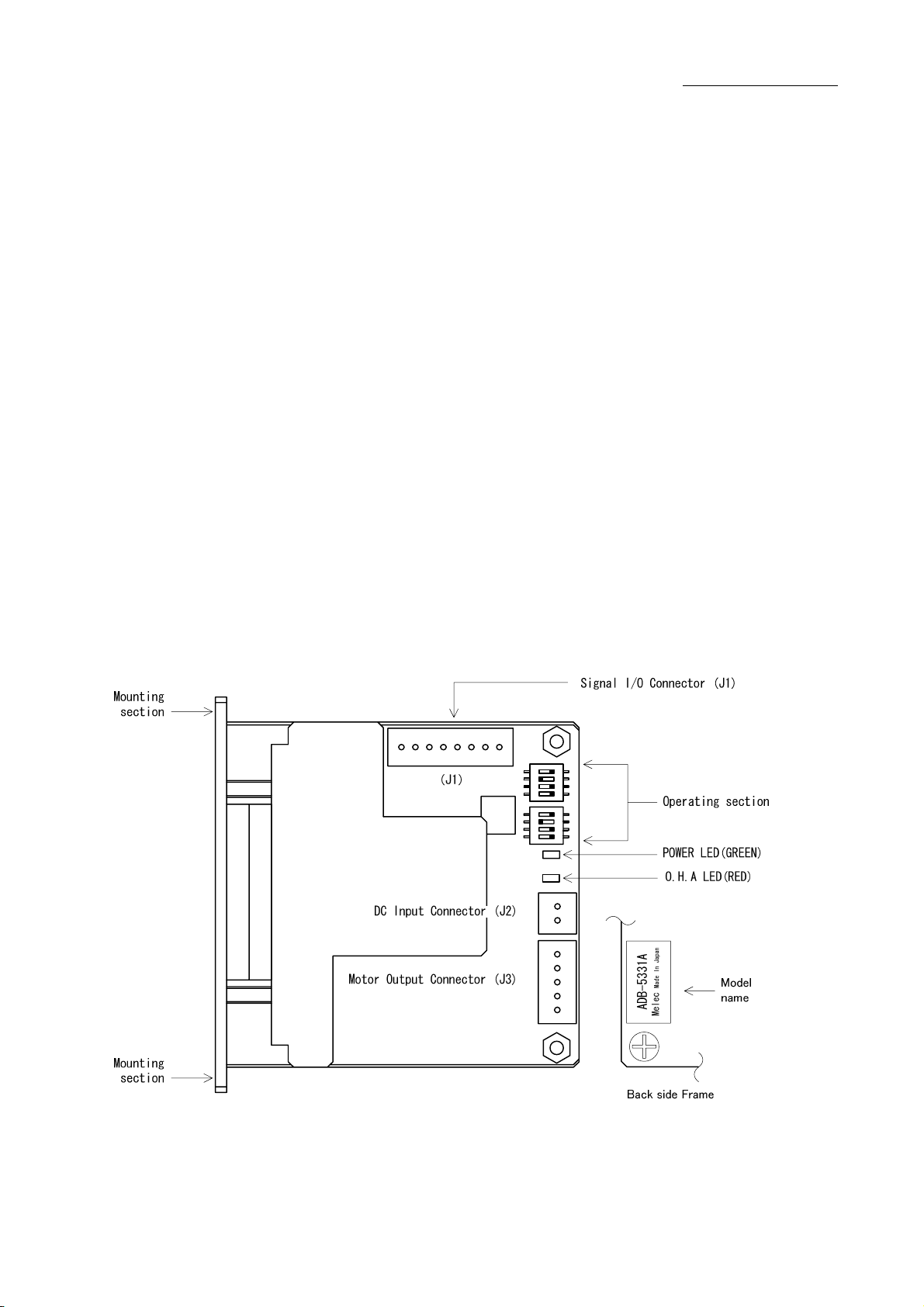
2-3.Appearance
-10-
3.Name and Function of Each Section
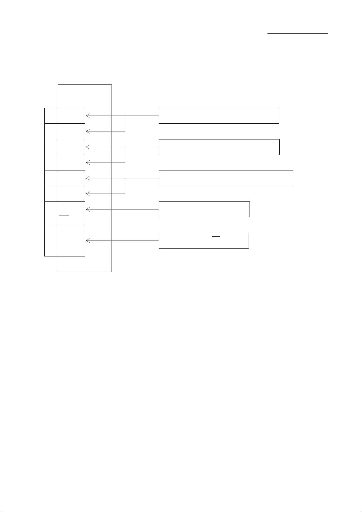
3-1.Signal I
/
O Connector(J1)
ADB-5331A
J1
CW+
●Directs the motor to operate CW.
CW-
CCW+
●Directs the motor to operate CCW.
CCW-
M.F+
●Shuts off output current to drive the motor.
M.F-
P.O ●Outputs the signal when the motor-excitation
state is the excitation home position.
R.GND
8
7
6
5
4
3
2
1CW drive pulse signal input terminal
CCW drive pulse signal input terminal
Motor excitation stop signal input terminal
Phase signal output terminal
GND terminal for P.O signal.
-11-

3-2.DC Input
/
Motor Output Connector(J2,J3)
ADB-5331A
●Power input terminal.
J3 DC power supply is connected.
●Outputs current to drive the motor.
3-3.POWER LED
POWER LED(GREEN) comes on upon inputting power.
3-4.O.H.A LED
O.H.A LED(RED)comes on when internal temperature
of the driver has reached approx. 70℃ or more.
J2
0V DC- 2
DC+24V DC+ 1
GRN BLU 5
BRN
ORN 3
YLW
WHT YLW 4
ORN
BLK
VIO BLK 1
BLU
RED RED 2
GRY
Motor output terminal
DC input terminal
-12-
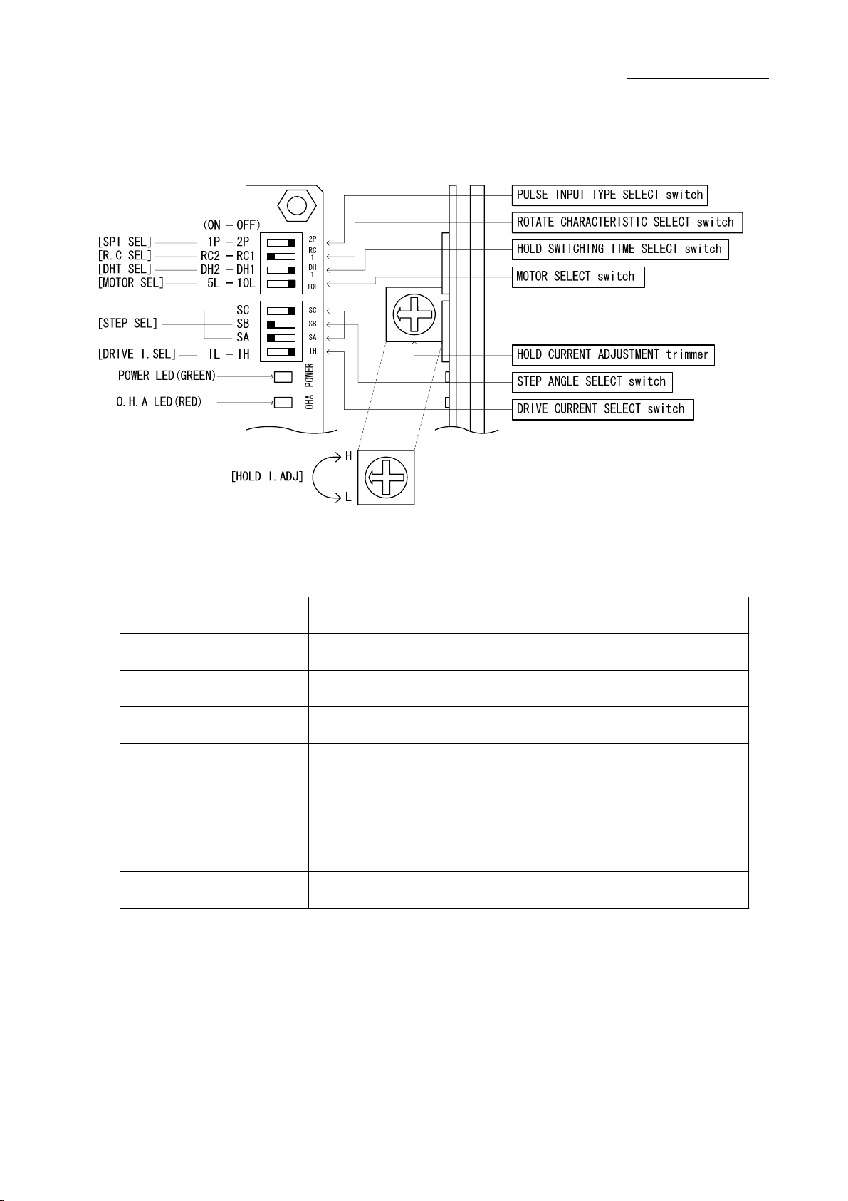
3-5.Operation Section
ADB-5331A
Name of Operation Section Function Factory
Setting
HOLD SWITCHING TIME
SELECT switch
DRIVE/HOLD CURRENT automatic switching time
is selected. 〔DH1(150ms)〕
PULSE INPUT TYPE
SELECT switch
ROTATE CHARACTERISTIC
SELECT switch Selects a characteristic of motor rotation. 〔RC2〕
HOLD CURRENT
ADJUSTMENT trimmer Adjusts HOLD CURRENT. 〔Approx. 40%〕
DRIVE CURRENT
SELECT switch Selects DRIVE CURRENT. 〔IH〕
MOTOR
SELECT switch Selects the applicable motor. 〔10L〕
SA:〔ON〕
STEP ANGLE
SELECT switch Selects a step angle. SB:〔ON〕
〔2P〕 Selects a pulse input type.
SC:〔OFF〕
-13-
4.Function Set-up by Use
4-1.Setting MOTOR SELECT switch
Erroneous setting may cause burn on the
skin due to overheating of the motor.
Ensure correct setting.
The MOTOR SEL switch is turned to the setting
corresponding to the motor in use.
Set this switch with power OFF.
The switch is factory-set to [10L].
(1) Turn power [OFF].
(2) Turn switch [10L/5L] to the setting specified in the table "10-5. Applicable Motors."
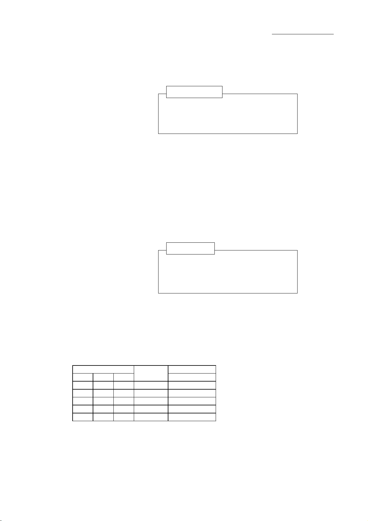
4-2.Setting STEP ANGLE SELECT switch
Erroneous setting may cause breakage of
the machine or injury due to unexpected
rotation of motor.
Ensure correct setting.
The step angle is set up with the STEP SEL switch.
The step angle can be selected from five different
types of step angles.
The switches are factory-set to [1/20 divisions].
(2) Set the STEP SEL switch [SA,SB,SC] to the step angle required.
●Relationship between the STEP SEL switch and the step angle.
(Factory setting)
OFF
OFF
ONOFF
ON
ON
ON
ON
ON
ON
SB
Number of
Divisions
Step angle(°)
0.72°motor
STEP SEL switch
SC SA
OFF
ON
0.18
0.072
0.036
1/10
1/20
ON
OFF
ON 1/4
0.72
0.36
1/1
1/2
-14-

4-3.Setting HOLD CURRENT ADJUSTMENT trimmer R1
A high setting value may cause burn on the
skin due to overheating of the motor.
Do not select a high value beyond the
required.
HOLD CURRENT is set up with the HOLD I.ADJ trimmer.
This sets the ratio of HOLD CURRENT to DRIVE CURRENT.
The trimmer is factory-set to approx. 40%.
(1) Set the gauge of the trimmer to the required value.
●Relationship between the trimmer scales and HOLD CURRENT.
HOLD CURRENT
DRIVE CURRENT
Ratio of HOLD CURRENT (typical)
Trimmer
Scale of the trimmer
● HOLD CURRENT changes relative to DRIVE CURRENT setting.
The ratio of HOLD CURRENT of 100% represents the same as the setting for
DRIVE CURRENT.
● The greater the ratio of HOLD CURRENT grows, the more heat the motor
generates when is on holding-state.
● When the trimmer is set minimum, HOLD CURRENT is approx. 20% or less of
DRIVE CURRENT.
Ratio of HOLD CURRENT(%)= ×100
100%
50%
0%
02346 89715 10
Factory Setting
-15-

4-4.Setting DRIVE CURRENT SELECT switch
Erroneous setting may cause burn on the
skin due to overheating of the motor.
Ensure correct setting.
DRIVE CURRENT is set up with the DRIVE I.SEL switch.
The switch is factory-set to [IH].
(1) Set the DRIVE I.SEL switch [IH/IL] to the setting specified in the table
"10-5. Applicable Motors."
-16-

4-5.Setting PULSE INPUT TYPE SELECT switch
Erroneous setting may cause breakage of
the machine or injury due to unexpected
rotation of motor.
Ensure correct setting.
2-pulse input method/1-pulse input method are
set up by the PULSE INPUT TYPE SELECT switch.
Set this switch with power OFF.
The switch is factory-set to 2-pulse input method[2P].
(1) Turn power [OFF].
(2) Set the SPI SEL [2P/1P] switch.
●When the motor is operated with two pulse signal inputs of CW and CCW,
switch the SPI SEL to [OFF(2P)].
●When the motor is operated with the pulse signal and direction signal
input, switch SPI SEL to [ON(1P)].
● In the case that 1-pulse input method is selected, the CCW terminal becomes
direction signal input designating the direction of the motor rotation.
Drive pulse set to the CW terminal(CW+,CW-).
● The input timing is same with 2-pulse input method and 1-pulse input method .
As for input timing, please refer to "10-2. (2)Drive pulse input(CW, CCW)"
SPI SEL
ON
OFF
Input type
1PULSE (1P)
2PULSE (2P)
CCW terminal(CCW+,CCW-)
direction set
Photo-coupler OFF: CCW direction
Photo-coupler ON : CW direction
-17-

4-6.Setting HOLD SWITCHING TIME SELECT switch
DRIVE/HOLD CURRENT automatic switching time is set up
with the HOLD SWITCHING TIME SELECT switch.
The switch is factory-set to [DH1(150ms)].
(1) Set the DHT SEL [DH1/DH2].
4-7.Setting ROTATE CHARACTERISTIC SELECT switch
The switch is factory-set to [RC2].
By setting the switch to [RC1] the vibration of the motor in
a acceleration/deceleration drive may reduce.
Select it after evaluated characteristic with an actual device.
OFF DH1(150ms)
DHT SEL Hold Switching
Time
ON DH2(15ms)
-18-

5.
I
nsta
ll
at
i
on
5-1.Conditions for Installation
Overheating may cause fire.
Mount it on a noncombustible member.
Keep it away from combustibles.
(1) Designed for incorporating into equipment used indoors, this product requires
to be installed in the following environment:
●Indoors (where it is not exposed to direct sun).
●Where ambient temperature and humidity are controlled within the range set
out in the specifications.
●Where there is no corrosive or inflammable gas.
●Where it can be protected from dust, salt or iron powder.
●Where the product main frame is not exposed to direct vibration or shock.
●Where it is not exposed to splashes of water, oil or chemicals.
(2) Install the driver at least 15mm away from other equipment.
(3) Considering heat release, control the ambient temperature around the driver
within the specified value.
●
Take measures against accumulation of heat such as allowing generous space
around the driver or installing a fan so that heat release is taken care of.
●
Install the driver securely in contact with metal or other substance with
adequate heat conductivity.
(4) In the case that an overheat alarm(O.H.A) LED comes on, perform the cooling measure
of the mounting plate is enlarged or compulsion air cooling etc.
Use the driver on the condition that an overheat alarm(O.H.A) LED goes out.
(5) Do not allow standing or placing anything heavy on the product.
15mm or more
15mm or more
15mm or more
ADB-5331A ADB-5331A
15mm or more
-19-
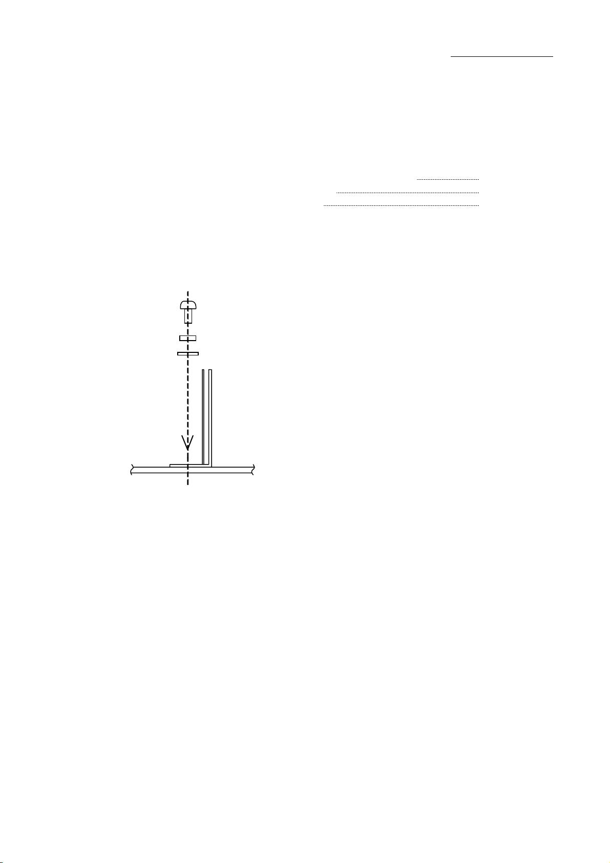
5-2.Mounting Method
The round holes on the main body are used.
The following items are required:
(1) Fix the product at the two round holes on the main body.
●Mounting example
ADB-5331A
Fixing with a screw x 2
M-3 spring washer
M-3 flat washer
M-3 screw
2●M-3 screw (8mm or more in length):
2
2
●M-3 spring washer:
●M-3 flat washer:
-20-
Table of contents
Other M-Elec Industrial Equipment manuals

Popular Industrial Equipment manuals by other brands


MachineryHouse
MachineryHouse SIEG SUPER X3 instruction manual

Rittal
Rittal R8-I operating instructions

Endress+Hauser
Endress+Hauser Silopilot FMM50 Brief operating instructions

ETC
ETC M-138 Operation and maintenance manual

Axi
Axi MTC HC-50 Installation, operating and maintenance manual

ESAB
ESAB GASARC GPE 400 Series Installation & operating instructions


