Fokker DVIII 55” Page 5
Copyright© 2006-11 M. K. Bengtson All Rights Reserved Rev 07/11
reinforcing hubs are provided that are to slip over the brass
tubing as shown. Next, CA glue the neoprene cording together to
from a “tire”. Use thin CA sparingly as the CA bonds very
aggressively to the rubber. Press the CA wetted ends together for
an instant bond. The best way to align the ends is to glue them
while they are in place on the wheel. Then attach the tires to the
wheels and CA in place. A thin bead of CA around the rim makes
for a secure tire.
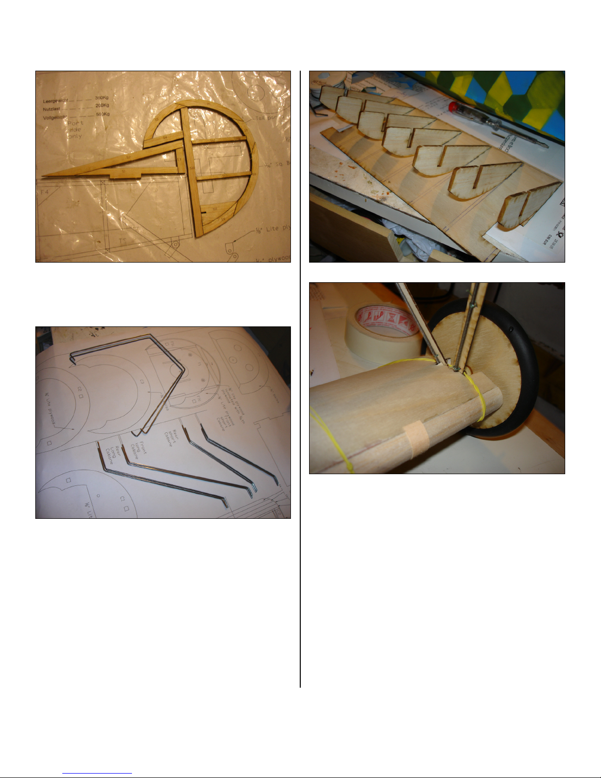
Wheel Hubs
Paper cones are cut out. Use a ball point pen to score each line
on the back to make an impression of “spokes” It is helpful to do
this operation on a paper tablet so that the pen makes a good
crease. Fold the paper along the crease lines to exaggerate the
raised lines. One of the sections forming a wedge is cut out.
Make cuts to the center of the circle along a pair of the spokes.
Close the paper cut-out to form a cone and tape the joint inside
the cone.
The inside cones may now be attached to the wheels. The
outside cones may be attached at this point if wheel collars are to
be used. Alternatively, after installing the wheels on the landing
gear, a washer may be soldered to hold the wheel in place and
then the cone is attached. This method makes a very nice scale
appearance.
INSTALLING THE RADIO CONTROL GEAR
Aileron Servos
Aileron servos are mounted in wing and attached with short
threaded rods to the ailerons. Use a “Y” wiring harness connector
to wire the servos to a single radio connection. (If differential
aileron throws are desired, rotate each servo horn forward about
20 degrees, while maintaining the neutral position of the aileron.
This should counter any adverse aileron yaw.)
Battery Tray
After all the above has been placed, mount the battery tray made
from 1/8” balsa and use the battery position to balance the model
as shown on the plan.
ASSEMBLY
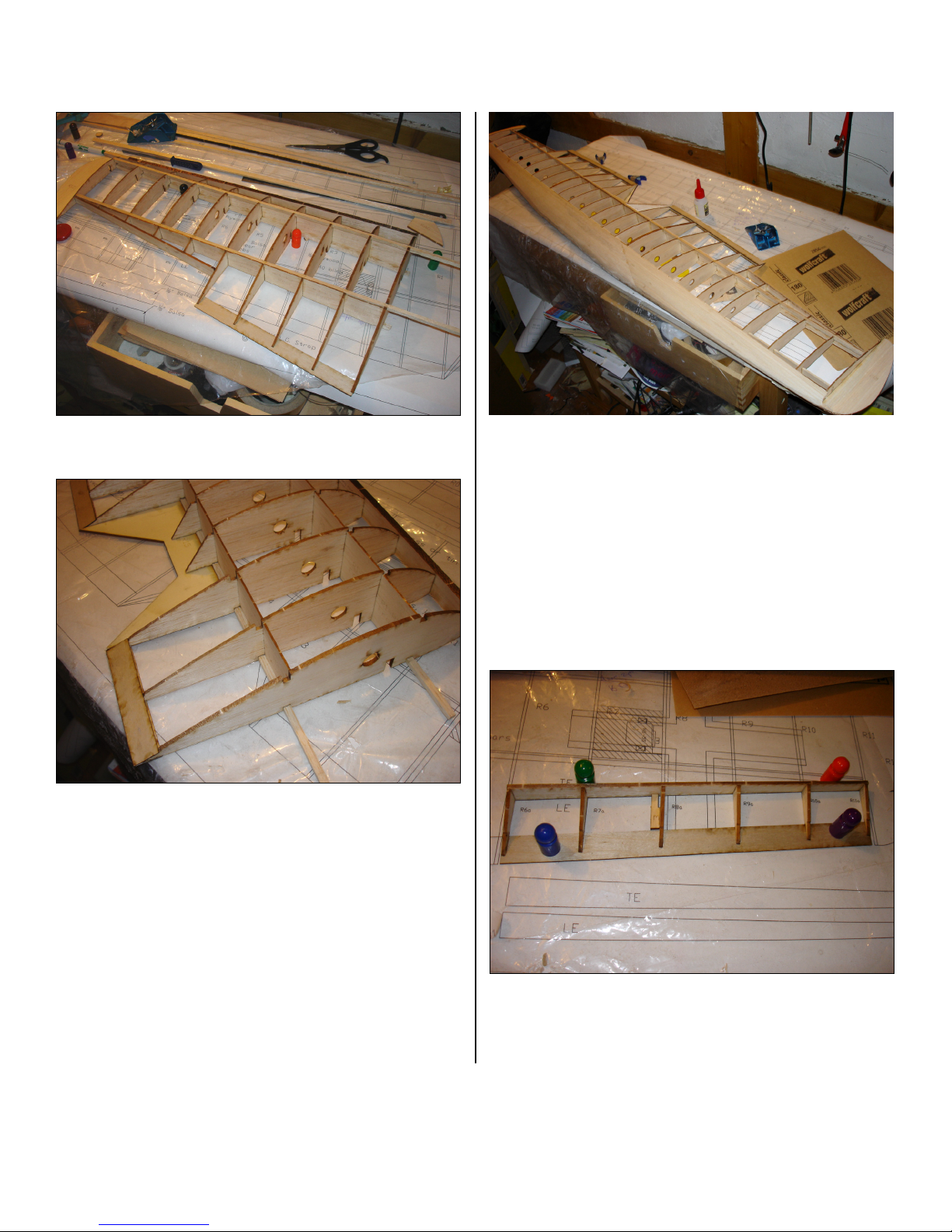
Wing
The wing is attached to the fuselage through the cabane struts.
These are made from 1/16” music wire and are formed using the
markings on the plan as a guide. Saddle clamp style straps are
used to serve as attachment points. They can be commercial
products or made from scrap tin or brass.
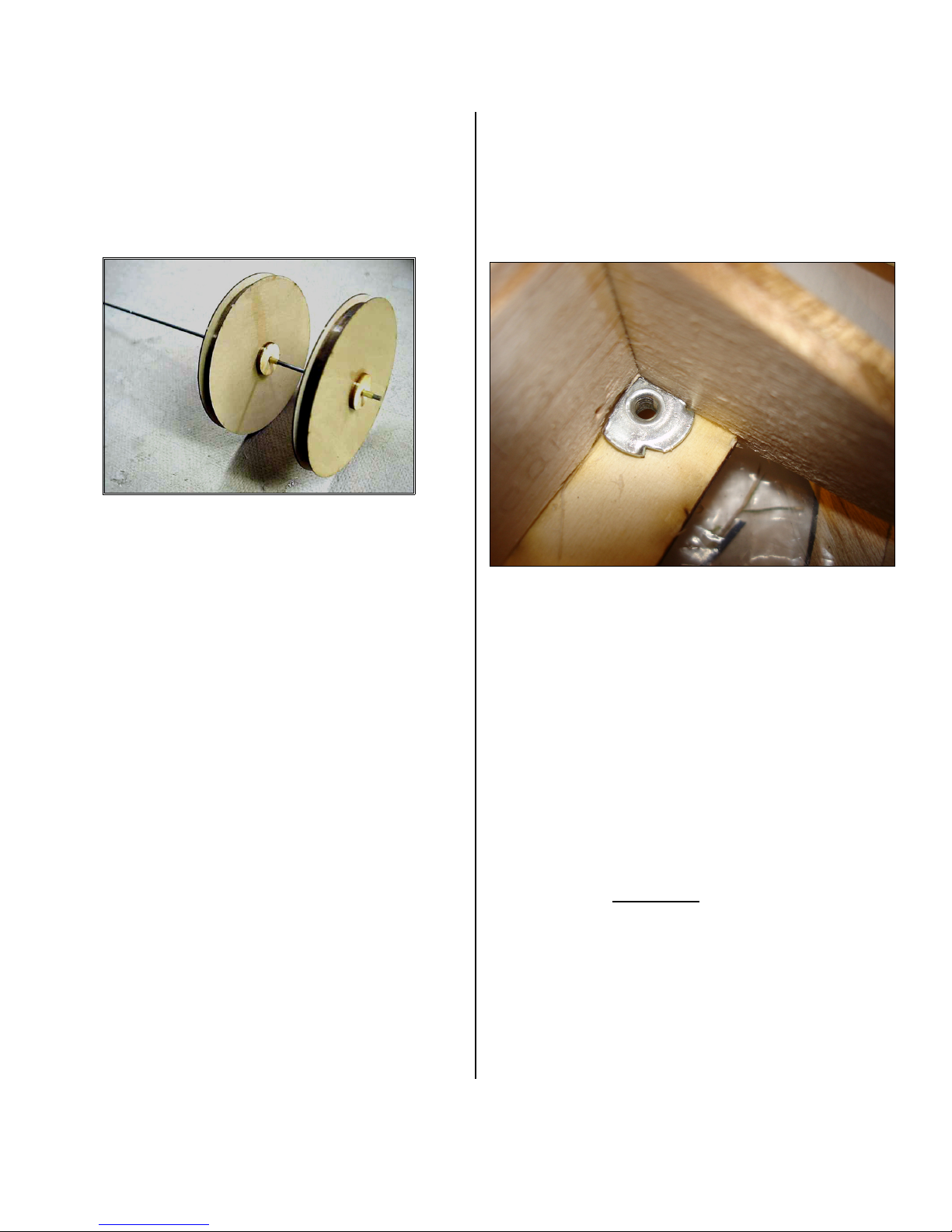
Use 4-40 bolts to secure the wing into the blind nuts embedded in
the ply mounts inside the wing.
Wing Attachment Construction Detail
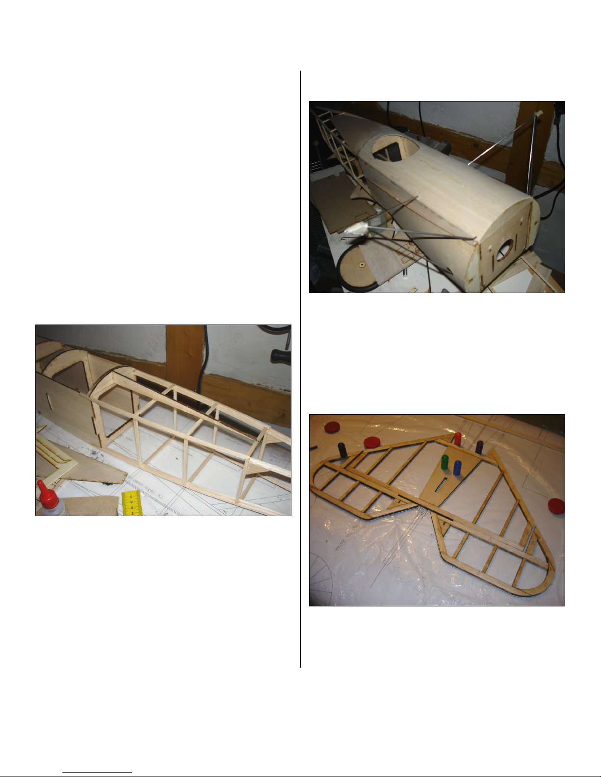
Fitting Tail Surfaces
Attach the elevator to the horizontal stabilizer.
The horizontal stabilizer and elevator are glued onto the fuselage
first and then the rudder. The rudder should be securely attached
to the fuselage as the area is relatively small. Pinning CA hinges
is recommended.
Adding Control Horns On The Pushrod Ends
Slip the control horns onto the wire pushrod ends and, with both
the servos and the control surfaces centered, glue the horns into
their slots. Some prefer to delay adding the rudder until the
elevator control horn is secure. Then add the rudder and it's
control horn. It makes the job a bit easier.
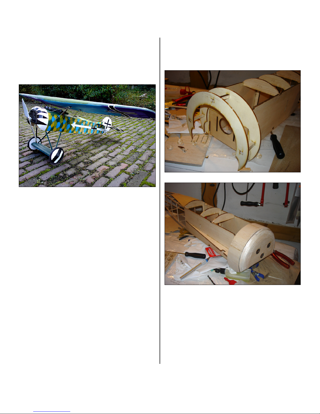
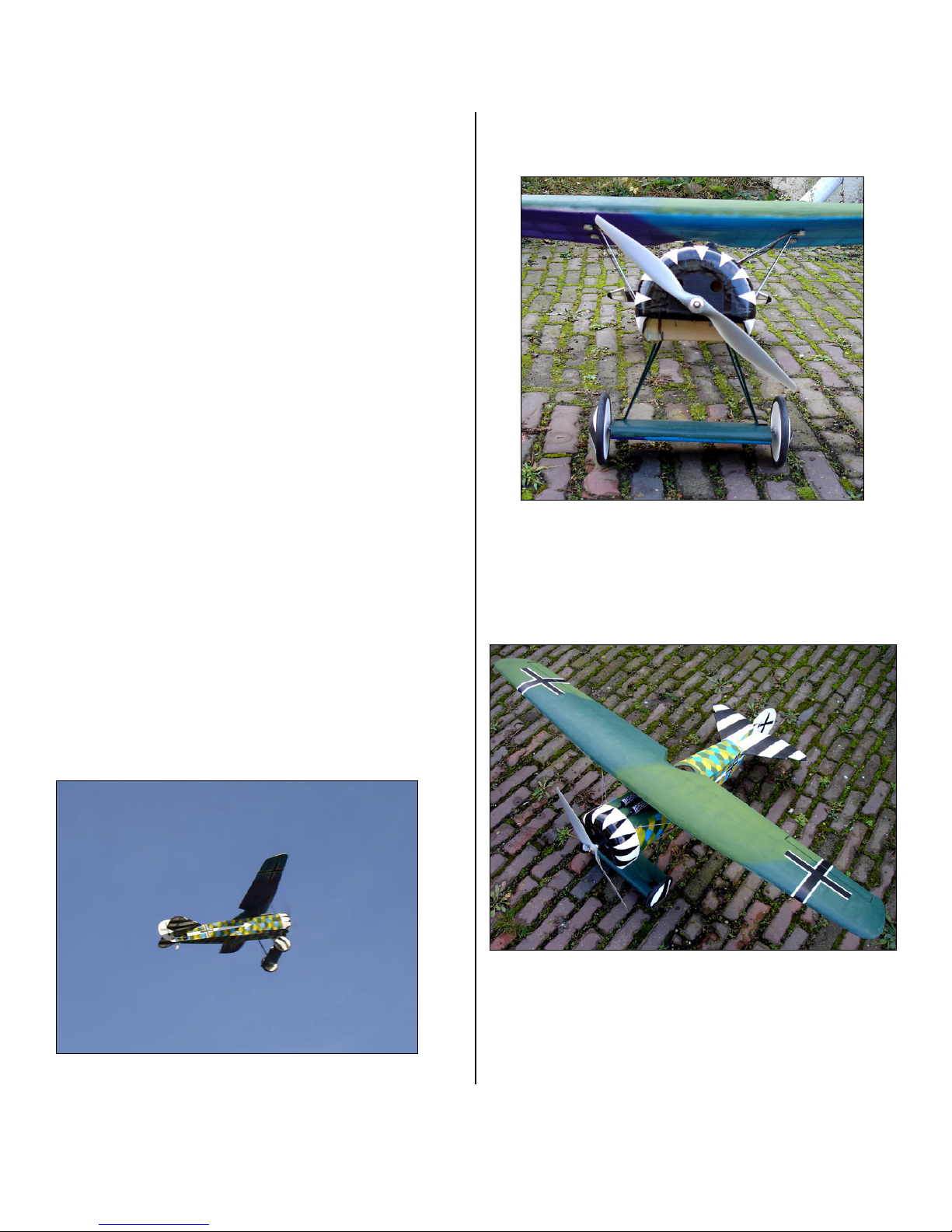
Use 4-40 bolts to attach the cowl to the firewall 4-40 blind nuts.
Windsock Datafiles “Fokker DVIII“ publication has details on
placement and markings. Available at
http://www.aeroplanebooks.com/
Battery hatch
The 1/32” plywood battery hatch is covered in covering material
after 1/8” sq. balsa reinforcement strips are attached.
Balsa Pilot figure
Assemble fill with foam and paint