M-Power PMP2RS 04 Series User manual
1
1.800.338.7337 / www.soundosignal.com
mPOWER Spoiler BRKT_Tahoe 2021 - English 1220
NOTICE:
Installers and users must comply with all applicable federal, state and local laws regarding use and installation of warning devices.
Improper use or installation may void warranty coverage.
To review our Limited Warranty Statement & Return Policy for this or any SoundO Signal product, visit our website at www.soundosignal.com/tech-services/returns/.
If you have questions regarding this product, contact Technical Services, Monday - Friday, 8 a.m. to 5 p.m. ET at 1.800.338.7337 (press #4).
Questions or comments that do not require immediate attention may be emailed to techservices@soundosignal.com.
ENHANCING SAFETY THROUGH INNOVATION
2021 CHEVROLET TAHOE SPOILER BRACKET
•HIGH CURRENT interconnects must be properly terminated. Poor crimp quality can cause heat build-up and
re. Follow crimp connector manufacturer instructions.
•DO NOT install this product or route any wires in the Air Bag Deployment Zone. Refer to vehicle Owner’s
Manual for deployment zones.
•Do NOT use system to disconnect headlights, brake lights or other safety equipment.
•Unit may become hot to touch during normal operation.
•Failure to properly install connectors, fuses or wiring may cause vehicle failure or re.
•Installation must only be performed by trained technician. Installer must determine vehicle wiring
conguration and proper integration of system.
•Use proper wire gauge. All power wires connecting to positive (+) or negative (-) battery terminal or local
chassis ground (-) must be sized to supply at least 125% of max. current and properly fused at power source.
•Install protective grommets when routing wire through rewall or metal.
WARNING
FEATURES:
• Warning arrow greatly reduces install time through use of 3-wire
technology
• Functionality mimics the rear of a lightbar
• Integrates under the spoiler of the vehicle for a seamless look
• Available in single, dual or tricolor
PART NUMBERS:
• PMP2RS104: Rear Spoiler Bracket, 1 Module Kit, Black, for use with
mpower 4” Fascia Stud Mount Light – Chevrolet Tahoe 2021
• PMP2RS204: Rear Spoiler Bracket, 2 Module Kit, Black, for use with
mpower 4” Fascia Stud Mount Light – Chevrolet Tahoe 2021
• PMP2RS304: Rear Spoiler Bracket, 3 Module Kit, Black, for use with
mpower 4” Fascia Stud Mount Light – Chevrolet Tahoe 2021
• PMP2RS404: Rear Spoiler Bracket, 4 Module Kit, Black, for use with
mpower 4” Fascia Stud Mount Light – Chevrolet Tahoe 2021
COMPONENT
QUANTITY
PMP2RS104
PMP2RS204
PMP2RS304
PMP2RS404
2021 Chevrolet Tahoe Left Bracket 1 1 1 1
2021 Chevrolet Tahoe Right Bracket 1 1 1 1
6-32 Rubber Insert 4 4 6 6
6-32 X 3/4” Allen Screw 4 4 6 6
Installation Instruction Sheet 1 1 1 1
Product Warning Card 1 1 1 1
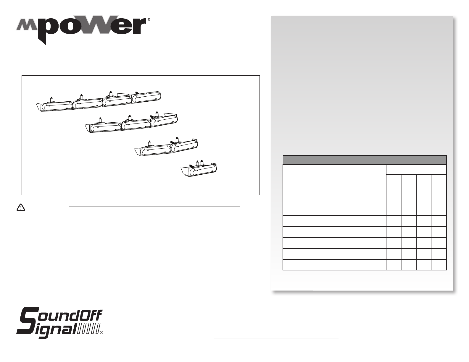
4 MODULE
3 MODULE
2 MODULE
1 MODULE
DRIVER’S SIDE SHOWN
PMP2RS(X)04 - For use with 4“ mpower fascia Stud Mount Light
2
1.800.338.7337 / www.soundosignal.com
mPOWER Spoiler BRKT_Tahoe 2021 - English 1220
NOTICE:
Installers and users must comply with all applicable federal, state and local laws regarding use and installation of warning devices.
Improper use or installation may void warranty coverage.
To review our Limited Warranty Statement & Return Policy for this or any SoundO Signal product, visit our website at www.soundosignal.com/tech-services/returns/.
If you have questions regarding this product, contact Technical Services, Monday - Friday, 8 a.m. to 5 p.m. ET at 1.800.338.7337 (press #4).
Questions or comments that do not require immediate attention may be emailed to techservices@soundosignal.com.
ENHANCING SAFETY THROUGH INNOVATION
2021 CHEVROLET TAHOE SPOILER BRACKET
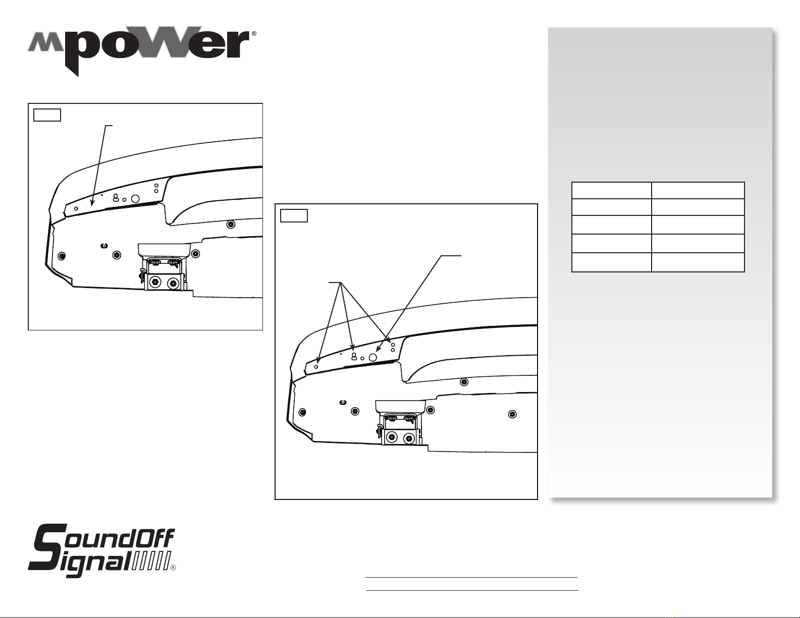
Fig. 2
INSTALLATION:
1. Remove rear spoiler from the vehicle using the
manufacturer’s recommended method. Lay the
included drill template onto the driver’s side of the
spoiler, as shown in Fig. 1. Line up the template
with the seam on the outer edge of the spoiler to
properly position it.
2. Secure the template in place with non-marking
tape.
3. Refer to the chart below and to the included
template for drill instructions:
4. Scribe the drill locations indicated by the template,
remove the template, and drill, as shown in Fig. 2.
Fig. 1
DRILL TEMPLATE
BRACKET TYPE MOUNTING HOLES
1 MODULE E, F
2 MODULE A, D
3 MODULE A, C, G
4 MODULE A, B, H
4 MODULE VERSION SHOWN
5/16” drill through rst
wall of spoiler for rubber
inserts, number of holes
is dependent on number
of modules
3/4” drill through rst
wall of spoiler for
wire pass through
DRIVER’S SIDE SHOWN
DRIVER’S SIDE SHOWN

3
1.800.338.7337 / www.soundosignal.com
mPOWER Spoiler BRKT_Tahoe 2021 - English 1220
NOTICE:
Installers and users must comply with all applicable federal, state and local laws regarding use and installation of warning devices.
Improper use or installation may void warranty coverage.
To review our Limited Warranty Statement & Return Policy for this or any SoundO Signal product, visit our website at www.soundosignal.com/tech-services/returns/.
If you have questions regarding this product, contact Technical Services, Monday - Friday, 8 a.m. to 5 p.m. ET at 1.800.338.7337 (press #4).
Questions or comments that do not require immediate attention may be emailed to techservices@soundosignal.com.
ENHANCING SAFETY THROUGH INNOVATION
2021 CHEVROLET TAHOE SPOILER BRACKET
INSTALLATION (CONT).:
5. Flip the drill template over and lay on passenger’s
side. Temporarily, secure in place with non-
marking tape. Scribe the drill locations indicated
by the template.
6. Remove the template and drill as indicated.
7. Attach the lights to the included brackets, as
shown in Fig. 3. Secure nuts 1/8” turn past seated
contact.
8. Press the 6-32 rubber inserts into the spoiler. Then
place the bracket, as shown in Fig. 4. Route wires
through the wire pass through hole. Secure with
screws supplied. Hand tighten using a 5/64” ball
end hex key. Repeat for opposite side.
9. Drill a hole in the desired location in the hatch
sheet metal, if necessary.
10. Run the wires through the hole.
11. Before re-installing the rear spoiler, make all
electrical connections. Refer to the mpower arrow
kit instruction sheets for details.
12. Reassemble spoiler assembly according to
manufacturer’s specications.
13. Test to ensure proper functionality.
Fig. 3
Fig. 4
Ifacongured,mpower® ArrowKitwas
purchased,skiptoStep8.
4 MODULE VERSION SHOWN
4 MODULE VERSION SHOWN
NOTE:Ifawireroutecanbeidentiedinthe
rearhatchspoilerandsheetmetal,skipto
step11.
PRO TIP: Agrommetisnotincludedbut
recommendedtoprotectthewirefrom
sharpedges.Sizetheholefordesired
grommetsize.
This manual suits for next models
4
Table of contents
Other M-Power Automobile Accessories manuals


