manuals.online logo
Brands
  1. Home
  2. •
  3. Brands
  4. •
  5. M-system
  6. •
  7. Cables And Connectors
  8. •
  9. M-system 18KBXC-K5 User manual

M-system 18KBXC-K5 User manual

P. 1 / 3
EM-0492-K5
5-2-55, Minamitsumori, Nishinari-ku, Osaka 557-0063 JAPAN
Phone: +81(6)6659-8201 Fax: +81(6)6659-8510 E-mail: info@m-system.co.jp
18KBXC-K5
BEFORE USE ....
Thank you for choosing M-System. Before use, check the
contents of the package you received as outlined below.
If you have any problems or questions with the product,
please contact M-System's Sales Office or representatives.
n PACKAGE INCLUDES:
Standard rack...........................................................(1)
n MODEL NO.
Confirm that the model number described on the product is
exactly what you ordered.
n INSTRUCTION MANUAL
This manual describes necessary points of caution when you
use this product, installation, connection and basic mainte-
nance procedures.
POINTS OF CAUTION
n POWER INPUT RATING & OPERATIONAL RANGE
24 V DC ±10%, 2.5 A minimum
n ENVIRONMENT
• When heavy dust or metal particles are present in the
air, install the unit inside proper housing with sufficient
ventilation.
• Do not install the unit where it is subjected to continuous
vibration. Do not apply physical impact to the unit.
• Environmental temperature must be within -5 to +55°C
(23 to 131°F) with relative humidity within 30 to 90% RH in
order to ensure adequate life span and operation.
• Be sure that the ventilation slits are not covered with
cables, etc.
n WIRING
• Do not install cables (power supply, input and output) close
to noise sources (relay drive cable, high frequency line, etc.).
• Do not bind these cables together with those in which noises
are present. Do not install them in the same duct.
n AND ....
• The unit is designed to function as soon as power is supplied,
however, a warm up for 10 minutes is required for satisfying
complete performance described in the data sheet.
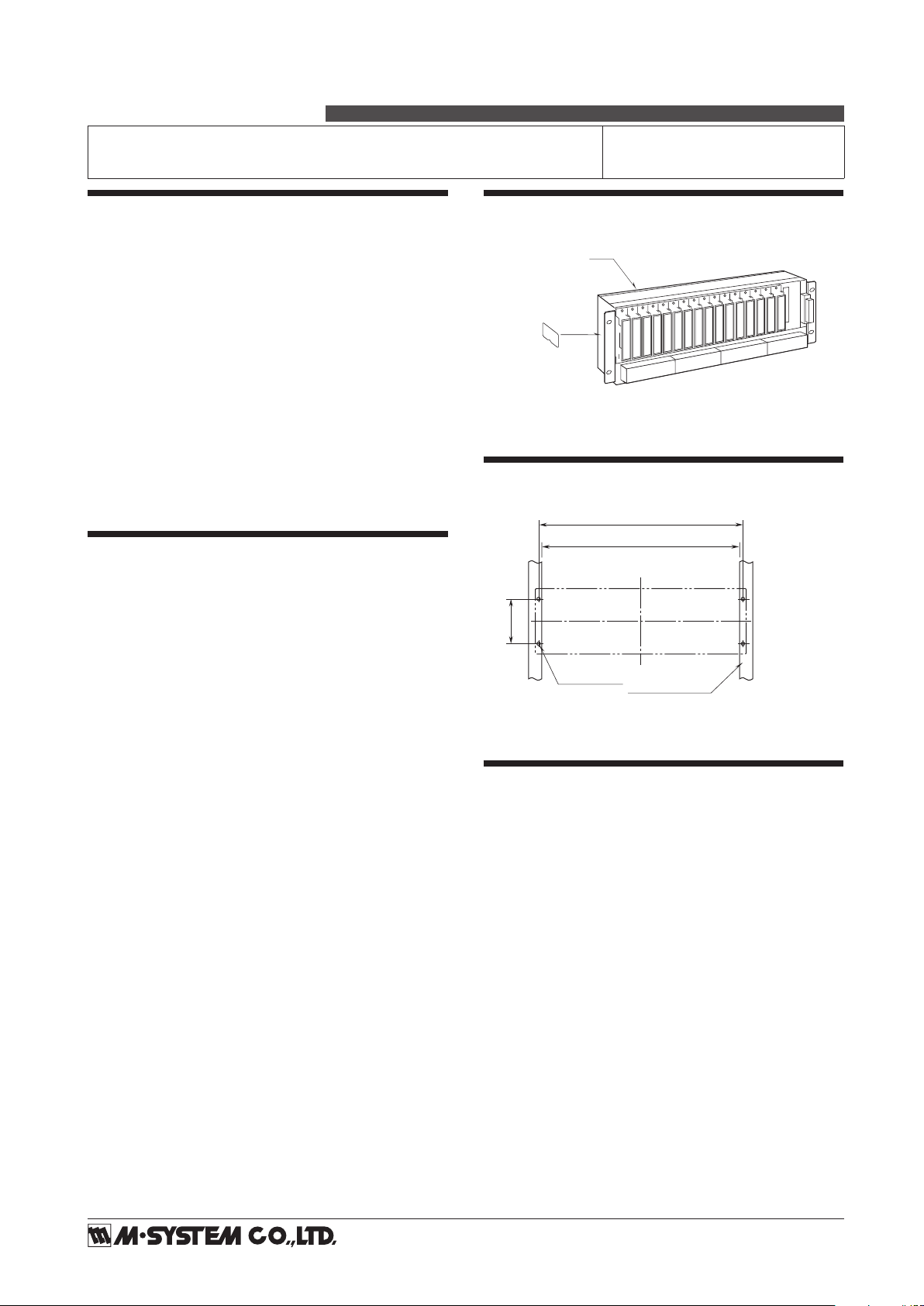
COMPONENT IDENTIFICATION
Specifications
(Side)
Body
MOUNTING REQUIREMENTS mm (inch)
101.6
(4.00)
*
450 (17.72)
465 (18.31)
4–M5 SCREW ANGLE BRACKET
Observe an appropriate wiring space over and below.
*
100 (3.94)
for JIS standard
CHECKING
1) Terminal wiring: Check that all cables are correctly con-
nected according to the connection diagram.
2) Power input voltage: Check voltage across terminals 1
(+) – 2 (–). Use a power source of ripple level 10% p-p or
less.
3) Installation & environment: Check ambient temperature.
Also check that there are no excessive dust particles around.
Check that there is no vibration.
STANDARD RACK
(Yamatake DCS PI connector) MODEL
18KBXC-K
5
INSTRUCTION MANUAL
P. 2 / 3
EM-0492-K5
5-2-55, Minamitsumori, Nishinari-ku, Osaka 557-0063 JAPAN
Phone: +81(6)6659-8201 Fax: +81(6)6659-8510 E-mail: info@m-system.co.jp
18KBXC-K5
TERMINAL CONNECTIONS
Connect the unit as in the diagram below.
nEXTERNAL DIMENSIONS mm (inch)
nCONNECTION DIAGRAM
1
2
FG
3
CN1
CN2
+
−
POWER
FIELD TERMINALS
13 1521416 1514 16
2
1
3
+
+
96 (3.78)
38 (1.50)
2 (.08)
435 (17.13)
134 (5.28)
2 (.08)
■RACK (standard) ■SURFACE (option /W)
465 (18.31)
480 (18.90)
CN2
CN1
1357911 13 15246810 12 14 16
150 (5.91)
101.6 (4.00)
8.5 (.33)
3-M4 POWER TERMINAL
8.2 (.32)
64−M3.5
FIELD TERMINAL*
121 2 12
343 4 34
1ch 15ch 16ch
*Field I/O Terminal Block
P. 3 / 3
EM-0492-K5
5-2-55, Minamitsumori, Nishinari-ku, Osaka 557-0063 JAPAN
Phone: +81(6)6659-8201 Fax: +81(6)6659-8510 E-mail: info@m-system.co.jp
18KBXC-K5
nCONNECTOR PIN ASSIGNMENT
Location
Output connector: 57LE-40500-7300
CN1, CN2: PI use
18K-RACK LOCATION NO.
123456789
10 11 12 13 14 15 16
1234567812345678
YAMATAKE DCS PI CARD
(J-PIM00) INPUT
Connector Pin Assignment (CN1, CN2)
PIN NO.
(CN1)
ASSIGNMENT
PIN NO.
(CN2)
ASSIGNMENT
3ch. 1 + 3 ch. 9 +
4 ch. 1 – 4 ch. 9 –
5ch. 2 + 5 ch.10 +
6 ch. 2 – 6 ch.10 –
7ch. 3 + 7 ch.11 +
8 ch. 3 – 8 ch.11 –
9ch. 4 + 9 ch.12 +
10 ch. 4 – 10 ch.12 –
27 ch. 5 + 27 ch.13 +
26 ch. 5 – 26 ch.13 –
29 ch. 6 + 29 ch.14 +
28 ch. 6 – 28 ch.14 –
31 ch. 7 + 31 ch.15 +
30 ch. 7 – 30 ch.15 –
33 ch. 8 + 33 ch.16 +
32 ch. 8 – 32 ch.16 –
11 – 25 and 50 (CN1, CN2): Unused
1, 36, 38, 39, 41, 42, 43 and 45 in CN1 and CN2 are connected.
The output 1 is connected to the connector.
YAMATAKE DCS PI CARD
(J-PIM00) INPUT
CN1 CN2
2, 34, 35, 37, 40, 44, 46 and 47 in CN1 and CN2 are connected.
48 and 49 in CN1 and CN2 are connected.

Other M-system Cables And Connectors manuals

M-system MCN201 User manual

M-system

M-system MCN201 User manual

M-system M8BS-16U2 User manual

M-system

M-system M8BS-16U2 User manual

Popular Cables And Connectors manuals by other brands

Atim Cloud Wireless ACW/LW8-DINRSM user guide

Atim Cloud Wireless

Atim Cloud Wireless ACW/LW8-DINRSM user guide

CMP C2K installation instructions

CMP

CMP C2K installation instructions

Philips SWV3103W Specifications

Philips

Philips SWV3103W Specifications

CYP CH-526RXPL Operation manual

CYP

CYP CH-526RXPL Operation manual

Goobay 68876 manual

Goobay

Goobay 68876 manual

HQ AVSPLIT-25 manual

HQ

HQ AVSPLIT-25 manual

Goobay 56589 user manual

Goobay

Goobay 56589 user manual

Stahl SolCineX Plug operating instructions

Stahl

Stahl SolCineX Plug operating instructions

LAPP EPIC H-D 7 Assembly instruction

LAPP

LAPP EPIC H-D 7 Assembly instruction

AAVARA PS124 installation guide

AAVARA

AAVARA PS124 installation guide

Eaton COOPER POWER SERIES Assembly/installation instructions

Eaton

Eaton COOPER POWER SERIES Assembly/installation instructions

Euvision Split 16 4x4 Service notes

Euvision

Euvision Split 16 4x4 Service notes

Playvision HBT-914H100 user guide

Playvision

Playvision HBT-914H100 user guide

Spector SPECTECH NATHAN T997 user manual

Spector

Spector SPECTECH NATHAN T997 user manual

Wayne-Dalton 3995 installation instructions

Wayne-Dalton

Wayne-Dalton 3995 installation instructions

ODU MINI-SNAP K Series manual

ODU

ODU MINI-SNAP K Series manual

Camille Bauer PRKAB 560 operating instructions

Camille Bauer

Camille Bauer PRKAB 560 operating instructions

Siemens 3VA957-0JB23 Series operating instructions

Siemens

Siemens 3VA957-0JB23 Series operating instructions

manuals.online logo
manuals.online logoBrands
  • About & Mission
  • Contact us
  • Privacy Policy
  • Terms and Conditions

Copyright 2025 Manuals.Online. All Rights Reserved.