Maber MB500/120-SP Instructions for use

1
RACK AND PINION HOIST
MABER
ONE-PHASE
INSTRUCTION AND MAINTENANCE MANUAL
THIS MANUAL IS AN INTEGRATED PART OF THE MACHINE
IMPORTANTE WARNING:
This instruction manual should be completely read carefully before putting the equipement to
use; all the assembly instructions, the use and maintenance must be precisely
precluded to unauthorized personnel.
MABER costruzioni srl
36050 Bressanvido (VI) Italy via S. Benedetto, 14/P z.a.
Telefono: +39-0444-660871 Fax: +39-0444-660872
14/09/98 –libretto uso manutenzione MB500/120 - SP
COPY

2
PREFACE
This manual is supplied along with the sold machine and contains guidelines for its
transportation, assembly, operation and maintenance, as specified in the guidelines outlined
in the EU 89/392 Machine directive.
CONTENTS
List of sections and paragraphs with page references:
* Analytical index page 38
1. CE declaration of Compliance “ 03
2. Machine identification “ 04
3. Description of the machine “ 05
4. Machine application “ 07
Unauthorised uses of lift “ 08
5. Guarantee “ 09
6. How to consult the manual “ 09
7. Technical description “ 10
8. Specifications “ 12
9. Safety regulations “ 13
10. Machine transportation “ 14
11. Packaging “ 14
12. Loading/unloading support “ 15
13. Installation “ 16
14. Assembling the vertical column “ 18
14a. Emergency brake test “ 19
15. Standard wall mounting “ 22
15a. Special wall mounting “ 23
16. Trial before use “ 24
Machine operation:
17. Machine controls page 24
18. Checks and tips before use “ 25
19. Operator’s guide “ 25
20. Start-up “ 26
21. Setting the machine up for idling “ 26
22. Adjustments and regulations “ 27
Maintenance:
23. Periodic maintenance page 28
24. Non-routine maintenance “ 29
25. Technical support service “ 30
26. Maintenance schedule “ 30
27. Lubricants “ 31
28. Electrical diagram “ 32
29. Failures “ 33
30. Spare parts (legend) “ 35
Spare parts diagram “ 36
31. Disposing of the machine “ 37
Employment and intructions of the safety landing gate page 39
Technical Drawings page 48
COPY

3
1. “CE” DECLARATION OF COMPLIANCE
This declaration issued by the manufacturer must be stamped and signed
by the same and stored with the original machine documentation.
MABER Costruzioni s.r.l.
whose legal head office is in 35014 Fontaniva - Padova - Italy - Via Casoni Basse, 16
and whose offices and plant are in Via S. Benedetto, 14/P - 36050 Bressanvido -
VICENZA - (ITALY)
in the capacity of the manufacturer of the machine concerned identified as:
model: MB 500/120 SP serial N°:_______________ year of manufacture:____________
max. height 120 m max. load 300 kg
confirms
that it complies to the safety regulations specified in the health and safety regulations and
guidelines as defined in enclosure N° 01 of:
Machine directive 98/37/E.E.C., Section V
including all supplementary guidelines.
The planning refers, when it is possible, at the following rules:
DPR 27.04.55 n° 547
DPR 07.01.56 n° 164
CNR-UNI 10011/88
The technical documentation with enclosure N° 05 of the EU is available from the
manufacturer.
The trial conducted on ___________ had a positive result.
The machine serial plate is printed with the initials of the Inspector:
(B.L.) Bertoncello Luciano.
The inspector is responsible.
Inspector’s signature MABER Costruzioni s.r.l.
__________________ ________________________
COPY

4
2. MACHINE IDENTIFICATION
The equipment of which to the present manual is identified by the following elements, that
which must be cited with a request for additional information of replacement:
MANUFACTURER: MABER Costruzioni s.r.l. Via S.Benedetto, 14/P
36050 Bressanvido VICENZA (ITALY)
CLIENT: CITY/TOWN:
MACHINE: RACK AND PINION ELEVATOR
MODEL: MB 500/120 SP
MAX. LOAD: 300 Kg
MAX. HEIGHT: 120 m.
POWER SUPPLY VOLTAGE: ONE PHASE 220/50 Hz
YEAR OF MANUFACTURE:
SERIAL NUMBER :
DELIVERY DATE:
EXPIRY DATE OF THE GUARANTEE (12 MONTHS):
AREA AGENT:
AFTER SALE SERVICE:
The identification data are printed on a special plate attached directly to the machine in the
position shown in the diagram below:
Important: Do not use the machine without its identification plate.
COPY

5
3. DESCRIPTION OF THE MACHINE
The MB 500/120 SP RACK AND PINION HOIST is a goods lift that allows elevation up to
120 m. in height, along the support column, anchored to a wall or scaffolds designed to bear
loads transmitted up to a max. load. of 300 kg.
The lift is basically made up of the following parts:
x A base fitted with adjustable worm screws.
x A vertical column (fitted with a rack), composed of modular latticed elements, that must
be joined every 6 m. to a wall or a support frame.
x An loading deck driven by an electric motor via a rack and pinion coupling.
x A series of securing bolts let the frame be held vertically (every 6m.).
x A series of safety devices.
COPY

6
The drawing illustrates the standard basic version of the machine:
The machine is fitted with a separate centrifugal-mechanical emergency brake
(patented) that automatically starts up if the descent speed exceeds approx. 20% of the
normal preset values. The device enables a ratchet gear that allows the deck to stop in a
damped and gradual way at any point of the vertical column.
The machine in question has been produced to comply with the regulations mentioned in the
declaration of compliance attached to this manual and subjected a trial as is stated in the
declaration itself (see page 3).
COPY

7
4. MACHINE APPLICATION
The MB 500/120 SP RACK AND PINION HOIST must be used only to lift goods and
equipment up to a maximum loaded weight evenly distributed on the deck of 300 kg.
The equipment may be only used for professional purposes by personnel authorised
by the owner over 18 years of age and who have been previously trained in
compliance with the regulations and guidelines of this manual.
The lift must be used only:
xAfter correctly installing the base on a stable and adequately strong support
surface (see page 16),
x After correctly installing the vertical columns and securing bolts on the wall as required by
specifications,
x After checking the safety devices and accesses to the various storeys,
x After checking the emergency brake works properly.
x In winds up to maximum speed of 70 km/hour.
x In ambient temperatures ranging between -15° and +45° C.
Persons may only be carried during the assembly and disassembly stages, by carefully
following all safety regulations.
The diagram illustrates the loading conditions that must always be heeded:
YES NO
MAXIMUM LOAD 300 KG.
Place goods as near as possible to the vertical column.
Fasten the material adequately.
Do not use the MB 500/120 RACK AND PINION HOIST when
COPY

8
In MB 500/120 RACK AND PINION HOIST operation any misuse of the equipment is not
allowed. This particularly includes:
- carrying persons and animals,
- carrying protruding loads,
- carrying goods that have not been properly tied,
- carrying loose goods,
- Operation in harsh weather conditions (thunder storms, wind, snow etc.)
- Operation in conditions of poor visibility (fog, night darkness etc..)
- Operation in wind speeds over 40 km/hour when assembling the rack
- Operation in wind speeds over 70 km/hour when using the rack
- Operation in very harsh temperatures or with ice that might
stop the ratchet gear of the emergency brake,
DO NOT USE - Operation at ambient temperatures over +45°,
- Operation at ambient temperatures below -15°,
- Machine operation without terminal switches,
- Operation without periodic maintenance,
- Operation when the column has not been firmly secured,
- Operation after tampering or modification unauthorised
by the manufacturer,
- Use of unoriginal spare parts,
- Machine operation in explosive environments
- Use when submerged in liquids,
- Use near free flames.
!!! CAUTION !!!
In all cases in which the lift cannot be used the deck must be lowered to ground level
and the machine must be set up for idling, as described in the relevant paragraph.
NO NO
5. GUARANTEE
COPY

9
The manufacturer’s guarantee is valid for 12 months after the delivery date of the
equipment and is limited to the replacement of parts that are to the incontrovertible
judgement of the manufacturer defective due to materials used or to manufacturing .
La guarantee is always and only valid for goods delivered ex works and any other kinds of
compensation, besides the description in the above point, are not considered.
The guarantee is not valid and the manufacturer can be exempted from any responsibility if:
xThe user tampers, without prior written authorisation from the manufacturer, with any
parts or accessories of the appliance itself,
x Damage is caused by misuse of the equipment or by failure to comply with the operating
regulations and guidelines,
x Damage is caused by neglecting to apply the maintenance instructions.
x Operation is contrary to specific directives,
x It has been badly installed,
x electric power supply failures occur,
x The instructions given are not heeded even in part.
x Replacement of any parts or components must always be previously authorised by the
manufacturer.
The guarantee does not cover the electric parts of the machine.
The law court of PADOVA ITALY is responsible for any litigation.
6. HOW TO CONSULT THE MANUAL
The operating and maintenance manual is an integral part of the machine.
Before commencing any installation jobs and machine operation the operator must
carefully read the text with particular regard to all operational safety regulations and
guidelines.
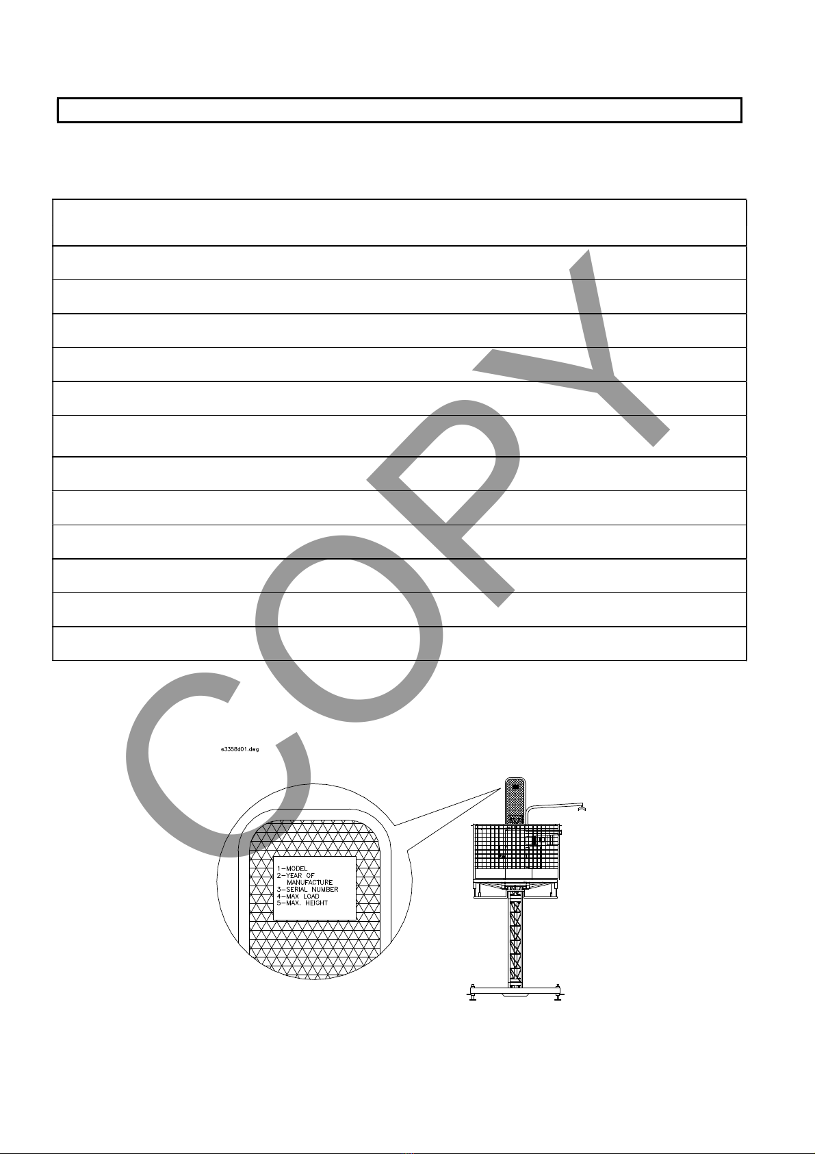
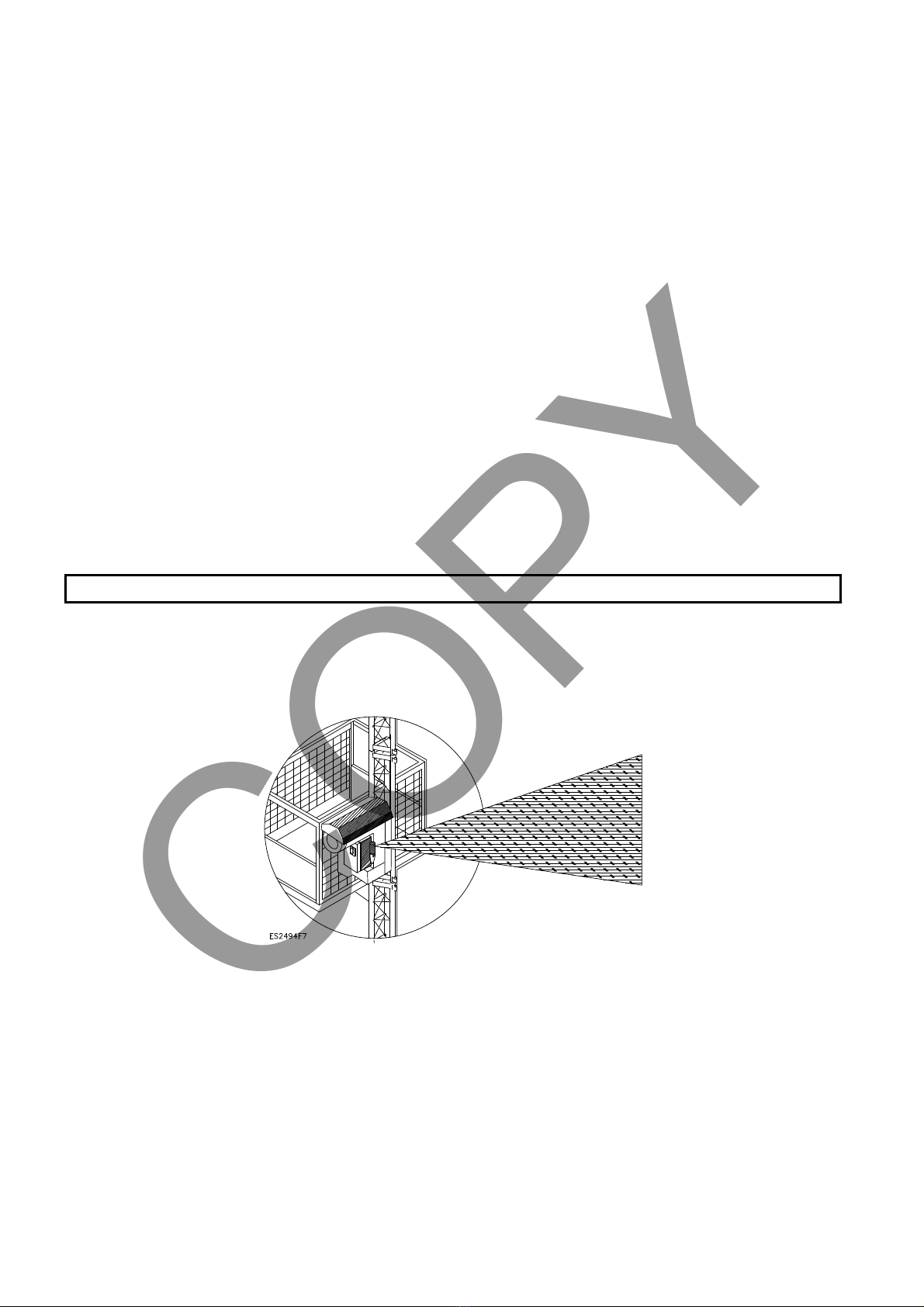
This manual (or an integral copy of it) must always be on the machine so that the
operator can immediately consult it at any time. The drawing above shows where the
manual should be placed inside the sealed box of the electric board. Owing to the
constant and continuous improvements made by manufacturer to the product, the supplied
machine might differ in some technical details from that described in this manual. However,
any variation is always accompanied by specific enclosed documents illustrating functionality
and features. Should there be any discrepancies compared to the content of the handbook,
the user may immediately ask for supplementary technical data sheets.
COPY

10
7. TECHNICAL DESCRIPTION
The MB 500/120 RACK AND PINION HOIST is a machine designed to elevates goods
up to 300 kg. A motor-powered moving deck slides on a special vertical column up
to 120 m in height. The vertical column is attached to the wall or support frame every 6m.
The base (1) is made up of a welded tubular frame, at the end of which 4 worm screws (2)
are installed to regulate vertical alignment of the machine.
The vertical column (3) 1.50 m. in length, is made with latticed and welded tubular bars
and a rack. It must be bolted with appropriate securing bolts (4) every 6 m. to a support
wall or a frame able to bear the transmitted loads indicated in paragraph 15 on page 22.
The loading deck (5) consists of a welded sheet walkway on a support frame made of
section bars. The walkway is limited by a pair of fixed guards (6) along the longer sides
and two access gates are provided on the shorter sides equipped with tilting bar (7) and
lower walkway (8) that can be let down. As soon as the latter is opened, the lift is
automatically locked.
To prevent accidental dropping on people or goods a gridiron guard (9) is installed to stop
machine movement when it touches a foreign body.
Key to drawing
1. base
2. worm screws
3. vertical column
4. wall mounting
5. loading deck
6. guards
7. upper bar
8. loading ramp
9. gridiron guard
10. turning plate
COPY

11
The motor drive unit (11) is made up of a welded tubular bar and section bar frame. It is
fitted with a series of guide rollers. It is driven by a self-acting electric gear motor (12) that
enmeshes on the rack of the vertical column (3) via a pinion,.
An emergency brake (14) starts when (in descent) the normal operating speed is
exceeded. A special ratchet gear for centrifugal force expands and activates the brake. If
the brake is enabled, a special terminal switch stops movement.
The electric power for the gear motor is supplied via a power supply cable and controls
(15). To prevent the cable interfering with the machinery, special cable clamps (16) must
be attached every 9 m. (In windy areas at least every 6 m). The cable is gathered in a
special container (17) placed on the base.
To make easier the loading and unloading of the deck, two ramps (8) are lowered to form
a support deck. When the ramps are opened and closed, the movement of the lift is
stopped. The lift movement is controlled via a suspended control panel (18) that is
located to the ground or directly connected to the electric board during the assembly and
disassembly stages of the column.
Moreover, the loading deck can be turned by 90
degrees, which allows getting closer the scaffolding or
building. If the deck is not properly closed, a
purposely-designed terminal switch stops any
movement.
Key to drawing:
11.Motor drive unit
12.Self-acting electric
gear motor
13.gridiron guard
14.emergency brake
15.power supply cable
16.cable clamp
17.cable container
18.control panel
COPY

12
8. SPECIFICATIONS
Working capacity on the storey (evenly distributed load) 300 kg.
Max. height of the vertical column: 120 m.
Lifting speed: 20 m/min.
Height of the vertical column modules: 1.5 m/each
Weight of the vertical column modules: 33 kg/each
Max. vertical distance of the wall securing bolts: 6 m.
Height from ground of the temporary assembly and disassembly bolt: 2 m.
Deck width: 1.5 m.
Deck length: 1.3 m.
Weight of the complete unit (deck at base): 440 kg.
Guard height: 1 m.
Height of the loading deck from ground (at bottom terminal switch): 0.25 m.
Three-phase electric power supply. 230/50 Hz
Voltage for low tension controls: 48 Volts
Electric gear motor power: 2.5 kW
Input current while working: 18 A
Rack module: 5 mm.
Lifting pinion teeth: N° of teeth 20
Emergency brake pinion teeth: “ “ 18
Outer diameter of the guide and sliding rollers: 48 mm.
COPY

13
9. SAFETY REGULATIONS
The MB 500/120 SP RACK AND PINION HOIST has been designed and produced in
compliance with the current safety regulations.
The user has to heed all safety regulations required for the type of equipment used,
the work environment and the effective operating conditions, for him/herself and for
other working in the vicinity.
The equipment may only be used if the following safety regulations are heeded:
x The base must be installed on a sufficiently strong support surface according to the
loads indicated on page 16.
x The whole ground area of the equipment must be adequately cordoned off and
signposted.
x Access to the operating area must be reserved only to operators.
x Install the special signs: “suspended loads - no access and thoroughfare - danger of
falling objects - safety helmet must be worn - etc..-”
x Operators must wear a safety helmet.
x Connect the electric power line with the earth wire.
x Check the stability of the wall on which the vertical column is to be mounted (loads
applicable as per diagrams given on page 22).
x Check that the accesses to the loading / unloading decks are adequately cordoned off
and that these barriers can be removed only after the lift has reached its height and are
compulsorily refitted when the lift is not on the storey.
xThe machinery assembly and disassembly workers must be supplied with a
safety belt.
xDo not assemble the machinery if the wind speed exceeds 40 km/hour.
xDo not use the lift if the wind speed exceeds 70 km/hour. In this case the deck
must be returned to the ground.
NB: Benchmark wind speed according to C.N.R.10012/85, ground roughness: cat.3-4.
MAIN SAFETY DEVICES:
The machine is fitted with the following safety devices:
x Down terminal switch
x Up terminal switch
x Deck turning closing control sensor
x Vertical column guard closing control sensor
x Loading ramp closing control sensor
x Emergency brake enabling control sensor
x Storey stop control sensor
x Up and down over-limit switch
x Damped bottom buffers
x Self-acting gear motor
x Centrifugal mechanical brake with damped stop
x Non-skid gridiron (located under the loading deck)
The lift can also be lowered even when there is no power supply, by operating the release
lever of the motor brake (see relevant section).
COPY

14
10. MACHINE TRANSPORTATION
The machine is delivered completely assembled (base, initial column, loading deck) and
equipped with fittings, fixed to pallets with metal straps; a set of modular elements of the
column is packed under the base, on the same pallet.
The other modular elements of the column are packaged (approx. 30 pieces) on another
pallet.
The pallets must be unloaded and handled by a forklift truck (min. required capacity
1000 kg. with protrusion of approx. 1.20 m).
Should machine be moved with a crane or another hook lifting tool, insert the hook
only in the column flange plates as shown in the figure below.
11. PACKAGING
The machine is packaged and fastened with a metal strap. The electric parts and most
delicate components can be protected with a plastic sheet until delivery
Take off the plastic sheet, if present, and make sure that it is not within children’s
reach. Remove the packaging only using the containers provided for refuse collection.
Remove the metal fasteners, discard them only after winding and dispose of them
properly.
Make sure that the machine has not been damaged before delivery. If it has, immediately
inform the salesperson or manufacturer before using the machine.
Check that the moving parts of the machine are fitted (adjusting screws, nuts and bolts,
ramps, guards, electric system etc..) and comply with supply specifications.
Check for any discrepancies compared to the ordered equipment. If there are any, always
advise the dealer or manufacturer before use.
COPY

15
12. LOADING - UNLOADING SUPPORT
To make easier the loading or unloading of the lift on motor vehicles, some
detachable supports can be optionally requested, which allows the operation to be
carried out without using any other lifting devices.
Two uprights (1), 1 left-hand cross-piece and 1 right-hand cross-piece (2-3) are
required. Before starting any operation, unload any vertical column (with the exception of
the one fixed to the base).
A. Loading the machine on a vehicle:
x connect the machine to the supply mains (following the instructions detailed above).
x move the deck up to about 1 m. using the control panel.
x insert the left-hand cross-piece (2) in the upright (1) and lock it at the height required
using the pegs supplied. The same applies to the right-hand cross-piece (3).
x fit the two units in the relevant tubes (4) welded at the bottom of the lift deck.
x lower the deck so that the uprights (1) touch the ground, the base is thus lifted. Follow
this procedure to reach the height required.
x place the vehicle under the lift base.
x start raising. The deck will now lower to allow the base to rest on the vehicle platform.
Continue this operation until the uprights (1) can be removed. Disconnect the mains
supply and fasten the machine for transport.
B. Unloading the machine from the vehicle:
x connect the machine to the supply mains.
x follow the instructions detailed in “A” in reverse order.
Key to drawing:
1. Upright for loading-
unloading support
2. Left-hand cross-piece
for loading-unloading
support
3. Right-hand cross-piece
for loading-unloading
support
4. Tubes to be inserted
COPY

16
13. INSTALLATION
The lift must be installed only by skilled workers authorised for operation.
The machine must be installed on a floor able to bear the following loads relative to the
height of the vertical column
Column
height
Machine
weight
Working
capacity
Total
load
m. Kg. Kg. Kg.
1,5 440 300 740
25 1090 300 1395
50 1740 300 2040
75 2390 300 2690
100 3040 300 3340
120 3560 300 4860
Lay underneath the support worm screws some shimming
plates compatible with the total applied load.
The placement area must comply with the following minimum
dimensions, to allow access around the machine for the
various installation and operation jobs.
To assemble the machine use a pair of 24 mm. hexagonal
wrenches..
After the above check, install the machine strictly
following the guidelines below:
x Lay the base on the ground.
x Check that its distance from the wall is regular
matching the type of bolting supplied (minimum
distance 50 cm).
x Use a spirit level to check the horizontal alignment of
the base and the vertical alignment of the column.
Make the necessary adjustments with the 4 lateral
adjusting screws (1). After levelling, lock the screws
with their ring nuts (2).
x Make sure that the screws (4) of the vertical column on
the base (1) are firmly tightened. Otherwise tighten
them properly.
x Check the access ramps (8) and the access closing
arms (9) work regularly.
x Swivel the cable-guide arm (10) to its regular position
and lock it.
x Fit the 2nd column (11) and lock it with the screws
provided.
COPY

17
Caution: Regular tightening of the 4 vertical column
screws ensure the necessary operating machine stability.
Periodically check they are tightened.
Only use class 8.8 (12) screws.
x Check the vertical alignment of the column again in both
directions and make the necessary corrections by always
turning the worm screws on the base, and finally clamping
after the operation.
Before connecting the machine to the
electric power line make sure that:
1. The line is regularly “earthed” and is fitted
with a differential cutout switch (0.3)
2. The power supply matches the machine
voltage.
3. The power supply cable is of the right
width.
4. The earth wire of the machine has been
connected.
x About 1.3 m. above the ground attach the
first cable-guide arm (1) and fix it with a
clamp.
x Place the box (2) of the electric power
supply cable (3) to ensure that it is
regularly unwound and rewound during
up and down movements.
x Plug the machine into the electric power
line by inserting the plug (4).
x Couple the connector (5) of the control
board (8). Test movement by enabling the
control buttons: line, up down, emergency
stop.
x Should the control not coincide with the
motor phases a special device prevents
any movement. The phase inverter (6)
fitted on the door lock mechanism of the
control panel box (7) needs then to be
operated.
x Then enable ascent. A safety device,
proximity switch, stops the vertical
column motor unit from going off course.
The lift is ready for installation of the
following vertical columns.
COPY

18
14. ASSEMBLING THE VERTICAL COLUMN
After installing the base of the lift, the modular elements of the column can now be
assembled. For this purpose two operators may board the lift and operate as described in
this section.
!!! WARNING!!! While assembling the machine, never turn the deck, and keep it in
the locked position.
The deck can be turned only after the column has been fastened to the wall through
the clamps, as shown in sections 15 and 15a.
x Make sure the installation procedure described above has
been followed.
!!! CAUTION!!! In case of an emergency that requires
the machine to be stopped immediately, press the red
STOP button located on the control board..
x Get onto the deck: by lifting the traverse bars that must
then be closed again and locked using the relevant
locking pegs.
!!! CAUTION!!! The vertical column, for safety purposes,
must always be assembled (and disassembled) on the
deck by TWO AUTHORISED WORKERS wearing a
safety helmet and quick coupling safety belt
x Deck operation is allowed only when the guard (1) is
closed (vertical position).
x Load the 1st vertical column on the deck, lower the guard (1). Fit and connect the 1st
vertical column with the screws provided. Close securely.
x Alight and fit, 2 m. above the ground, the 1st securing bolt (temporary safety bolt for
assembly and disassembly).
xPress the emergency “stop” button to stop any movement.
CAUTION: A photocell control unit built into the motor drive unit automatically
stops the lift near the end of the column.
If stopped, only the deck down movement remains activated.
CAUTION: In case of accidental opening, stops due to collisions etc. all stoppers for
sensor activation automatically cut off the electric power supply. To restore power
subsequently, the green start button mounted on the control board needs to be
pressed.
!!! CAUTION !!! If the nuts and bolts of the vertical column
are not tightened this might cause it to overturn.
1. Refit and clamp the guard (1) to reactivate line authorisation.
2. Load 2 vertical columns and 1 complete securing bolt on the
deck.
3. Release movement by turning the “stop” button. The press
Start.
4. Then assemble the vertical columns and the first securing
bolt that must be fitted 6m. above the ground..
5. Restart descent down to the ground and leave the deck to
conduct the braking tests on the emergency brake (see
page 19).
COPY

19
14a. !!! CAUTION - EMERGENCY BRAKE TESTS !!!
The test must be conducted about every 3 months
and/or whenever the machine is assembled by
personnel trained in compliance with the guidelines
outlined below:
To conduct the test the following conditions must be
met:
xThe machine must be firmly secured.
xThe access area under the loading deck must be
completely cleared and cordoned off to prevent
access.
xThe loading deck must be raised to a height of 3.5 m.
above the ground.
xThe machine must be unloaded.
xThe red emergency button must be pressed on the
pendant control.
To simulate the operation of the emergency brake, the
motor brake must be disabled. By disabling the brake,
the loading deck accelerates down until the emergency
brake is applied.
Therefore, this operation must be performed with
utmost care by previously trained and authorised
workers.
Take the following steps:
xTake the release lever (1) that is screwed on the
motor casing and screw it onto the nearby threaded
hole.
xConnect the lever (1) with a rope made of nylon or
similar material 6-8 mm. in diameter.
xMove about 3 m. from the loading deck and pull the
rope. This action will open the motor brake.
x At this point the machinery always descends faster until it activates the emergency
brake which must be applied 2.5 m. above the ground.. The run, from when the
emergency brakes is applied to when the machinery is definitively locked, must be
around 300 mm.
x Should the machinery not stop, immediately release the rope, to reactivate the motor
brake (that stops the machine).
x In this case, immediately contact the manufacturer or authorised dealer, since the
emergency brake operation is not regular.
x Should the test be positive, load the machine first with 150 Kg. and then with 300 Kg.
and conduct the tests as described above.
x After checking the efficiency of the emergency brake, release the emergency button,
press the start button ( so as to reactive the emergency brake), then lower the machine
to the ground pressing first the up button and immediately afterwards the down button.
x The loading deck will stop at the bottom terminal switch.
x Remove the rope. Unscrew the lever (1) and place it in the casing.
NEVER LEAVE THE RELEASE LEVER COUPLED IN THE BRAKE
Should the braking of both the motor brake and of the emergency brake be either too slow
or too sudden, the brake control must be adjusted by acting as described in the “NON-
ROUTINE MAINTENANCE” section.
COPY

20
If you are in the assembly stage, take the following steps:
CAUTION: Load at most 3 vertical column modules on the deck.
The operators on the deck must always work with their safety belt fastened to the
deck to ensure they are suspended if they slip off.
x Raise the deck up to the top limit of the pre-assembled column, lower the guard (1) and
couple the new module, making sure with
utmost care that the screws are tightened.
x To reactivate ascent, always refit the guard
(1).
x Then proceed likewise for the remaining
modules up to the desired height.
!!! CAUTION!!!
2 m. above the ground the temporary
assembly and disassembly wall bolt must
be attached by clamping it with wall plugs
or other tools as shown in the diagram on
page 22. The wall or the support scaffold
must be able to bear the transmitted loads.
Then attach the wall mounting at least
every 6 m.
x If necessary attach stroke limit stop runners
on the storey (3) so as to ensure it stops at
a preset height.
x Make sure that the storey accesses are
adequately cordoned off and fitted with
warnings on special signs attached to the
inside of the building well stating “free fall
hazard”.
x Every 9 m. (every 6 m in windy areas)
attach cable-guides (4) onto the vertical
column.
After assembling the last vertical column, fit the
up terminal switch runner. Also install the
last wall mounting even if the distance
from the previous one is less than 6m.
x After assembling the vertical column lower
the deck to ground level.
x Remove the control board coupled directly
on the control panel.
x Couple the control board onto the
connector to operate from the ground.
COPY
Table of contents
Popular Construction Equipment manuals by other brands

Dynapac
Dynapac DR7 operating instructions

Chicago Pneumatic
Chicago Pneumatic CP9620 Instruction manual/safety instruction

MAC TOOLS
MAC TOOLS EC2T owner's manual

Smiley Lifting Solutions
Smiley Lifting Solutions SPYDERCRANE PC094 Operator's manual

TSE
TSE DPT60 owner's manual

WIRTGEN
WIRTGEN W 50 instruction manual

SFS intec
SFS intec isoweld 3000 Installing instructions

SFS
SFS Dynamic 2DA Fitting and adjustment instructions

MULTIQUIP
MULTIQUIP Stow MS-63 Operation and parts manual

XPOtool
XPOtool 61031 Operation manual

RaycoWylie
RaycoWylie i4507 instruction manual

Mounting Systems
Mounting Systems Premium Series installation manual