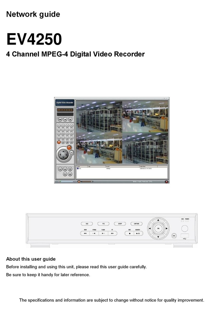
Mace DVR0414 Quick start guide

Mace Security Products, Inc. Presents:
Digital Video Recorder based on Mpeg4 Technology

2
Thanks for purchasing products of Mace Security International, Inc.
For your convenience in calling for service or technical support, please
record the following important information:
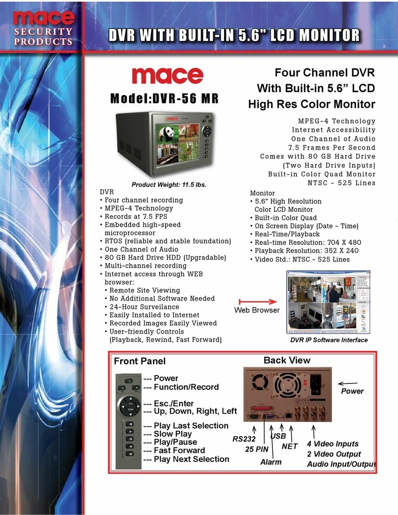
Model: DVR0414, DVR56MR, DVR15MR (select one)
Hard Disk: 80G, or __________
Serial #:
Date Purchased:
Sales Person:
Company Name:
Phone:
Fax:
Consult Mace’s website at http://www.mace.com for a complete line of
surveillance and security products.

3
General Safety Precautions
This manual applies to Mace 4-channel non-realtime series Digital Video Recorders. There are three
models in this series, DVR0414, DVR56MR, and DVR15MR. DVR0414 will be used in all illustrations.
1. Installation Environment
2. Open Product Box and Verify Contents
3. Before Power-up

4
1. Installation Environment
- An UPS (Uninterrupted Power Supply) with power surge protection is strongly
recommended for DVRs and all associated devices (routers, DSL modems, etc)
- Avoid extreme heat
- Avoid direct sunlight
- Avoid excessive humidity
- Maintain horizontal mounting
- Avoid excessive vibrations
- Do not stack other devices on top of the DVR
- Operate in well ventilated place, do not block the cooling fan
2. Open Product Box and Verify Contents
Check for the following accessories:
- One power cord
- One hard disc Ribbon Cable
- One operation manual
- One CD for utility software (normally it is not needed).
- One remote control unit
- Two AAA batteries
3. Before Power-up
- Make sure the orange tab is set to 110V at the back of the DVR power supply
- Be sure the UPS power supply is properly connected
- Be sure to plug power cord into a reliable 110 VAC power source

5
Table of Contents
General Safety Precautions ?3
1. Installation Environment ?4
2. Open Product Box and Verify Contents 4
3. Before Power-up ?4
Chapter 1: Product Specifications and Features ?7
1. Product Specification 8
2. Product Features ?9
3. Storage Matrix 11
Chapter 2: Basic System Operations ? 13
1. Start/Stop the DVR ?14
2. Recording 15
3. Alarm Input/Output ?16
4. Pan-Tilt Control 16
5. Network Operation ?16
Chapter 3: Front Panel Operations 17
1. Front Panel Overview ?18
2. Detail Key Function 19
3. Enter/Leave the Operation Menu 21
4. Maneuver in the Operation Menu ?22
5. Menu Overview 23
6. Operation Description ?27
6.1 Recording Control ?27
6.2 Playback 27
6.3 Pan-Tilt and Zoom Camera Control 29
6.4 Menu Detail 30

6
Chapter 4: Operations over Network 37
1. Setting Up the Client End ?38
2. Login and Logout ?38
3. Operation of the Right Click Menu Items ?40
4. Record Search and Playback ?43
5. System Configuration ?45
6. Assistant 50
Chapter 5: System Connections 55
1. DVR Rear View 56
2. RS-485 Port Connection ?57
Appendix 1 Frequently Asked Questions 60
Appendix 2 Hard Disk Installation ?62
LIMITED WARRANTY ?63

7
Chapter 1 Product Specifications and Features
1. Product Specifications
Product Features
Storage Matrix

8
1. Product Specifications
Parameter 4 Channel
Processor
Operation system Real-time operation system
PSOS
!#"$%$
Video input
$
Channel
&
(')(*(+(,
BNC
1.0V
P- P
-
75
./
Video output
Channel
*(+')0
BNC
1.0V
P- P
-
75
./
video signal
Audio input
Channel 200-1000mv10K
.
(RCA)
Audio output
Channel 2000mv 1K
.
(RCA)
Video display 1,4 ,5 windows display
Video standard NTSC
525 line, 60f/s
0
PAL
625 line, 50f/s
System resource Non real-time recording and simultaneous network operation, independent local playback
Image resolution Real-time monitor 704
1
576, playback 352
1
288,
Motion detection Area setting:
2(
detection areas on the screen; detection sense setting: 3 levels detection sense for
each area
Video compression MPEG-4 VBR (variable frame rate)
Audio compression
*()
Image compression rate 352
1
288CIF format
Video recording speed Total resources 25frames for PAL mode, 30 frames for NTSC mode
Image quality 6 levels selectable
Hard disk One 40G hard disk preinstalled. Expandable to two large size hard disks.
HDD space used Audio
3
14.4Mbyte/hour Video
3
60-460Mbyte/hour
Alarm input 4 channel voltage alarm input
4
5
564
15V D. C. Needed for the alarm input
Alarm output 3 channels output,
output in open/close contact or controllable
4
12V output
Alarm relay 30VDC 1A, 125VAC 0.5A
relay output
Network connection RJ45 10M/100M Ethernet connection
Pan-tilt control RS485
Power 110+15%V 60+2% HZ
Power consumption 60W
Working temperature
7
10
8974
55
8
Working humidity 10
:;7
90
:
Barometric pressure 86kpa
7
106kpa
Size 200 (breadth)x275(depth)x130mm (height)
Weight 5.5KG
9
2. Product Features
- Real-time Monitor (Video Displays)
o2 Video output ports to regular Analog Video Monitor
oSingle window (Full Screen) /4 windows (Quad) /5 windows monitor display.
- Compression Method
oMultiple video compression modes: Variable frame.
oSingle channel or 4 shared audio/video real-time recording or multi-channel non-real time
audio/video recording.
- Storage
oInternally can hold 2 IDE-compatible large capacity Hard disk(HDD)
oAlternative HDD operations that will reduce the power consumption and heat emission.
oOverwrite (FIFO) and Stop (HDD Full) modes for DVR HDD recording.
- Back-up
oUSB port for external back up of records.
oDownload the files on DVR to local PC through network.
- Play and Record
oSupports multiplexed operation: live monitor, record, search for downloading, one channel
play-back and remote transmission simultaneously.
oMultiple recording modes: Manual – Schedule – Alarm - Motion Detection. Note: Alarm
Recording and Motion Recording have Pre-Alarm function.
oPlayback: One window playback while live viewing all four channels. Playback also available
using Network Connection.
oFast search for reviewing manual recording and alarmed recording.
oMultiple play-back modes: fast forward, pause, X ?, X 1/3, X1/4 S slow play and frame by
frame playback.
oDisplays Time/Date during playback.

10
- Alarm relay
o4 channel external alarm input, video lost alarm and motion detection alarm.
oMulti channel relay switch alarm output activates alarm relay and on-site light control.
oCircuit Protection for Alarm inputs and outputs.
- Pan-tilt Control
oSupports Camera Pan-Tilt-Zoom (PTZ) Functions using RS485 Communication Protocol.
oIntegrates multiple protocols to control various PTZ speed domes.
- Communication Connection Port
oDB 15 (15 pin) connection for alarm inputs and PTZ control.
oRS232 port for the connection with keyboard for central control and matrix control.
oStandard Ethernet port for remote viewing and control.
- Network Operation
oRemote real-time monitor.
oPan-tilt-zoom control.
oRecord search and real-time playback. Note: playback quality dependent on network conditions.
Downloading records through network.
oSystem programming, settings & modification and system software upgrades available online.
oRemote alarm processing and system log review remotely.
oEmbedded TCP/IP protocol and RTOS (Real Time Operating System) supports Web server
direct connection to operate and control all the above functions.
oAdministration mode: Three USER levels for logging in remotely. Each user login is
password protected.

11
3. Storage Matrix
The HDD Capacities and Recording lengths are determined by capacity of the installed HDDs and the selected
image level.
The following storage time is based on the average use for HDD space for single channel recording.
Note: DVR0414 supports 30 frames per second recording in total for the whole machine. Users may chose to
record a single channel in real time (30 fps) or split the system resources evenly among several channels. Under
the LIMITED mode, every one of the four cameras will be recording at a fix rate of 7.5 fps. Under the AUTO
mode, depending on the number of channels that are recording, a channel can take 30, 15, 10 or 7.5 fps.
Following are storage calculation guidelines (in the number of Days):
Image
Quality 30F/S Days
80G 1(128kb/s) 128kb/s 61
2(256kb/s) 256kb/s 30
MP4(CBR) 3(384kb/s) 384kb/s 20*
4(512kb/s) 512kb/s 15
5(768kb/s) 768kb/s 10
6(1024kb/s) 1024kb/s 8
* This reads that with an 80G harddisk, at CBR (constant bit rate) 30 fps and Image Quality 3, DVR will be able
to record 20 days.
Coding Image level Resolution Frames Maximum data flux Average HDD
space
<
/hour
=
1 352*288 30 128Kb/S 40MB
2 352*288 30 256Kb/S 80MB
3 352*288 30 384Kb/S 120MB
4 352*288 30 512Kb/S 160MB
5 352*288 30 768Kb/S 240MB
CBR
6 352*288 30 1Mb/S 320MB

12
Image Quality 15F/S Days 10F/S Days 7.5F/S Days
80G 1 85kb/s 92 71kb/s 108 69kb/s 112
2 144kb/s 56 109kb/s 72 92kb/s 84
MP4(VBR) 3 158kb/s 48 133kb/s 60 114kb/s 68
4 227kb/s 36 175kb/s 44 159kb/s 48
5 292kb/s 28 258kb/s 32 200kb/s 39
6 557kb/s 16 443kb/s 18 333kb/s 24

13
Chapter 2 Basic System Operations
1. Start/Stop the DVR
Recording
Alarm Input/Output
Pan-tilt Control
Network

14
1. Start/close the recorder
>?@>
>?@>>?@>
>?@>
Start the recorder
Plug in the power line; switch on the power button at the back of the recorder; power indicator light on; DVR
on; default single window for the video output displays; press Enter the Log-in screen appears on Monitor; If
the starting time is within the programmed recording time, the system will start recording function automatically.
Channel indicator lights will indicate the cameras in record mode. The system will work in a normal manner.
Note: if the system stops during HDD Boot detection, the HDD may not be installed right and please check the
HDD connections (Ribbon and Power Connections). *Please unplug the 120VAC power supply during HDD
installation*
1.2 Enter the setting menu
Before you enter the menu, you must input the password. There are two levels of password—User password and
Administrator password.
Administrator password
AAAAAA
AAAAAAAAAAAA
AAAAAA
(Press the Jump to Next Section key 6 times)
General user password
BBBBBB
BBBBBBBBBBBB
BBBBBB
((Press the Fast Forwarder key 6 times)
If input the user password, you have to input again at the next login; you are also not allowed to enter
system setting and admin setting.
Note:
For the consideration of security, please change the Administrator password in
admin settings.
Refer to Chapter 3 Front Panel Menu Operation for details.
1.3 Turning off the DVR
Press the POWER key on the front panel for 4 seconds to stop the current operations. Then switch off the power
button at the DVR rear to turn off the power
.
1.4 Power off recovery
When the power is cut off abnormally, the recorder will recall it\s last state and continue where it left off. The
state indicator light is the same as it was before the power off
.

15
2. Recording
The default recording mode after startup of the DVR is 24 hr continuous recording for each channel. The
User can program customized recording times for each camera. Instructions for the different recording modes are
as follows:
a) Schedule Recording:
?Enter the menu, and set the timing period for the recording. See details at Menu>System setting>Schedule
b) Manual Record Selection
?Press “Record” button on the remote controller or “Rec” on the front panel.
?Check the status of each channel in the recording menu; The Highlighted channels are in record mode.
?To select the channel to be recorded, press the related number key. Selected camera # will highlight on
your screen. When all cameras that need to be recorded are selected, press Enter to begin the recording.
?Repeat above steps and remove the highlight to stop the camera from recording. ress Cancel or ESC to
return without changes.
c) Alarm recording
?Connect the alarm input according to the device connection and the instructions.
rogram the related settings in the menu to start Alarm recording. See details at Menu>System
setting>Alarm setting
d) Motion detection recording
?Record the channel only in need of motion detection. First confirm whether this channel is programmed in
Timing Recording; if it is, please turn off Timing Recording for the selected Camera.
?Program the related settings in the menu to start Motion detection recording. See details at
Menu>System setting>Motion detection.

16
3. Alarm connection operation
?Connect the alarm input according to the device connection and the instructions.
?Connect the related alarm output relay on the DVR to associated alarm device. Example: lights, beeper, etc.
?Program the associated information in the menu. See details at Menu>System setting>Alarm setting
4. Pan-tilt control operation
?Confirm the proper connection of the pan-tilt-zoom and Communication Protocol. Set the Camera address.
?Confirm the proper wiring connection between the PTZ and DVR’s 15-pin port’s A & B lines.
?Set up the programming. See details at Menu>System setting>Pantilt Control
?Select full screen call-up of associated P/T/Z Camera.
?Press “Fn” on the front panel to select
?Use direction arrow keys to move and control the selections on the screen
5. Network connection operation
?Confirm correct network connections between DVR and computer
? Set the IP address, subnet mask and gateway of the computer and DVR separately. If there is no router in the
network, only the IP address is needed. If there are routers in the network, please enter the related gateway
and subnet mask.
? Ping ***.***.***.*** the IP address of the DVR to check the link of the network. A successful reply shall
look like (TTL value less than 64 ms is normal):
Reply from 68.153.205.130: bytes=32 time=31ms TTL=57
?Open IE browser and input the IP address of the DVR
?For Network operation see details at Chapter 4

17
Chapter 3 Front Panel Operations
1. Front Panel Overview
Detail Key Function
Enter/Leave the Operation Menu
Maneuver in the Operation Menu
Menu Overview
6. Operation Description
6.1 Recording
6.2 Playback
6.3 Pan-Tilt and Zoom Camera Control
6.4 Menu Detail

18
1. Front Panel Description
1. Up Direction (Ch 1) 2. Left Direction (Ch 3) 3. ESC (Cancel) 4. Down Direction (Ch 2)
5. Enter 6. Right Direction (Ch 4) 7. Play Last Section (#1) 8. Record
9. Slow Play (#2) 10. Function Key 11. Play/Pause (#3) 12. Fast Forward (#4)
13. Play Next Section (#5) 14. Power Switch 15. No.1 Recording Light 16. No. 2 Recording Light
17. No.3 Recording Light 18. No.4 Recording Light 19. Power Indicator
Note: Outside Ring of the jog shuttle when turning clockwise is equal to right direction arrow, turning
counterclockwise is equal to left direction arrow; inner circle turning clockwise equal to down direction,
otherwise equal to up direction.

19
2. Keys functions
Order Key name Logo Function Remark
Power switch
C
Power off by pressing the key for 4 seconds
D
14, 19 Power switch and
indication light POWER
Indication light
15, 18
16, 17
Recording light Red If the light is red ,it means recording
2, 6 Left and right
Transverse moving, shifting level1and level2 menu; pan-
tilt
control shift, when monitoring audio/video
, shift channel 3 and
channel 4
1, 4 Up and down
Lengthways moving; change setup; change number; pan-
tilt
control; when monitoring audio/video,, shift channel 1 and
channel 2
Cancel
3 Cancel ESC During playback, restore to real-time monitor
Enter
5 Enter ENTER
Enter main menu
10
Function assistant
Fn
Press the key to display the menu of the pan-
tilt moving and
camera lens control
When setting Motion Detection areas, selection on/off key
During playback, display the playback status bar
Manual start/stop recording, use the number key
to toggle
on/off. Shadowed numbers to start recording
8
REC Rec
1,2,3,4 represent the recording on/off state of the corresponding
channels. A stands for “ALL”. Press Enter to activate.
REC ORD
1 2 3 4 A
SELECT
CHANNEL

20
7 Play last section Play the recording file before the current file # 1
9 Slow play 3 levels of slow play speed (?1/2
E
?1/5
E
? 1/30) # 2
Play/Pause11 Play/pause /
When in monitor, press it to enter recording search menu
# 3
12 Fast Forward Adjust to different Fast forward speeds # 4
13 Play next section Play the recording file next to the current file # 5
Note: (1) The four direction keys can be used to switch channels under the single camera view.
(2) The five playback control keys represent numerical key 1 to 5 while changing the
system configuration.
This manual suits for next models
2
Table of contents
Other Mace DVR manuals

Mace
Mace Pro 1000 User manual

Mace
Mace DVR-9416 User manual

Mace
Mace 10 Beta User manual

Mace
Mace DVR-9404 User manual

Mace
Mace MPR-HQ-1600 Series User manual

Mace
Mace DVR1604RW Quick start guide

Mace
Mace MSP-19LCD8CAM4 User manual

Mace
Mace MVR-SQ-40 Series User manual

Mace
Mace DVR-56MR User manual

Mace
Mace DVR0404 User manual