MACHINE SOLUTIONS BEAHM DESIGNS 420-B User manual

BEAHM DESIGNS
Balloon Bonder 420-B Model

© Copyright. Machine Solutions Inc. All Rights Reserved
PM-62082 Rev. B
2
Equipment User Manual
Table of Contents
List of Tables................................................................................................................................................3
List of Figures ..............................................................................................................................................3
Welcome.......................................................................................................................................................4
Overview.......................................................................................................................................................4
Contents........................................................................................................................................................4
Installation....................................................................................................................................................4
Safety............................................................................................................................................................5
User Alerts....................................................................................................................................................5
Installation....................................................................................................................................................5
Controls and Features ..................................................................................................................................6
Parameter Settings.......................................................................................................................................7
Pressure Regulator Setting .......................................................................................................................7
Process Timer Setting................................................................................................................................7
System Operation.........................................................................................................................................7
Temperature Controllers (Omega Platinum Model)..........................................................................8
PID Configuration (PRoG > PId.S).......................................................................................................8
Action Response (PRoG > PId > ACtN)...............................................................................................8
Autotune Timeout (PRoG > PId > A.to)..............................................................................................8
Autotune (PRoG > PId > TUNE)..........................................................................................................9
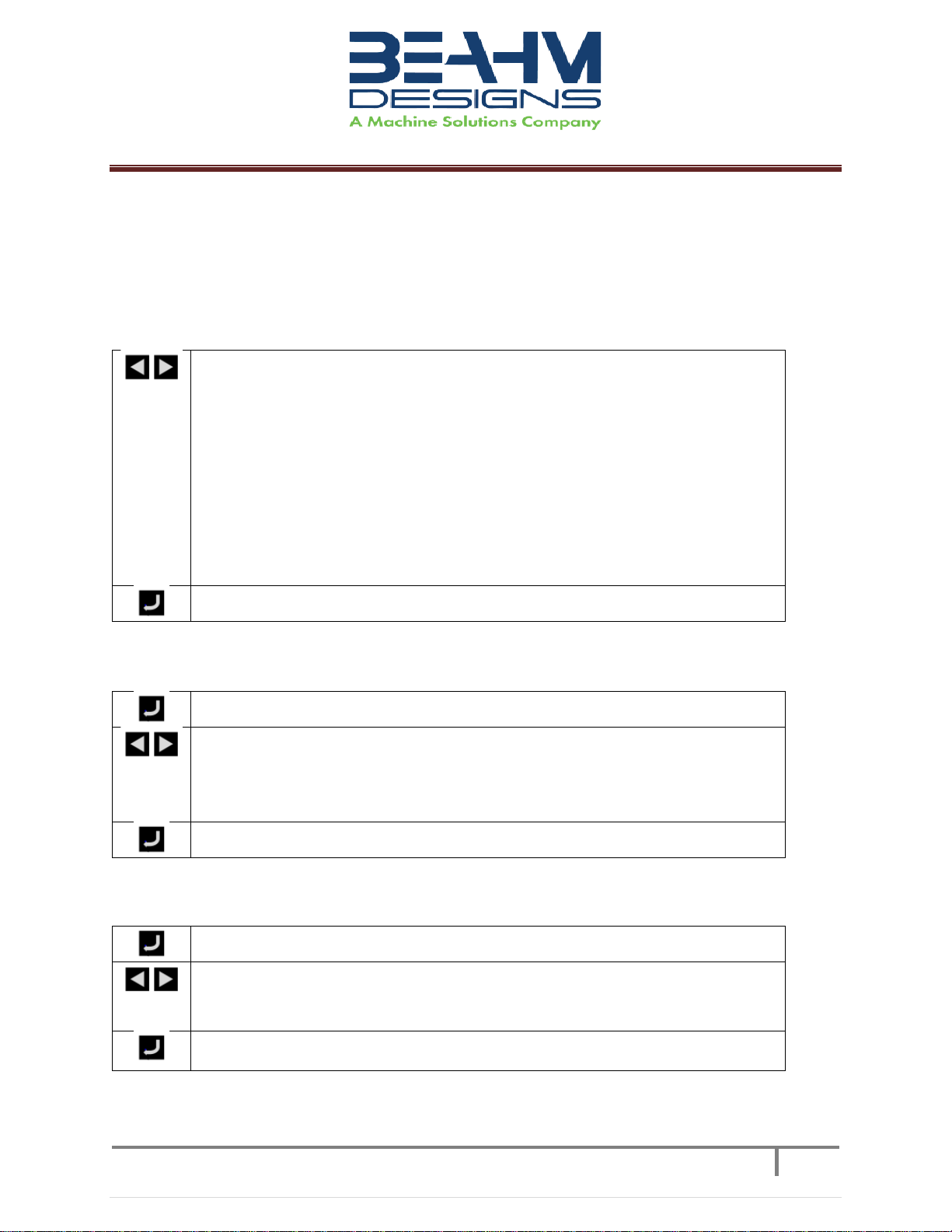
Adjusting Temperature on Controllers (Omega Platinum Model).....................................................9
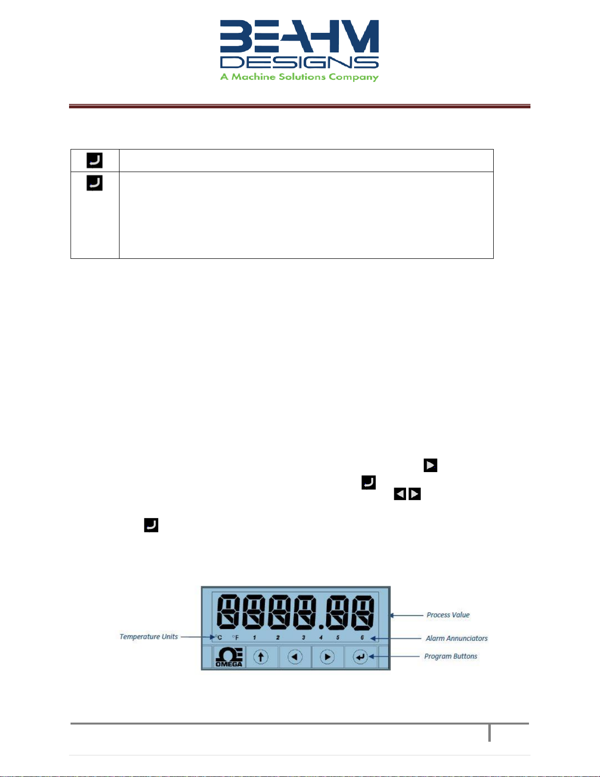
Temperature Controller Layout and Description of Button Actions..................................................9
Resetting the temperature controller .............................................................................................10
Changing Temperature Units on the Omega Temperature Controller............................................19
Maintenance...............................................................................................................................................19
Exchanging Die Heads.............................................................................................................................20
System Specifications.................................................................................................................................20
Calibration ..................................................................................................................................................20
Critical Spare Parts .....................................................................................................................................21
Diagnostics (Troubleshooting)...................................................................................................................21
Facilities Requirements..............................................................................................................................22
Warranty.....................................................................................................................................................22

© Copyright. Machine Solutions Inc. All Rights Reserved
PM-62082 Rev. B
3
Equipment User Manual
List of Tables
Table 1. Control and Display Functions .......................................................................................................6
Table 5. System Specifications...................................................................................................................20
Table 6. Critical Spare Parts .......................................................................................................................21
Table 7. Diagnostics (Troubleshooting).....................................................................................................21
List of Figures
Figure 1. 420-B Front Panel..........................................................................................................................6
Figure 2. Controller Layout ..........................................................................................................................9
Figure 3. Description of Button Actions ....................................................................................................10

© Copyright. Machine Solutions Inc. All Rights Reserved
PM-62082 Rev. B
4
Equipment User Manual
Welcome
Machine Solutions, Inc. (MSI) would like to take this opportunity to thank you for purchasing
your new 420-B Balloon Bonder machine. At MSI, we are dedicated to bringing innovative process
development solutions to both medical device and nonmedical organizations. The MSI proprietary
segmental technology has been successfully implemented in manufacturing clean rooms on five
continents, and continues to expand –meeting, growing, and facilitating the abilities of device
companies around the globe. MSI looks forward to helping your organization provide life-improving
devices to your customers, today and tomorrow.
Overview
Thermal Die Bonder with Axial Compression. This system is equipped with dual Pneumatic tubing
grips, centerline adjustment, adjustable compression, and variable timed cooling. The 420B provides a
low-cost quick tool alternative to RF die bonding. The seven-parameter operation is easy to set-up and
use and simplifies system calibration and process validation. This system provides you with fast, highly
repeatable bonds. It also allows you to perform highly precise bonds for demanding applications such as
short balloon bonds and ultra smooth lap & butt welds. Adjustable clamp pressure varies compression
force on joint. Ultra compact design provides you with greater workspace.
Contents
Included with the system are the following contents:
•Axial Compression Thermal Die Bonder
•IEC Power Cord
Installation
Note: See Maintenance section for facilities requirements
1. Place the system on a level, sturdy surface at an ergonomically viable height for the user.
2. Connect the electrical umbilical to the die base unit.
3. Connect the power cord to the main control unit.
4. Connect the air supply to the system and then to a clean, dry, and filtered compressed air
source.

© Copyright. Machine Solutions Inc. All Rights Reserved
PM-62082 Rev. B
5
Equipment User Manual
Safety
•Use of eye protection when working with compressed gases and heated materials is advised.
•The maximum observed Sound Pressure Level is below 70 dB(A).
Caution: high voltage. Remove power and use safety precautions when servicing.
Caution: hot surface. Contact may cause burn. Allow to cool before servicing.
Caution: pinch point. Keep hands and body parts clear while in operation.
User Alerts
Do not use the equipment other than as prescribed. Examples: Do not attempt to sit on or climb
on the equipment, do not place heavy objects or containers of liquid on the machine, do not to insert
any foreign objects into the machine and do not attempt to bypass any guards or otherwise operate the
machine in any manner other than that in which it is explicitly intended.
Installation
Note: The equipment is not for use with materials that can decompose or ignite below the
maximum operating temperature of the machine. Hazards are materials that outgas
hazardous substances and or ignite. (260°C/500°F)
Note: This equipment is not for use in an ATEX environment.

© Copyright. Machine Solutions Inc. All Rights Reserved
PM-62082 Rev. B
6
Equipment User Manual
Controls and Features
Located on the front panel are the following controls and/or displays and their function.
Description
Function
Main power switch
Toggles system power and air on and off.
Start switch
Initiates process sequence.
Stop/Abort/Reset
Interrupts the process sequence and resets the system timer.
Resets the system after power up and if E Stop is depressed
Front Die temperature
controller
Controls the temperature of the front die head.
Rear Die temperature
controller
Controls the temperature of the rear die head.
Axial Compression Delay
Timer
Controls compression delay time.
Weld Duration Timer
Controls the duration that the die heads are closed and/or in
contact with the product.
Cool Duration Timer
Controls the duration the cooling air flows.
E Stop
Disrupts power to heaters and internal components.
Table 1. Control and Display Functions
Figure 1. 420-B Front Panel
E-Stop
Die Head Pressure
Gauge
Grip Pressure
Gauge
Start Switch
Grip Pressure
Regulator Knob
Front Die Temperature
Controller
Rear Die Temperature
Controller
Axial Compression
Delay Timer
Weld Duration
Timer
Cool
Duration
Timer
Main Power Switch
Stop/Abort/
Reset Switch
Die Head Pressure
Regulator Knob

© Copyright. Machine Solutions Inc. All Rights Reserved
PM-62082 Rev. B
7
Equipment User Manual
Parameter Settings
Pressure Regulator Setting
•Rotate the regulator knob clockwise to increase air pressure, counterclockwise to decrease
air pressure output to the die head actuation cylinder.
Process Timer Setting
•Depress the upper half of the blue rocker buttons to increase time duration, depress the
lower half of the blue rocker button to decrease the time duration. Depress the timer reset
button to accept the new value.
System Operation
Hot die jaws will become hot during operation and depending on temperature set-point, can cause
severe skin burns if contact occurs.
1. Switch main power on.
2. Set the die temperature on EACH temperature controller.
3. Set heat timer to desired duration in seconds.
4. Set Axial Compression Delay Timer to desired duration in seconds.
5. Set Cool Timer to desired duration in seconds.
6. Adjust Die Head pressure.
7. Adjust Tubing Grip Pressure.
8. Position components to be bonded within thermal jaws.
9. Depress footswitch/push start button.
10. Remove components upon completion of cool duration.

© Copyright. Machine Solutions Inc. All Rights Reserved
PM-62082 Rev. B
8
Equipment User Manual
Temperature Controllers (Omega Platinum Model)
Please note, the Omega temperature controllers have been auto tuned and are set for optimal
performance. Contact Beahm Designs for further diagnostics and instructions.
PID Configuration (PRoG > PId.S)
Navigate to the desired setting. Settings include the following:
•ACtN –Action direction moves up or down to SP1.
•A.to –Autotuning Timeout sets a maximum amount of time for
Autotuning.
•AUto –Initiates Autotuning
•GAIN –Select the proportional, integral, and derivative factors for manual
tuning.
•%Lo –Low clamping limit for Pulse and Analog outputs
•%HI –High clamping limit for Pulse and Analog outputs
•AdPt –Fuzzy logic adaptive tuning
Select the desired parameter.
Action Response (PRoG > PId > ACtN)
Select the Direction (ACtN) parameter.
Navigate to the desired setting. Settings include the following:
•RVRS –“Reverse Action”: Increase to SP1, such as heating (factory default)
•dRCt –“Direct Action”: Decrease to SP1, such as cooling
•RVRS/dRCt –Increase or Decrease to SP1, such as heating/cooling
Select the indicated setting.
Autotune Timeout (PRoG > PId > A.to)
Select the Autotune Timeout (A.to) parameter.
Set the amount of time before the Autotune process gives up and times out
in Minutes and Seconds (MM.SS). Slowly responding systems should have a
longer time-out setting.
Select the indicated setting.

© Copyright. Machine Solutions Inc. All Rights Reserved
PM-62082 Rev. B
9
Equipment User Manual
Autotune (PRoG > PId > TUNE)
Select the Autotune (AUto) command. The unit displays StRt.
Confirm Autotune activation. The unit attempts to optimize the P, I, and d
settings by stimulating the system and measuring the response. If the A.to
time out period expires before the Autotune operation can complete, the
unit displays a failure message E007. If the Autotune operation completes
successfully, the unit displays the message “doNE” and the Run mode is
switched to IDLE.
The Autotune function will select the tuning algorithm depending on the stability of current
process and the error difference between current process and the Control Setpoint (SP1). If the
process is relatively stable (i.e: at room temperature), a bump test will be performed to
determine the plant characteristics.
If the process is hot, or if the process is within 10% of Control Setpoint, limit cycle oscillation
will be performed with the tuning setpoint taken at the process value when the Autotune
function is triggered. Autotuning may be performed as many times as needed or when the
operating conditions (i.e: process load, or setpoint) have changed significantly. To obtain good
tuning results, ensure the process is stable prior to triggering autotune function. The process is
stable when it is at ambient temperature, or it is tracking Control Setpoint (SP1) in auto mode.
Adjusting Temperature on Controllers (Omega Platinum Model)
1. Press the right arrow button one time until “SP-1” is displayed.
2. Press the enter button to access the temperature screen.
3. Use the left and right arrow buttons to set desired temperature.
4. Once the desired temperature is set, press the enter button to return to the main screen.
Heaters will ramp to correct temperature.
Temperature Controller Layout and Description of Button Actions
Figure 2. Controller Layout

© Copyright. Machine Solutions Inc. All Rights Reserved
PM-62082 Rev. B
10
Equipment User Manual
Figure 3. Description of Button Actions
NOTE: For a more detailed look at the complete menu structure, please refer to the following
pages. A full description of features can be found here:
https://assets.omega.com/manuals/M5451.pdf.
Resetting the temperature controller
NOTE: Press ‘↑’ to select the operator menu (Oper)
NOTE: See the following chart for the correct settings for the Beahm 420B. Settings to change
in RED.

© Copyright. Machine Solutions Inc. All Rights Reserved
PM-62082 Rev. B
11
Equipment User Manual
1. Initialization Mode Menu (INIt)
a. The following table maps the Initialization Mode (INIt) navigation:

© Copyright. Machine Solutions Inc. All Rights Reserved
PM-62082 Rev. B
12
Equipment User Manual

© Copyright. Machine Solutions Inc. All Rights Reserved
PM-62082 Rev. B
13
Equipment User Manual

© Copyright. Machine Solutions Inc. All Rights Reserved
PM-62082 Rev. B
14
Equipment User Manual

© Copyright. Machine Solutions Inc. All Rights Reserved
PM-62082 Rev. B
15
Equipment User Manual
2. Programming Mode Menu (PRoG)
a. The following table maps the Programming Mode (PRoG) navigation:

© Copyright. Machine Solutions Inc. All Rights Reserved
PM-62082 Rev. B
16
Equipment User Manual

© Copyright. Machine Solutions Inc. All Rights Reserved
PM-62082 Rev. B
17
Equipment User Manual

© Copyright. Machine Solutions Inc. All Rights Reserved
PM-62082 Rev. B
18
Equipment User Manual
3. Operating Mode Menu (oPER)
a. The following table maps the Operating Mode (oPER) navigation:

© Copyright. Machine Solutions Inc. All Rights Reserved
PM-62082 Rev. B
19
Equipment User Manual
Changing Temperature Units on the Omega Temperature Controller
1. Press the up button until “oPER” appears on the screen.
2. Press the right arrow until “1 NI t” appears on the screen. Press enter.
3. Press the right arrow until “RdG” appears on the screen. Press enter.
4. “dEC.P” should be on screen. Press right arrow to show “°F °C” on the screen. Press
enter.
5. Use arrows to switch from °C to °F. Press enter.
6. Press the up arrow to go back to the “1 NI t” screen. Press the left arrow to go
back to “oPER”. Press enter to see “RUN” and press enter again to return to
normal operating status.
Maintenance
Caution: pinch point/crush hazard. Keep fingers, hands, and clothing clear of moving parts.
1. Use 99% isopropyl alcohol to wipe down the outside of the machine. Do not attempt to clean
the inside of the machine. Machine should not be washed down.
2. Cleaning should be with a soft dry cloth only.
Warning
Note: Ensure the machine is unplugged for any servicing or maintenance work.
Note: Perform these steps ONLY when the machine is at room temperature.

© Copyright. Machine Solutions Inc. All Rights Reserved
PM-62082 Rev. B
20
Equipment User Manual
Exchanging Die Heads
Caution: ensure that the die heads are cooled to within 15 degrees of ambient temperature before
proceeding with replacement.
•Loosen the set screw located on the top of each die head and withdraw the thermocouple.
•Remove the four screws at the base of each die head.
•Position new die heads in place of removed die heads, install four screws at the base of each die
head. Do not overtighten the screws.
•Install the thermocouple in the rear of each die head and gently tighten the set screw to hold
them in place.
System Specifications
Description
Range
Resolution
Accuracy
Temperature
Controller
Ambient-500°F
1.0 deg.
±.25% F.S.
Die Temperature
Ambient-500°F
N/A
±10°F
Heat Duration
1-9999 seconds
1.0 sec
± .1 sec
Cool Duration
1-9999 seconds
1.0 sec
± .1 sec
Die Pressure
0-60 psi
2.0 psi
± 1.5% F.S.
Table 2. System Specifications
Calibration
IMPORTANT NOTES:
A) It is recommended that calibration be performed by a certified service, preferably with
the system in the location of use. Calibration procedures are the domain of these service
providers.
B) Calibration refers to the process of verifying that each of the systems’ instruments that
control a process parameter is within manufacturers’ specification.
C) Calibration DOES NOT refer to the process of measuring the temperature at the center of
the tooling and “matching” the value to the temperature controller set point.
D) The measured value at the tooling may not match the temperature controller set point
and the.
1. Calibrate the temperature controller annually.
2. Calibrate the timers annually.
3. Calibrate the pressure gauge annually.
Table of contents
Other MACHINE SOLUTIONS Industrial Equipment manuals
Popular Industrial Equipment manuals by other brands

NZXT
NZXT Sentry LX user manual

Titgemeyer
Titgemeyer SAN2URCap Implemenation Guide

HYDAC FILTER SYSTEMS
HYDAC FILTER SYSTEMS FluidAqua Mobil FAM 5 Operating and maintenance instructions

Dynalabs
Dynalabs DYN-PM-440 product manual

Adey
Adey MagnaClean CP1-03-01123 Installation and servicing

Axminster
Axminster PROfessional AP330ST Original instructions