MACHINE SOLUTIONS BEAHM DESIGNS 43-B User manual

BEAHM DESIGNS BENCH TOP DIE NECKER
MODEL 43-B

© Copyright. Machine Solutions Inc. All Rights Reserved
PM-62319 REV B
2
Equipment User Manual
Table Of Contents
Welcome ......................................................................................................................................... 3
Purpose ........................................................................................................................................... 3
Overview......................................................................................................................................... 3
Contents.......................................................................................................................................... 3
Installation ...................................................................................................................................... 3
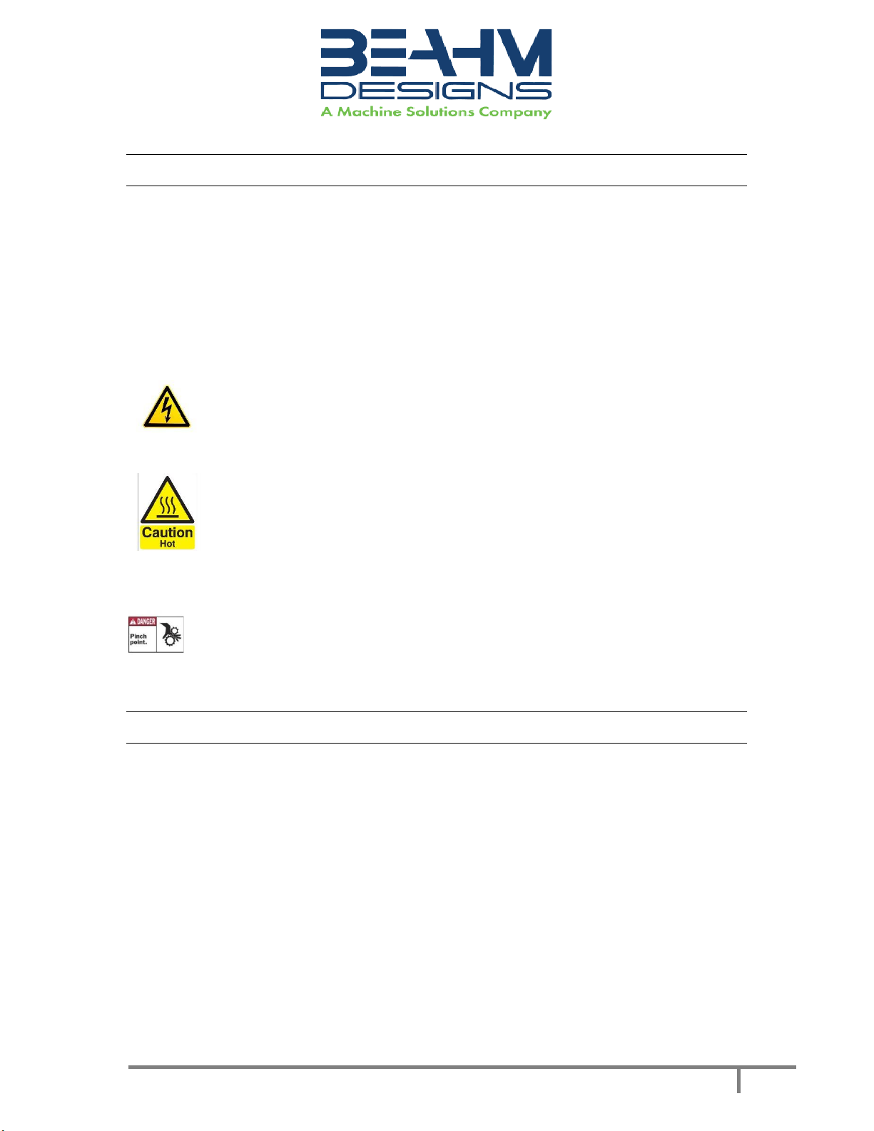
Safety............................................................................................................................................... 4
User Alerts....................................................................................................................................... 4
Die Head Replacement ................................................................................................................... 5
Parameter Settings ......................................................................................................................... 5
Cooling Air ON Toggle.................................................................................................................. 5
Cooling Air Flow Adjust................................................................................................................ 5
System Operations.......................................................................................................................... 5
Temperature Controllers (Omega Platinum Model) .................................................................... 6
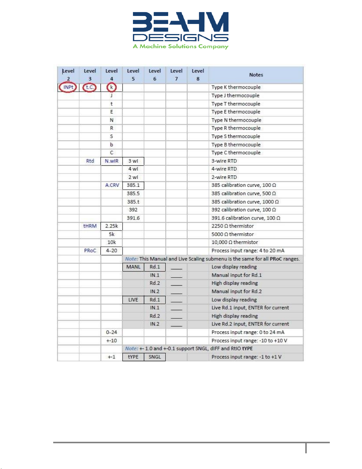
PID Configuration (PRoG > PId.S)................................................................................................. 6
Action Response (PRoG > PId > ACtN).......................................................................................... 6
Autotune Timeout (PRoG > PId > A.to) ........................................................................................ 6
Autotune (PRoG > PId > TUNE) .................................................................................................... 7
Adjusting Temperature on Controllers (Omega Platinum Model) ............................................... 7
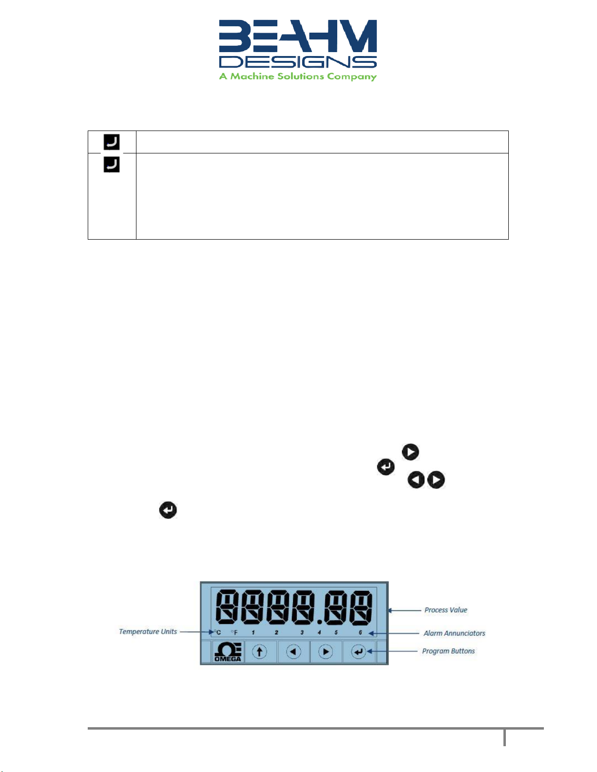
Temperature Controller Layout and Description of Button Actions ............................................ 7
Resetting the temperature controller.......................................................................................... 8
Changing Temperature Units on the Omega Temperature Controller ...................................... 17
Maintenance................................................................................................................................. 17
Facility Requirements ................................................................................................................ 18
Warranty....................................................................................................................................... 18
Return Material Authorization.................................................................................................. 18

© Copyright. Machine Solutions Inc. All Rights Reserved
PM-62319 REV B
3
Equipment User Manual
Welcome
Machine Solutions, Inc. (MSI) would like to take this opportunity to thank you for
purchasing your new 43-B Bench Top Die Necker. At MSI, we are dedicated to bringing
innovative process development solutions to both medical device and nonmedical
organizations. MSI looks forward to helping your organization provide life-improving
devices to your customers, today and tomorrow.
Purpose
The purpose of this document is to describe the electrical and software design of
the control system for the Split Die Thermal Bonder, 43-B. This document also includes
operator instructions.
Overview
The Beahm Designs Die Necker progressively reduces tubing diameter by means of a
heated die. Tubing is manually drawn through the die to the desired length. The I.D. of the
interchangeable dies controls the diameter of the neck tubing.
Contents
1. Benchtop Die Necker
2. Power cord
Installation
1. Place the system on a level, sturdy surface at an ergonomically viable height for
the user.
2. System power is in the OFF position.
3. Connect the power cord to the main control unit.
4. Connect the air supply to the system and then to a clean, dry, and filtered
compressed air source.
5. Connect the electrical umbilical to the die base unit.

© Copyright. Machine Solutions Inc. All Rights Reserved
PM-62319 REV B
4
Equipment User Manual
Safety
Note: See Maintenance section for facilities requirements
•Place the system on a level, sturdy surface at an ergonomically viable height for
the user.
•Use of eye protection when working with compressed gases and heated
materials is advised.
•The maximum observed Sound Pressure Level is below 70 dB(A).
•Hot dies will become hot during operation and, depending on temperature set-
point, can cause severe skin burns if contact occurs.
Caution: high voltage. Remove power and use safety precautions when
servicing. Power down machine before disconnecting umbilical.
Caution: hot surface. Contact may cause burn. Allow to cool before
servicing.
Caution: pinch point. Keep hands and body parts clear while in
operation.
User Alerts
Do not use the equipment other than as prescribed. Examples: Do not attempt
to sit on or climb on the equipment, do not place heavy objects or containers of liquid
on the machine, do not to insert any foreign objects into the machine and do not
attempt to bypass any guards or otherwise operate the machine in any manner other
than that in which it is explicitly intended.
Note: The equipment is not for use with materials that can decompose or ignite below
the maximum operating temperature of the machine. Hazards are materials that
outgas hazardous substances and or ignite. (260°C/500°F).
Note: This equipment is not for use in an ATEX environment.
Note: Power down machine before disconnecting umbilical.

© Copyright. Machine Solutions Inc. All Rights Reserved
PM-62319 REV B
5
Equipment User Manual
Die Head Replacement
Caution: ensure the die heads are cooled to within 15 degrees °F of ambient
temperature before proceeding with replacement.
Required Tools and Equipment
2 open end or similar wrenches
1. Remove the 4 screws holding the heat shield.
2. Remove the heat shield.
3. Loosen the clamping nut and bolt located at the top and bottom of the heater housing.
4. Remove the existing die from the housing and replace it with alternate size die.
5. Tighten the clamping nut and bolt until the die is secure in the housing.
6. Reinstall the heat shield.
Parameter Settings
Cooling Air ON Toggle
•Place toggle in the up position for cooling air On, and toggle down for
cooling air Off.
Cooling Air Flow Adjust
•Rotate the Cooling Flow valve counterclockwise to increase the cooling
air flow, and clockwise to decrease the cooling air flow.
System Operations
CAUTION: Die housing and drawing dies will become hot during operation and,
depending on temperature set-point, can cause severe skin burns if contact occurs.
1. Switch main power on.
2. Set die temperature on temperature controller by pressing the UP button once to see
“SP1” displayed. Press the Enter button to display temperature. Use Left/Right arrows to
set desired temperature. Once the desired temperature is set, press the Enter button to
return to home.
3. Pass end of tubing through the necking die and grasp at opposite side.
4. Draw tubing through die at a speed that produces the desired tubing o.d.
5. To aid in obtaining tubing diameter, position the cooling air nozzle near the exit of the
drawing die and switch cooling air “on” as tubing is drawn through the die.

© Copyright. Machine Solutions Inc. All Rights Reserved
PM-62319 REV B
6
Equipment User Manual
Temperature Controllers (Omega Platinum Model)
Please note, the Omega temperature controllers have been auto tuned and are set for
optimal performance. Contact Beahm Designs for further diagnostics and instructions.
PID Configuration (PRoG > PId.S)
Navigate to the desired setting. Settings include the following:
•ACtN –Action direction moves up or down to SP1.
•A.to –Autotuning Timeout sets a maximum amount of time for
Autotuning.
•AUto –Initiates Autotuning
•GAIN –Select the proportional, integral, and derivative factors for manual
tuning.
•%Lo –Low clamping limit for Pulse and Analog outputs
•%HI –High clamping limit for Pulse and Analog outputs
•AdPt –Fuzzy logic adaptive tuning
Select the desired parameter.
Action Response (PRoG > PId > ACtN)
Select the Direction (ACtN) parameter.
Navigate to the desired setting. Settings include the following:
•RVRS –“Reverse Action”: Increase to SP1, such as heating (factory
default)
•dRCt –“Direct Action”: Decrease to SP1, such as cooling
•RVRS/dRCt –Increase or Decrease to SP1, such as heating/cooling
Select the indicated setting.
Autotune Timeout (PRoG > PId > A.to)
Select the Autotune Timeout (A.to) parameter.
Set the amount of time before the Autotune process gives up and times out
in Minutes and Seconds (MM.SS). Slowly responding systems should have a
longer time-out setting.
Select the indicated setting.

© Copyright. Machine Solutions Inc. All Rights Reserved
PM-62319 REV B
7
Equipment User Manual
Autotune (PRoG > PId > TUNE)
Select the Autotune (AUto) command. The unit displays StRt.
Confirm Autotune activation. The unit attempts to optimize the P, I, and d
settings by stimulating the system and measuring the response. If the A.to
time out period expires before the Autotune operation can complete, the
unit displays a failure message E007. If the Autotune operation completes
successfully, the unit displays the message “doNE” and the Run mode is
switched to IDLE.
The Autotune function will select the tuning algorithm depending on the stability of
current process and the error difference between current process and the Control
Setpoint (SP1). If the process is relatively stable (i.e: at room temperature), a bump test
will be performed to determine the plant characteristics.
If the process is hot, or if the process is within 10% of Control Setpoint, limit cycle
oscillation will be performed with the tuning setpoint taken at the process value when
the Autotune function is triggered. Autotuning may be performed as many times as
needed or when the operating conditions (i.e: process load, or setpoint) have changed
significantly. To obtain good tuning results, ensure the process is stable prior to
triggering autotune function. The process is stable when it is at ambient temperature, or
it is tracking Control Setpoint (SP1) in auto mode.
Adjusting Temperature on Controllers (Omega Platinum Model)
1. Press the right arrow button one time until “SP-1” is displayed.
2. Press the enter button to access the temperature screen.
3. Use the left and right arrow buttons to set desired temperature.
4. Once the desired temperature is set, press the enter button to return to the main
screen. Heaters will ramp to correct temperature.
Temperature Controller Layout and Description of Button Actions
Figure 1. Controller Layout

© Copyright. Machine Solutions Inc. All Rights Reserved
PM-62319 REV B
8
Equipment User Manual
Figure 2. Description of Button Actions
NOTE: For a more detailed look at the complete menu structure, please refer to the
following pages. A full description of features can be found here:
https://assets.omega.com/manuals/M5451.pdf.
Resetting the temperature controller
NOTE: Press ‘↑’ to select the operator menu (Oper)
NOTE: See the following chart for the correct settings for the Beahm 43-B. Settings to
change in RED.
1. Initialization Mode Menu (INIt)
a. The following table maps the Initialization Mode (INIt) navigation:

© Copyright. Machine Solutions Inc. All Rights Reserved
PM-62319 REV B
9
Equipment User Manual

© Copyright. Machine Solutions Inc. All Rights Reserved
PM-62319 REV B
10
Equipment User Manual

© Copyright. Machine Solutions Inc. All Rights Reserved
PM-62319 REV B
11
Equipment User Manual

© Copyright. Machine Solutions Inc. All Rights Reserved
PM-62319 REV B
12
Equipment User Manual

© Copyright. Machine Solutions Inc. All Rights Reserved
PM-62319 REV B
13
Equipment User Manual
2. Programming Mode Menu (PRoG)
a. The following table maps the Programming Mode (PRoG) navigation:

© Copyright. Machine Solutions Inc. All Rights Reserved
PM-62319 REV B
14
Equipment User Manual

© Copyright. Machine Solutions Inc. All Rights Reserved
PM-62319 REV B
15
Equipment User Manual

© Copyright. Machine Solutions Inc. All Rights Reserved
PM-62319 REV B
16
Equipment User Manual
3. Operating Mode Menu (oPER)
a. The following table maps the Operating Mode (oPER) navigation:

© Copyright. Machine Solutions Inc. All Rights Reserved
PM-62319 REV B
17
Equipment User Manual
Changing Temperature Units on the Omega Temperature Controller
1. Press the up button until “oPER” appears on the screen.
2. Press the right arrow until “1 NI t” appears on the screen. Press enter.
3. Press the right arrow until “RdG” appears on the screen. Press enter.
4. “dEC.P” should be on screen. Press right arrow to show “°F °C” on the screen.
Press enter.
5. Use arrows to switch from °C to °F. Press enter.
6. Press the up arrow to go back to the “1 NI t” screen. Press the left arrow
to go back to “oPER”. Press enter to see “RUN” and press enter again
to return to normal operating status.
Maintenance
Caution: pinch point/crush hazard. Keep fingers, hands, and clothing
clear of moving parts.
1. Use 99% isopropyl alcohol to wipe down the outside of the machine. Do not
attempt to clean the inside of the machine. The machine should not be washed
down.
2. Cleaning should be with a soft dry cloth only.
Warning
Note: Ensure the machine is unplugged for any servicing or maintenance work.
Note: Perform these steps ONLY when the machine is at room temperature.

© Copyright. Machine Solutions Inc. All Rights Reserved
PM-62319 REV B
18
Equipment User Manual
Critical Spare Parts (Contact Beahm Designs for pricing)
P/N
Description
120V –1153590-001
220V –1157788-001
HEATRER CARTRIDGE
1143133-001
THERMOCOUPLE, K TYPE, 0.125 OD.SLDPRT
1161899-001
TEMPERATURE CONTROLLER
1155195-001
SOLID STATE RELAY
1114668-005
24VDC POWER SUPPLY
Table 1. Critical Spare Parts
Facility Requirements
1. Voltage: 120-240 VAC, 50/60 hz
2. Wattage: 10 amps (500 watts)
3. Compressed Air: 100-125 psi, clean dry compressed air
Warranty
Beahm Designs Inc. (BDI) products are backed by a 1-year warranty on parts and labor.
Warranty is void for any product returned if BDI determines that:
a. The asserted defect is not present,
b. The asserted defect is attributed to misuse, improper installation,
alteration (label removal and/or destruction, opening or removing
external covers without authorization by Beahm Designs Inc.),
mishandling and/or mishaps.
c. The product was not sold to customer as new.
Return Material Authorization
Product may not be returned to Beahm Designs Inc. without first contacting BDI
Aftermarket for a Return Material Authorization (RMA) number. If it is determined that
the Product may be defective, you will be given an RMA number and instructions for
Product return. End Users are required to include a copy of the RMA receipt inside the
return box, in order to receive replacement product under the warranty. All
unauthorized returns i.e., one for which an RMA number has not been issued, will be
returned at the customers expense. To request an RMA, please contact us at 928-556-
3109 or email [email protected]
For additional information on Beahm Designs, Split Die Thermal Bonder, please visit
http://machinesolutions.com/our-products/
Table of contents
Other MACHINE SOLUTIONS Industrial Equipment manuals
Popular Industrial Equipment manuals by other brands

BANDELIN
BANDELIN BactoSonic User instructions

Schulte
Schulte FX-742 Operator's manual

Festo
Festo MS6-SV Series operating instructions

Kilews
Kilews KFA-0850H instruction manual

KSB
KSB AmaDrainer Box Box Z2 B Installation & operating manual

Outdoor Water Solutions
Outdoor Water Solutions Large Wood Windmill Assembly instructions