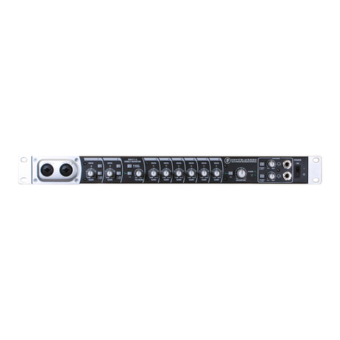
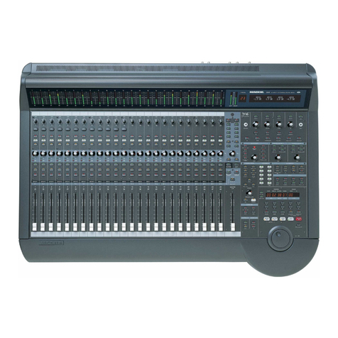
Mackie Onyx 1200F User manual

OWNER’S MANUAL
STUDIO RECORDING PREAMP
with 192kHz FIREWIRE INTERFACE

2
ONYX 1200F
ONYX 1200F
1. Read these instructions.
2. Keep these instructions.
3. Heed all warnings.
4. Follow all instructions.
5. Do not use this apparatus near water.
6. Clean only with dry cloth.
7. Do not block any ventilation openings. Install in accordance with the
manufacturer’s instructions.
8. Do not install near any heat sources such as radiators, heat registers,
stoves, or other apparatus (including amplifiers) that produce heat.
9. Do not defeat the safety purpose of the polarized or grounding-type
plug. A polarized plug has two blades with one wider than the other.
A grounding-type plug has two blades and a third grounding prong.
The wide blade or the third prong are provided for your safety. If the
provided plug does not fit into your outlet, consult an electrician for
replacement of the obsolete outlet.
10.
Protect the power cord from being walked on or pinched particularly at
plugs, convenience receptacles, and the point where they exit from the
apparatus.
11.
Only use attachments/accessories specified by the manufacturer.
12.
Use only with a cart, stand, tripod, bracket, or
table specified by the manufacturer, or sold with
the apparatus. When a cart is used, use caution
when moving the cart/apparatus combination to
avoid injury from tip-over.
13.
Unplug this apparatus during lightning storms or
when unused for long periods of time.
14.
Refer all servicing to qualified service personnel. Servicing is required
when the apparatus has been damaged in any way, such as power-
supply cord or plug is damaged, liquid has been spilled or objects have
fallen into the apparatus, the apparatus has been exposed to rain or
moisture, does not operate normally, or has been dropped.
15.
This apparatus shall not be exposed to dripping or splashing, and no
object filled with liquids, such as vases, shall be placed on the apparatus.
16.
This apparatus has been designed with Class-I construction and must
be connected to a mains socket outlet with a protective earthing con-
nection (the third grounding prong).
17.
This apparatus has been equipped with a single-pole, rocker-style AC
mains power switch. This switch is located on the front panel and
should remain readily accessible to the user.
18.NOTE: This equipment has been tested and found to comply with
the limits for a Class B digital device, pursuant to part 15 of the FCC
Rules. These limits are designed to provide reasonable protection
against harmful interference in a residential installation. This
equipment generates, uses, and can radiate radio frequency energy
and, if not installed and used in accordance with the instructions,
may cause harmful interference to radio communications. However,
there is no guarantee that interference will not occur in a particular
installation.
If this equipment does cause harmful interference to radio or
television reception, which can be determined by turning the
equipment off and on, the user is encouraged to try to correct the
interference by one or more of the following measures:
• Reorientorrelocatethereceivingantenna.
• Increasetheseparationbetweentheequipmentandthereceiver.
• Connecttheequipmentintoanoutletonacircuitdifferentfrom
that to which the receiver is connected.
• Consultthedealeroranexperiencedradio/TVtechnicianforhelp.
CAUTION: Changes or modifications to this device not expressly
approved by LOUD Technologies Inc. could void the user’s authority to
operate the equipment under FCC rules.
19.
This apparatus does not exceed the Class A/Class B (whichever is
applicable)
limits for radio noise emissions from digital apparatus as
set out in the radio interference regulations of the Canadian Department
of Communications.
ATTENTION — Le présent appareil numérique n’émet pas de bruits
radioélectriques dépassant las limites applicables aux appareils numériques de
class A/de class B (selon le cas) prescrites dans le réglement sur le brouillage
radioélectrique édicté par les ministere des communications du Canada.
20.
Exposure to extremely high noise levels may cause permanent hearing
loss. Individuals vary considerably in susceptibility to noise-induced
hearing loss, but nearly everyone will lose some hearing if exposed to
sufficiently intense noise for a period of time. The U.S. Government’s
Occupational Safety and Health Administration (OSHA) has specified
the permissible noise level exposures shown in the following chart.
According to OSHA, any exposure in excess of these permissible limits
could result in some hearing loss. To ensure against potentially danger-
ous exposure to high sound pressure levels, it is recommended that all
persons exposed to equipment capable of producing high sound pres-
sure levels use hearing protectors while the equipment is in operation.
Ear plugs or protectors in the ear canals or over the ears must be worn
when operating the equipment in order to prevent permanent hearing
loss if exposure is in excess of the limits set forth here.
Important Safety Instructions
Correct Disposal of this product: This symbol indicates that this product should not be disposed of with your household waste, according to the WEEE Directive
(2002/96/EC) and your national law. This product should be handed over to an authorized collection site for recycling waste electrical and electronic equipment (EEE). Improper handling
of this type of waste could have a possible negative impact on the environment and human health due to potentially hazardous substances that are generally associated with EEE. At the
same time, your cooperation in the correct disposal of this product will contribute to the effective usage of natural resources. For more information about where you can drop off your waste
equipment for recycling, please contact your local city office, waste authority, or your household waste disposal service.
PORTABLE CART
WARNING
CAUTION
RISK OF ELECTRIC SHOCK. DO NOT OPEN
CAUTION: TO REDUCE THE RISK OF ELECTRIC SHOCK DO NOT REMOVE COVER (OR BACK)
NO USER-SERVICEABLE PARTS INSIDE. REFER SERVICING TO QUALIFIED PERSONNEL
The lightning flash with arrowhead symbol within an equilateral triangle is
intended to alert the user to the presence of uninsulated "dangerous
voltage" within the product's enclosure, that may be of sufficient magnitude
to constitute a risk of electric shock to persons.
The exclamation point within an equilateral triangle is intended to alert the
user of the presence of important operating and maintenance (servicing)
instructions in the literature accompanying the appliance.
WARNING — To reduce the risk of fire or electric shock, do not
expose this apparatus to rain or moisture.
Duration, per
day in hours Sound Level dBA,
Slow Response Typical Example
8 90 Duo in small club
6 92
4 95 Subway Train
3 97
2 100 Veryloudclassicalmusic
1.5 102
1 105 Fooyoung screaming at desTROYer about deadlines
0.5 110
0.25 or less 115 Loudest parts at a rock concert

Part No. SW0597 Rev. B 03/12
©2007-2012 LOUD Technologies Inc. All Rights Reserved.
3
Owner’s Manual
Owner’s Manual
Don’t forget to visit our website at www.mackie.com for more
information about this and other Mackie products.
R
Table of Contents
Introduction ................................................................................................................................. 5
Getting Started ...........................................................................................................................7
Zero the Controls ....................................................................................................................................................................7
Connections ..............................................................................................................................................................................7
Set the Levels ...........................................................................................................................................................................7
Record to CD Using the DAW Mixer ..................................................................................................................................7
Record to CD Using the DSP Mixer ................................................................................................................................... 8
Standalone Mode .................................................................................................................................................................. 8
Hookup Diagrams ..................................................................................................................... 10
Onyx 1200F Features................................................................................................................. 14
Front Panel ..............................................................................................................................................................................14
1. Signal Level Indicators ..................................................................................................................................................14
2. 48V Phantom Power Switch ......................................................................................................................................14
3. LINE Switch......................................................................................................................................................................14
4. Channel GAIN ................................................................................................................................................................14
5. Instrument Input ...........................................................................................................................................................14
6. Instrument Switch ........................................................................................................................................................15
7. PHONES 1-4 Level ...........................................................................................................................................................15
8. PHONES 1-4 Outputs ....................................................................................................................................................15
9. CLOCK SOURCE Select and Indicators ....................................................................................................................15
10. METERING Select and Indicators ............................................................................................................................16
11. SAMPLE RATE Select and Indicators .......................................................................................................................16
12. FireWire Indicator .......................................................................................................................................................16
13. MIDI Indicators .............................................................................................................................................................16
14. TALK TO PHONES Level Control ..............................................................................................................................16
15. TALK TO PHONES On/Off Switch ..........................................................................................................................16
16. OUTPUTS 1-8 Level Control ......................................................................................................................................16
17. Output Level BYPASS ..................................................................................................................................................17
18. MONITOR Level Control ...........................................................................................................................................17
19. MONITOR A/B Select Switch ..................................................................................................................................17
20. Power Switch ...............................................................................................................................................................17
Rear Panel ...............................................................................................................................................................................17
21. MIC/Line Inputs ...........................................................................................................................................................17
22. INSERTS ..........................................................................................................................................................................17
23. TALKBACK MIC .............................................................................................................................................................18

4
ONYX 1200F
ONYX 1200F
Please write your serial number here for future
reference (i.e., insurance claims, tech support,
return authorization, etc.)
Purchased at:
Date of purchase:
24. CONTROL RM MONITORS A/B .............................................................................................................................18
25. MIDI IN/OUT (1 and 2) ...............................................................................................................................................18
26. FIREWIRE ......................................................................................................................................................................18
27. AES/EBU IN/OUT .......................................................................................................................................................19
28. S/PDIF IN/OUT ...........................................................................................................................................................19
29. ADAT IN/OUT (A/B) .................................................................................................................................................20
30. EXTERNAL WORD CLOCK IN/OUT.......................................................................................................................20
31. 8 CHANNEL BALANCED LINE LEVEL OUTPUT ......................................................................................................21
32. MON A/B FOOTSWITCH ..........................................................................................................................................21
33. TALKBACK FOOTSWITCH ..........................................................................................................................................21
34. AC Power Receptacle .................................................................................................................................................21
Onyx 1200F Console ..................................................................................................................21
Installing the Software ........................................................................................................................................................21
Computer Requirements .................................................................................................................................................21
A Note about Hard Drive Speed: ...................................................................................................................................21
Installing the Drivers and Onyx 1200F Console ....................................................................................................... 22
Macintosh OS X Audio MIDI Setup ..............................................................................................................................23
Installing Tracktion ..........................................................................................................................................................24
Using the Onyx 1200F Console .........................................................................................................................................24
Settings ................................................................................................................................................................................ 25
Outputs ...............................................................................................................................................................................28
Standalone Mode .............................................................................................................................................................29
Appendix A: Service Information .........................................................................................30
Troubleshooting ...................................................................................................................................................................30
Repair ....................................................................................................................................................................................... 31
Appendix B: Connections ....................................................................................................... 32
Appendix C: Technical Info ....................................................................................................34
Onyx 1200F Specifications .................................................................................................................................................. 34
Onyx 1200F Block Diagram ................................................................................................................................................. 36
Onyx 1200F Limited Warranty ..............................................................................................39

5
Owner’s Manual
Owner’s Manual
Introduction
Thank you for choosing a Mackie Onyx 1200F profes-
sional audio interface for live or studio analog or digital
audio recording. The 1200F is equipped with twelve
of our Onyx Series precision-engineered studio-grade
microphone preamps, designed for the digital era and
offering the newest features and latest technologies for
live sound reinforcement and analog or digital studio
recording in a durable, road-worthy package. Its selec-
tion of analog and digital output options provides the
flexibility to connect in almost any application (includ-
ing an HDR in standalone mode).
Mackie is renowned for the high-quality mic preamps
used in our mixers, and the Onyx mic pre’s are better
than ever, with specifications rivaling other stand-alone
boutique mic preamplifiers at twice the price.
Channels 1 and 2 have balanced send and return in-
sert jacks for connecting to an external signal processor.
Channels 11 and 12 feature an unbalanced instrument
input jack and select switch, which lets you connect an
acoustic, electric, or bass guitar pickup directly to the
preamp, eliminating the need for an external direct box.
Channels 1-12 have Neutrik™ Combo input connec-
tors, which allows you to use either a 1/4” TRS connec-
tor or an XLR connector. A 48V switch is provided for
each channel and applies phantom power to pins 2 and
3 of the channel’s XLR input connector.
Two pairs of balanced control room monitor outputs
are provided for connecting to powered monitors (or
power amplifier/monitor combination), and can be
sourced from the audio streams for any adjacent pair
of analog outputs, stereo headphone outputs, or the
S/PDIF or AES/EBU outputs.
Eight channels of analog balanced line outputs are
provided on a DB-25 connector. Two channels of digital
inputs and outputs are provided on two S/PDIF RCA-
type connectors and two AES/EBU XLR connectors. Up to
30 input channels and 34 output channels of digital I/O
(at 44.1/48 kHz) are provided on the FireWire connec-
tors (see chart below). There are two FireWire connec-
tors so the Onyx 1200F can be placed in a daisy-chain
FireWire connection. Two pairs of ADAT optical con-
nectors are included, which provide up to 16 channels
of ADAT formatted digital I/O (16 channels at 44.1/48
kHz and 8 channels at 88.2/96 kHz). Two sets of MIDI
IN/OUT connectors are provided for sending and receiv-
ing MIDI information.
The Onyx 1200F is designed to be a transparent audio
interface for direct tracking to a DAW recording applica-
tion on a PC or Mac. All 30 inputs are directly available
to the DAW application over the FireWire connection
(when operating at 44.1/48 kHz). The Console software
application allows you to route any input to any analog
or digital output on the 1200F, along with a pair of out-
puts from the DAW. This provides you with the choice of
direct monitoring, without going through the FireWire
connection and DAW software (zero latency), or moni-
toring through the DAW application.
You can provide a separate mix for each of the four
headphone outputs from any of the inputs and from two
of the outputs from the DAW. A talkback mic can be
routed to the four headphone outputs, operated from a
front panel button or a footswitch.
The Onyx 1200F Console Settings tab allows you to
choose the sample rate (44.1, 48, 88.2, 96, 176.4, or
192 kHz
) for the internal A/D and D/A converters. You
can select the clock source from an external clock con-
nected to the external word clock (WordClk) input con-
nector on the rear panel, from the S/PDIF or AES/EBU
input, from the ADAT 1 or ADAT 2 input, or from the
internal clock. You can turn the DSP Mixer on and off,
which allows you to operate the 1200F as a matrix mixer
with digital streams to a computer (DSP ON), or as a
standalone digital audio interface with digital streams
to and from a computer (DSP OFF). You can select
which inputs are routed to the Control Room outputs,
and whether the S/PDIF I/O is formatted for consumer
or professional status. You can adjust the buffer size
(latency), and select which I/O audio streams are active
on the FireWire connection.
Qty Inputs ASIO/Core Audio Stream
12 Mic/Line Inputs 1-12
8 Digital A Inputs 13-20
8 Digital B Inputs 21-28
2 S/PDIF/AES Inputs 29-30
30 Total Inputs
Onyx 1200F Input/Output Chart
Qty Outputs ASIO/Core Audio Stream
8 Analog Outputs 1-8
8 Digital A Outputs 9-16
8 Digital B Outputs 17-24
8 Headphone Outputs (4x2) 25-32
2 S/PDIF/AES Outputs 33-34
34 Total Outputs
Note: The ASIO/Core Audio Stream assignments shown here apply when 44.1/48 kHz sample rate is selected.
At higher sample rates, the digital outputs are multiplexed using the S/MUX format, which reduces the number of
ASIO/Core Audio channels available for streaming. You can choose the inputs and outputs that are streamed to the DAW
at the higher sample rates in the Console’s Settings window.

6
ONYX 1200F
ONYX 1200F
Onyx 1200F Features
• Premium30-inputx34-outputRecordingPreamp/
FireWire Audio Interface
• 12agshipOnyxmicpreampswithclass-leading
fidelity and dynamic range
• Mastering-gradeAKM®24-bit/192kHzA/DandD/A
converters
• DualFireWireportsfordaisychaininganddirect
connection to Mac or PC
• 8balancedlineoutputsvia25-pinD-Subconnector
• 16x16ADATI/O@44.1/48kHz
(8x8@88.2/96kHz;disabled@176.4/192kHz)
• 4headphoneoutputswithvolumecontrolanddis-
crete stereo feeds
• PowerfulonboardDSPMatrixMixer:connectany
input to any output at near-zero latency
• Built-incontrolroomfunctions:A/BMonitor
Switching, Talkback, plus stereo and up to 7.1 sur-
round output main volume control
• BalancedTRSsendandreturninsertjackson
Inputs 1 and 2
•
2x2 MIDI, plus Word Clock, AES/EBU and S/PDIF I/O
• Stand-alonemixerfunctionalityforeldandstudio
use without computer
•
Includes full version of Tracktion Music Production
Software for digital audio recording
HOW TO USE THIS MANUAL
We know that many of you can’t wait to get your
new preamp/FireWire interface hooked up, and you’re
probably not going to read the manual first (sigh!). So
the first section after this introduction is a Quick-Start
Guide called “Getting Started” to help you get the Onyx
1200F set up fast so you can start using it right away.
Right after that are the ever popular hook-up diagrams
that show typical setups for recording.
Then, when you have time, read the Features Descrip-
tion section. This describes every knob, button, and con-
nection point on the Onyx 1200F, as well as the software
settings and controls.
Throughout this section you’ll find illustrations with
each feature numbered. If you want to know more about
a feature, simply locate it on the appropriate illustra-
tion, notice the number attached to it, and find that
number in the nearby paragraphs.
This icon marks information that is
critically important or unique to the
Onyx 1200F. For your own good, read
them and remember them. They will
be on the final test.
This icon leads you to in-depth
explanations of features and practi-
cal tips. While not mandatory, they
usually have some valuable nugget of
information.
A PLUG FOR THE CONNECTOR SECTION
AppendixBisasectiononconnectors:XLRconnec-
tors, balanced connectors, unbalanced connectors, and
the insert connectors used on the Onyx 1200F.
More resources on our website at www.mackie.com.
THE GLOSSARY: A Haven of Non-Techiness for
the Neophyte
The “Glossary of Terms” is a fairly comprehensive
dictionary of pro-audio terms. If terms like “clipping,”
“noise floor,” or “unbalanced” leave you blank, refer to
this glossary for a quick explanation.
ARCANE MYSTERIES ILLUMINATED
“Arcane Mysteries” discusses some of the down ‘n’ dirty
practical realities of microphones, fixed installations,
grounding, and balanced versus unbalanced lines. It’s a
goldmine for the neophyte, and even the seasoned pro
might learn a thing or two.

7
Owner’s Manual
Owner’s Manual
Getting Started
READ THIS PAGE!!
Even if you’re one of those people
who never reads manuals, all we ask
is that you read this page now before
you begin using the Onyx 1200F.
You’ll be glad you did!
The Onyx 1200F can be used in standalone mode, or
connected to a computer with the FireWire connection.
Either way, you will want to install the Windows driv-
ers(aPCrequiresdriverstobeinstalled;aMachasthe
drivers built into the operating system) and the Onyx
1200F Console software on your computer first to get the
internal routing setup. Refer to page 21 for instructions
on installing the software.
Onceyou’veinstalledthesoftware,proceedasfollows:
Zero the Controls
1. Turn down the channel GAIN controls, and the
TALKTOPHONES,OUTPUTS1-8,MONITOR,and
PHONES level controls.
2. Set all push button switches to their “out” or “off”
positions.
3. Turn the POWER switch off.
Connections
This tutorial demonstrates how to mixdown up to
twelve input channels to a 2-track S/PDIF output, using
either the DSP mixer in the Onyx 1200F or your DAW
mixer, which can then be routed to a CD recorder
:
1. Plug a microphone into channel 1’s MIC input. You
can plug additional microphones or instruments
into channels 2-12.
2.
Connect the FireWire connector from the Onyx
1200F
to the FireWire connector on your computer.
Note: The Onyx 1200F is equipped with two 6-pin
FireWire connectors and comes with a 6-pin to
6-pin FireWire cable. If your computer has a 4-pin
FireWire connector, use the supplied 6-pin to 4-pin
FireWire adapter that came with your 1200F.
3. Plug in the detachable linecord, connect it to an
AC outlet, and turn on the Onyx 1200F’s POWER
switch.
4. If the microphone is a dynamic microphone, leave
the 48V switch out. If it’s a condenser microphone,
push in the 48V phantom power button to turn on
the phantom power for that channel.
5. Open the Onyx 1200F FireWire Console software
application.
6. Connect the S/PDIF output from the Onyx 1200F to
the S/PDIF input on a CD recorder or other S/PDIF-
compatible recorder.
Set the Levels
To set the channel GAIN controls (on channels 1-12),
it’s not even necessary to hear what you’re doing at the
outputs of the preamplifier. The following steps must be
performed one channel at a time.
1. Play something into the selected input. This could
be an instrument, a singing or speaking voice, or
a line input such as a CD player or tape recorder
output. Be sure that the volume of the input source
is the same as it would be during normal use. If it
isn’t, you might have to readjust these levels later.
2. Adjust the channel’s GAIN control so that the
“–20” and “–10” LEDs light frequently or continu-
ously, and the “OL” LED doesn’t light at all (or only
flashes occasionally).
3. Repeat for each channel.
Record to CD Using the DAW Mixer
This method routes the input signals directly to the
DAW via the FireWire connection, where each audio in-
put signal is recorded on a separate track. Then you can
mixdown the tracks to two tracks that are routed back
to the Onyx 1200F and output on the S/PDIF output,
which is then routed to the CD recorder.
1.
Select the Onyx 1200F as the sound device in your
DAW application. Each DAW application has its own
method of doing this, so refer to your DAW applica-
tion’s manual if you are not sure. In Tracktion, this
is done in “Audio Devices” under the “Settings” tab.
2. Assign the input signals from the 1200F to the tracks
in your DAW (if this isn’t done automatically). In
Tracktion, right-click on one of the Onyx 1200F
Audio Input icons and select “assign all inputs to
consecutive tracks” in the pop-up menu.
3. You should now see the signals from the Onyx 1200F
appearing on the meters in your DAW (make sure
each track is armed and ready to record). Start re-
cording
and hear the Onyx 1200F in stunning crystal
clarity.
Note: The signals appearing at the inputs to the
DAW are not affected by the settings in the 1200F

8
ONYX 1200F
ONYX 1200F
Console Output tabs. Each input on the Onyx 1200F
appears at its corresponding input in the DAW (see
Figure on the next page).
4. Now you can play back the recorded tracks and mix
them down to 2-track, which is routed back to the
Onyx 1200F S/PDIF outputs (and the CD recorder)
on DAW outputs 33 and 34.
Overdubbing
You can expand on this method and overdub addition-
al tracks before mixing down to two tracks.
1. After you have recorded your initial tracks, you can
play them back from the DAW and monitor them on
one of the headphone outputs or the Control Room
outputs while recording additional instruments or
voices to the DAW.
2. When you have recorded all the tracks that you
want, mix them down to two tracks and route back
to the Onyx 1200F S/PDIF outputs (on DAW outputs
33 and 34) for recording to the CD recorder.
Record to CD Using the DSP Mixer
This method records directly to the CD recorder from
the S/PDIF output on the Onyx 1200F, without routing
the signals to the DAW.
Set the Console Control Panel
1. Select the “Settings” tab in the Console control
panel. Select 44.1 kHz sample rate, INT (internal)
clock source, and DSP Mixer On.
2. Select the “Headphones” button at the bottom of
the Console screen. Select the “Headphones 1”
tab at the top of the screen. Make sure the MUTE
buttons for Inputs 1-12 and the Master fader are
deselected and the faders are all the way up (0 dB).
Adjust the Pan controls to your preference. Use this
screen to setup your Headphone mix for monitoring.
3. Select the “Digital Outputs A” button at the bottom
of the Console screen and select “SPDIF/AES” at
the top of the screen (this is for the S/PDIF out-
puts). Set it the same way you did for Headphones
1 in step 2 above. This will give you the same mix in
your headphones that you are recording to CD.
4. Connect a pair of headphones to the Phones 1
output. Slowly turn up the Phones Level control
while music is playing and adjust for a comfortable
listening level.
5. Start recording and play your heart out.
Standalone Mode
1. Now you can use the Onyx 1200F in Standalone
mode by closing the 1200F Console and disconnect-
ing the FireWire connection from your computer.
It retains the settings you made with the Console
Control Panel and you can take your Onyx 1200F on
location to make a stereo recording with your CD
recorder or other recording device connected to the
S/PDIF output.
You can set up the Onyx 1200F as a
standalone rackmount mixer by ad-
justing the faders and pan controls for
all the inputs in the “Analog Outputs
1/2” tab in the Console Control Panel
and using the Control Room Monitor
outputs as the stereo output (the Control Room
Monitor Outputs mirror the analog outputs 1/2).
When you disconnect the FireWire connection be-
tween the 1200F and the computer, the settings are
retained. When you turn off the 1200F, the settings
are saved to the flash memory in the 1200F and
recalled the next time you turn it on.
In standalone mode, you can still use the front
panel gain knobs to control the relative volume for
each channel.
Other Nuggets of Wisdom
• Youcanconnecttheanalogoutputsfromany
line-level source to the line inputs on the Onyx
1200F and use its high-quality analog-to-digital
converters to get your analog signals to your digital
recorder(s).
• AlwaysturntheOnyx1200Foffbeforemakingor
changing connections.
• Whenyoushutdownyourequipment,turnoffthe
amplifiers first. When powering up, turn on the
amplifiers last.
• Neverlistentoloudmusicforprolongedperiods.
Please see the Safety Instructions on page 2 for
information on hearing protection.
• Savetheshippingbox!Youmayneeditsomeday,
and you don’t want to have to pay for another one.
That’s it for the “Getting Started” section. Next comes
the “Hookup” section that shows you some typical ways
that you might use the Onyx 1200F in real applications.
After that, you can take the grand tour of the Onyx
1200F, with descriptions of every knob, button, input,
and output. We’ll also take a look at the Console soft-
ware application in more detail. We encourage you to
take the time to read all of the feature descriptions, but
at least you know it’s there if you have any questions.

9
Owner’s Manual
Owner’s Manual
30
30
34
DSP Matrix
Mixer
Onyx 1200F
Inputs
FireWire
from DAW
FireWire
to DAW
FireWire
to DAW
Onyx 1200F
Audio Outputs
34
Onyx 1200F
DSP Mixer ON
30
34
Onyx 1200F
Inputs
Onyx 1200F
Audio Outputs
FireWire
from DAW
Onyx 1200F
DSP Mixer OFF
Onyx 1200F Signal Flow with DSP Mixer ON and OFF

10
ONYX 1200F
ONYX 1200F
Hookup
Diagrams
Onyx 1200F Multitrack Recording with a DAW (Tracking)
~100-240 VAC
50-60Hz 45W
FOOTSWITCH
TALK
BACK
MON
A/B
ADAT
IN OUT
1
2
SEND
RETURN
MIDI 1
IN OUT
MIDI 2
IN OUT
EXTERNAL
WORD CLOCK
IN OUT
TALKBACK
MIC
(48V)
A
B
OUT
S/PDIF
IN
8 CHANNEL BALANCED
LINE LEVEL OUTPUT
12 11 10 987654321
AES/EBU
OUT IN
FIREWIRE
O
N
Y
X
M
I
C
P
R
E
O
N
Y
X
M
I
C
P
R
E
O
N
Y
X
M
I
C
P
R
E
O
N
Y
X
M
I
C
P
R
E
O
N
Y
X
M
I
C
P
R
E
O
N
Y
X
M
I
C
P
R
E
O
N
Y
X
M
I
C
P
R
E
O
N
Y
X
M
I
C
P
R
E
O
N
Y
X
M
I
C
P
R
E
O
N
Y
X
M
I
C
P
R
E
O
N
Y
X
M
I
C
P
R
E
O
N
Y
X
M
I
C
P
R
E
CONTROL RM MONITORS
L21R
INSERTS
(BALANCED)
Mics
Handheld
Switch
for
Talkback
Stereo Digital Reverb
Mic 1
Compressor/Limiter
Talkback
Mic
Po wered
Studio Monitors A
Po wered
Studio Monitors B
Headphones
for Talent
(from front panel)
8 Microphones
to each
Onyx 800R
8 Inputs
To Desktop
or
Laptop Computer
External FireWire
Hard Drive
Onyx 800R
Onyx 800R 8 Inputs
Mackie Control
Universal Pro
Mackie Control
C4 Pro
5
U
5
10
20
30
40
50
60
10
dB
5
U
5
10
20
30
40
50
60
10
dB
5
U
5
10
20
30
40
50
60
10
dB
5
U
5
10
20
30
40
50
60
10
dB
5
U
5
10
20
30
40
50
60
10
dB
5
U
5
10
20
30
40
50
60
10
dB
5
U
5
10
20
30
40
50
60
10
dB
5
U
5
10
20
30
40
50
60
10
dB
5
U
5
10
20
30
40
50
60
10
dB
BANK
CHANNEL
SOLO
CYCLEDROP REPLACE CLICK
SIGNAL SIGNAL SIGNAL SIGNAL SIGNAL SIGNAL SIGNAL SIGNAL
FLIP GLOBAL
VIEW
+
0
–
+
0
–
+
0
–
+
0
–
+
0
–
+
0
–
+
0
–
+
0
–
DISPLAY
MODIFIERS AUTOMATION UTILITIES
CONTROL
SHIFTOPTION READ/OFF WRITE
TOUCH LATCH
TRIM
CANCEL
SMPTE
BEATS
ENTER
SAVE UNDO
/ALT
GLOBALVIEW
FUNCTIONSELECT
NAME
VALUE
MIDI
TRACKS
INPUTSAUDIO
TRACKS
AUDIO
INSTRUMENT
AUXBUSSESOUTPUTS USER
F1 F2 F3 F4 F5 F6 F7 F8
87654321
MASTER
FADERBANKS
EQ INSTRUMENT
PLUG
-
IN
TRACKSEND
PAN/
SURROUND
VPOTASSIGN
GROUP
MARKER NUDGE
REC
REWIND FASTFWD PLAYSTOP RECORD
ASSIGNMENT TICKSSUBDIVISIONBEATSBARS
SMPTE
BEATS
HOURSMINUTESSECONDS FRAMES
RUDE
SOLO
REWINDFASTFWDPLAYSTOP RECORD
MACKIE CONTROL UNIVERSAL PRO
REC REC REC REC REC REC REC
SCRUB
ZOOM
PARAMETER
TRACKSHIFT OPTION
MARKER
SPLITCONTROL
LOCK
SPOTERASE FUNCTION
CHANSTRIP
2/2
BANK
SINGLE
FUNCTION MODIFIERSASSIGNMENT
3/1
1/3
/ALT
87654321
TRACKL
SLOTUP
SLOTDOWN
TRACKR
MACKIE CONTROL C4 PRO
The FireWire connector on the Onyx 1200F can
be connected directly to a FireWire equipped
computer running a DAW application (Digital
Audio Workstation). In this example, there
are twelve microphones connected to the Onyx
1200F and 8 mics connected to each of the Onyx
800R microphone preamps feeding the ADAT in-
puts on the Onyx 1200F, for a total of 28 micro-
phone feeds to the DAW.
Two different sets of studio monitor speakers are connected for control room monitoring. In addition,
five studio monitors and a subwoofer are connected to the line-level outputs for surround sound monitoring.
A stereo digital reverb is connected to the AES/EBU IN/OUT to add reverb to the vocals, and a compressor/
limiter
is connected to the channel 1 Insert Send/Return.
The four headphone outputs on the front of the 1200F are used for the musician’s monitors. Each head-
phone output is getting a separate, unique headphone mix from the DAW stereo aux sends. A Mackie
Control Universal and C4 are connected via the MIDI IN/OUTs, which controls the Tracktion software
installed on the computer. An external FireWire hard drive is connected to the second FireWire connec-
tion on the Onyx 1200F to serve as a dedicated memory storage device for the audio files.

11
Owner’s Manual
Owner’s Manual
Onyx 1200F 2-Track Recording
~100-240 VAC
50-60Hz 45W
FOOTSWITCH
TALK
BACK
MON
A/B
ADAT
IN OUT
1
2
SEND
RETURN
MIDI 1
IN OUT
MIDI 2
IN OUT
EXTERNAL
WORD CLOCK
IN OUT
TALKBACK
MIC
(48V)
A
B
OUT
S/PDIF
IN
8 CHANNEL BALANCED
LINE LEVEL OUTPUT
12 11 10 9 8 7 6 5 4 3 2 1
AES/EBU
OUT IN
FIREWIRE
O
N
Y
X
M
I
C
P
R
E
O
N
Y
X
M
I
C
P
R
E
O
N
Y
X
M
I
C
P
R
E
O
N
Y
X
M
I
C
P
R
E
O
N
Y
X
M
I
C
P
R
E
O
N
Y
X
M
I
C
P
R
E
O
N
Y
X
M
I
C
P
R
E
O
N
Y
X
M
I
C
P
R
E
O
N
Y
X
M
I
C
P
R
E
O
N
Y
X
M
I
C
P
R
E
O
N
Y
X
M
I
C
P
R
E
O
N
Y
X
M
I
C
P
R
E
CONTROL RM MONITORS
L 2 1R
INSERTS
(BALANCED)
Mics
Stereo DAT Recorder
(with S/PDIF Input)
Headphones
For Engineer
(To Monitor Recording)
Mics
Electric Guitar
(to Instrument Input 12
on Front Panel)
Bass Guitar
(to Instrument Input 11
on Front Panel)
Backup CD Recorder
(with AES/EBU Input)
This illustrates a simple direct to 2-track recording setup. You can
configure the Onyx 1200F beforehand with the desired sampling rate,
with the inputs routed to the S/PDIF output. The AES/EBU output on the
Onyx 1200F carries the same signal as the S/PDIF out, and is connected
to the AES/EBU input on a stereo CD recorder for backup
.

12
ONYX 1200F
ONYX 1200F
Onyx 1200F with DAW and External Controllers
This illustrates the potential of the Onyx 1200F to do entire band recordings with a minimum of
physical gear or large recording spaces. Everything except the singers are “virtual!”
A USB MIDI
interface is used to connect an external MIDI keyboard controller and MIDI drum controller to
the computer running the DAW software, and a Mackie Control Universal connected to the MIDI
I/O on the Onyx 1200F to control the DAW
. The DAW is running an amp emulation plugin for the
guitars and virtual instrument plugins for the keyboard and drum controllers.
~100-240 VAC
50-60Hz 45W
FOOTSWITCH
TALK
BACK
MON
A/B
ADAT
IN OUT
1
2
SEND
RETURN
MIDI 1
IN OUT
MIDI 2
IN OUT
EXTERNAL
WORD CLOCK
IN OUT
TALKBACK
MIC
(48V)
A
B
OUT
S/PDIF
IN
8 CHANNEL BALANCED
LINE LEVEL OUTPUT
12 11 10 987654321
AES/EBU
OUT IN
FIREWIRE
O
N
Y
X
M
I
C
P
R
E
O
N
Y
X
M
I
C
P
R
E
O
N
Y
X
M
I
C
P
R
E
O
N
Y
X
M
I
C
P
R
E
O
N
Y
X
M
I
C
P
R
E
O
N
Y
X
M
I
C
P
R
E
O
N
Y
X
M
I
C
P
R
E
O
N
Y
X
M
I
C
P
R
E
O
N
Y
X
M
I
C
P
R
E
O
N
Y
X
M
I
C
P
R
E
O
N
Y
X
M
I
C
P
R
E
O
N
Y
X
M
I
C
P
R
E
CONTROL RM MONITORS
L21R
INSERTS
(BALANCED)
Mics
Mackie Control
Universal Pro
Mackie Control
C4 Pro
Stereo Digital Reverb
Po wered
Studio Monitors A
Po wered
Studio Monitors B
To Desktop
Computer
External FireWire
Hard Drive
MIDI Keyboard Controller
MIDI Drum Controller
USB MIDI Interface
USB
MIDI
MIDI
Stereo Compressor
Out
Out
In
In
Bass and Electric Guitars
(to Instrument Inputs 11 and 12
on Front Panel)
5
U
5
10
20
30
40
50
60
10
dB
5
U
5
10
20
30
40
50
60
10
dB
5
U
5
10
20
30
40
50
60
10
dB
5
U
5
10
20
30
40
50
60
10
dB
5
U
5
10
20
30
40
50
60
10
dB
5
U
5
10
20
30
40
50
60
10
dB
5
U
5
10
20
30
40
50
60
10
dB
5
U
5
10
20
30
40
50
60
10
dB
5
U
5
10
20
30
40
50
60
10
dB
BANK
CHANNEL
SOLO
CYCLEDROP REPLACE CLICK
SIGNAL SIGNAL SIGNAL SIGNAL SIGNAL SIGNAL SIGNAL SIGNAL
FLIP GLOBAL
VIEW
+
0
–
+
0
–
+
0
–
+
0
–
+
0
–
+
0
–
+
0
–
+
0
–
DISPLAY
MODIFIERS AUTOMATION UTILITIES
CONTROL
SHIFTOPTION READ/OFFWRITE
TOUCHLATCH
TRIM
CANCEL
SMPTE
BEATS
ENTER
SAVE UNDO
/ALT
GLOBALVIEW
FUNCTIONSELECT
NAME
VALUE
MIDI
TRACKS
INPUTS AUDIO
TRACKS
AUDIO
INSTRUMENT
AUX BUSSES OUTPUTSUSER
F1 F2 F3 F4 F5 F6 F7 F8
87654321
MASTER
FADERBANKS
EQ INSTRUMENT
PLUG
-
IN
TRACK SEND
PAN/
SURROUND
VPOTASSIGN
GROUP
MARKER NUDGE
REC
REWIND FASTFWD PLAYSTOP RECORD
ASSIGNMENT TICKSSUBDIVISIONBEATSBARS
SMPTE
BEATS
HOURS MINUTESSECONDSFRAMES
RUDE
SOLO
REWINDFASTFWDPLAYSTOP RECORD
MACKIE CONTROL UNIVERSAL PRO
REC REC REC REC REC REC REC
SCRUB
ZOOM
PARAMETER
TRACKSHIFT OPTION
MARKER
SPLITCONTROL
LOCK
SPOTERASEFUNCTION
CHANSTRIP
2/2
BANK
SINGLE
FUNCTION MODIFIERSASSIGNMENT
3/1
1/3
/ALT
87654321
TRACKL
SLOTUP
SLOTDOWN
TRACKR
MACKIE CONTROL C4 PRO

13
Owner’s Manual
Owner’s Manual
Onyx 1200F Audio/Video Application
This illustrates an audio/video application where several video decks are connected to the in-
puts on the Onyx 1200F, and use the Console control panel to route the audio to the two Master
Video decks from the S/PDIF (via a S/PDIF to AES/EBU converter) and AES/EBU digital audio
outputs from the 1200F. The AES/EBU digital audio outputs from the Master Video decks are
connected to the S/PDIF (again, through the converter) and AES/EBU inputs on the Onyx 1200F.
These can be individually selected in the Console Settings panel and routed to the DAW software
application on a laptop or desktop computer via the FireWire connection.
~100-240 VAC
50-60Hz 45W
FOOTSWITCH
TALK
BACK
MON
A/B
ADAT
IN OUT
1
2
SEND
RETURN
MIDI 1
IN OUT
MIDI 2
IN OUT
EXTERNAL
WORD CLOCK
IN OUT
TALKBACK
MIC
(48V)
A
B
OUT
S/PDIF
IN
8 CHANNEL BALANCED
LINE LEVEL OUTPUT
12 11 10 9 8 7 6 5 4 3 2 1
AES/EBU
OUT IN
FIREWIRE
O
N
Y
X
M
I
C
P
R
E
O
N
Y
X
M
I
C
P
R
E
O
N
Y
X
M
I
C
P
R
E
O
N
Y
X
M
I
C
P
R
E
O
N
Y
X
M
I
C
P
R
E
O
N
Y
X
M
I
C
P
R
E
O
N
Y
X
M
I
C
P
R
E
O
N
Y
X
M
I
C
P
R
E
O
N
Y
X
M
I
C
P
R
E
O
N
Y
X
M
I
C
P
R
E
O
N
Y
X
M
I
C
P
R
E
O
N
Y
X
M
I
C
P
R
E
CONTROL RM MONITORS
L 2 1R
INSERTS
(BALANCED)
Headphones
(from front panel)
To Desktop
or
Laptop Computer
External FireWire
Hard Drive
Video DeckVideo DeckVideo Deck
Master
Video Deck 2
AES/EBU
In/Out
Master
Video Deck 1
AES/EBU
S/PDIF
Converter

14
ONYX 1200F
ONYX 1200F
Onyx 1200F Features
Front Panel
There are twelve mic/line inputs on the Onyx 1200F.
They all
share the same features with the exception that
Inputs
1 and 2 have balanced send and return jacks for
inserting an external signal processor into the signal
path, and inputs 11 and 12 have an unbalanced 1/4"
input jack on the front panel for connecting unbalanced
high-impedance electric instruments directly to the
preamp without a direct box.
1. Signal Level Indicators
These LEDs indicate the channel’s signal level after
the GAIN control and the INSERT jack.
If you’ve followed the “Set the Levels” procedure on
page 6, the –20 and –10 LEDs should light frequently,
and the OL (Overload) LED should not light at all. If
the OL LED is blinking frequently, the signal is probably
distorted from overdriving the input. Either turn down
the GAIN control or turn down the signal at its source.
2. 48V Phantom Power Switch
Most professional condenser microphones require
phantom power, which is a low-current DC voltage
delivered to the microphone on pins 2 and 3 of the XLR
microphone connector. Push in the 48V button if your
microphone needs phantom power. An LED lights next
to the button to indicate that phantom power is active.
Dynamic microphones, like Shure’s SM57 and SM58,
do not require phantom power. However, phantom
power will not harm most dynamic microphones should
you accidentally plug one in while the phantom power is
turned on. Be careful with ribbon microphones. Check
the manual for your microphone to find out for sure
whether or not phantom power can damage it.
3. LINE Switch
Use this switch to select the proper gain for the Onyx
mic/line preamp. Normally, leave the LINE switch out,
since the gain control provides a wide range of control
over the input level.
However, if you have a particularly hot mic or line-
level signal, push in this switch to reduce the overall
gain by 20 dB.
4. Channel GAIN
The GAIN controls adjust the input sensitivity of the
mic and line inputs on channels 1-12. This allows the
signal from the outside world to be adjusted to optimal
internal operating levels.
With the LINE switch out, there is 0 dB of gain (unity
gain) with the knob turned all the way down, ramping
up to 60 dB of gain fully up.
With the LINE switch in, there is 20 dB of attenuation
all the way down, and 40 dB of gain fully up, with a “U”
(unitygain)markatabout10:00.
5. Instrument Input
Channels 11 and 12 each have a 1/4" TS connector that
accepts an unbalanced
instrument-level input signal
from a high-impedance instrument like a guitar.
-20dB
GAIN
11
12
UNBAL
UNBAL
ON
+40dB
U
U
20
30
40
60
GAIN
+40dB
U
-20dB
U
20
30
40
60
GAIN
+40dB
U
-20dB
U
20
30
40
60
GAIN
+40dB
U
-20dB
U
20
30
40
60
GAIN
+40dB
U
-20dB
U
20
30
40
60
GAIN
+40dB
U
-20dB
U
20
30
40
60
GAIN
+40dB
U
-20dB
U
20
30
40
60
GAIN
+40dB
U
-20dB
U
20
30
40
60
GAIN
+40dB
U
-20dB
U
20
30
40
60
GAIN
+40dB
U
-20dB
U
20
30
40
60
GAIN
+40dB
U
-20dB
U
20
30
40
60
GAIN
+40dB
U
-20dB
U
20
30
40
60
OO
MAX
OO
MAX
OO
MAX
OO
MAX
LINE
48V
LINE
48V
LINE
48V
LINE
48V
LINE
48V
LINE
48V
LINE
48V
LINE
48V
LINE
48V
LINE
48V
LINE
48V
LINE
21 3 4 5 6 7 8 9 10 11 12
OL
-10
-40
-20
OL
-10
-40
-20
OL
-10
-40
-20
OL
-10
-40
-20
OL
-10
-40
-20
OL
-10
-40
-20
OL
-10
-40
-20
OL
-10
-40
-20
OL
-10
-40
-20
OL
-10
-40
-20
OL
-10
-40
-20
OL
-10
-40
-20
ONYX
MIC PRE
ONYX
MIC PRE
ONYX
MIC PRE
ONYX
MIC PRE
ONYX
MIC PRE
ONYX
MIC PRE
ONYX
MIC PRE
ONYX
MIC PRE
ONYX
MIC PRE
ONYX
MIC PRE
ONYX
MIC PRE
ONYX
MIC PRE
1
PHONES
234
OO
MAX
O
MAX
OO
MAX
CONTROL ROOM
OUTPUTS 1-8
A
B
SAMPLE RATE
176.4kHz
44.1kHz
96kHz
48kHz
88.2kHz 192kHz
MIDI
IN
MIDI
OUT
CLOCK SOU
RCE
ADAT-2 FWADAT-1
INT WORD
AES
S/PDIF
IN-A OUT-D
OUT-A
METERING
MONITOR
A/BBYPASS
TALK TO
PHONES
ON
STUDIO RECORDING PREAMP WITH 192kHz FIREWIRE I/O
48V

15
Owner’s Manual
Owner’s Manual
6. Instrument Switch
Channels 11 and 12 have an extra button for switching
between the MIC/LINE and Instrument inputs. When
the button is out (MIC/LINE), the Neutrik Combo input
connector (XLR MIC input or the 1/4" LINE input)
is used, and the Instrument input [5] on the front
panel is disconnected. When the button is pushed in
(Instrument), the 1/4" Instrument input is used and
the Neutrik Combo inputs are disconnected. The input
stage of the Instrument inputs is specially designed for
the high-impedance pickups on electric guitars, basses,
acoustic guitar pickups, etc.
Plugging a guitar straight into a typical
line input can result in the loss of high
frequencies, causing an unnatural and
dull sound. Normally, you must use a
direct box between a guitar and the
input to a mixer or preamplifier, which serves to convert
the impedance of the guitar from high to low. The
Instrument inputs on channels 11 and 12 make the need
for a direct box unnecessary.
HOWEVER: The Instrument inputs are unbalanced, so
if you are running a long cord between the instrument
and the Onyx 1200F (say over 20 feet), it is best to use
a direct box with a balanced output to avoid picking up
noise over the length of the cord.
7. PHONES 1-4 Level
These four knobs adjust the signal level at the
PHONES Out jacks [8] on the front panel. They range
from off (∞) to maximum gain (MAX).
Having independent level control for each headphone
output means that in an overdub situation, for example,
the musician and the engineer can each adjust their
own headphone volume to taste.
8. PHONES 1-4 Outputs
This is where you plug in your stereo headphones.
These are 1/4" TRS stereo jacks. Each PHONE jack has
its own individual level control [7].
When the DSP Mixer is turned on (in the Console’s
Settings tab), each headphone output can have a sepa-
rate and unique mix from any of the Onyx 1200F inputs
(including two audio streams from the DAW), using the
Console’s fader and pan controls.
When the DSP Mixer is turned off, only a pair of audio
streams from the DAW is fed to each headphone output.
You can create a stereo aux send in the DAW for each
headphone output, so each headphone output can still
have a separate and unique mix.
WARNING: The headphone amps are
designed to drive any standard head-
phones to a very loud level. We’re not
kidding! They can cause permanent
hearing damage. Even intermediate
levels may be painfully loud with some headphones.
BE CAREFUL! Always start with the PHONES level
turned all the way down before connecting headphones
tothePHONESjack.Keepitdownuntilyou’veputon
the headphones. Then turn it up slowly. Why? Always
remember:“Engineers who fry their ears, find them-
selves with short careers.”
9. CLOCK SOURCE Select and Indicators
When the Onyx 1200F is not connected to a computer
(Standalonemode),presstheCLOCKSOURCESelect
button to toggle the five clock source options. The five
LEDs indicate the clock source currently selected for
the Onyx 1200F. When the 1200F is connected to a com-
puter via FireWire, the selection must be made in the
Onyx 1200F Console (on the PC or Mac).
Theveoptionsare:
INT: This is the default selection. The Onyx 1200F
runs on its own internal, extremely accurate, low-
jitter clock. Select INT when using the 1200F as the
master clock in a system of digital devices, or if no
other clock source is available.
WORD: The Onyx 1200F uses the clock signal that
appearsattheWORDCLOCKIN[30]connection
on the rear panel. Select WORD when you want the
1200F to be a slave in a system of digital devices.
AES/SPDIF: The Onyx 1200F uses the clock signal
embedded in the AES/EBU [27] or S/PDIF digital
input [28] signal.
ADAT-1: The Onyx 1200F uses the clock signal
that appears at the ADAT A digital optical
input [29] connection on the rear panel.
ADAT-2: The Onyx 1200F uses the clock signal
that appears at the ADAT B digital optical
input [29] connection on the rear panel.
Tip: It’s always best to use the highest quality
clock as the master. Experimenting with differ-
ent clock sources, and using your ears, is the
best way to determine which clock source to use.
-20dB
GAIN
11
12
UNBAL
UNBAL
ON
+40dB
U
U
20
30
40
60
GAIN
+40dB
U
-20dB
U
20
30
40
60
GAIN
+40dB
U
-20dB
U
20
30
40
60
GAIN
+40dB
U
-20dB
U
20
30
40
60
GAIN
+40dB
U
-20dB
U
20
30
40
60
GAIN
+40dB
U
-20dB
U
20
30
40
60
GAIN
+40dB
U
-20dB
U
20
30
40
60
GAIN
+40dB
U
-20dB
U
20
30
40
60
GAIN
+40dB
U
-20dB
U
20
30
40
60
GAIN
+40dB
U
-20dB
U
20
30
40
60
GAIN
+40dB
U
-20dB
U
20
30
40
60
GAIN
+40dB
U
-20dB
U
20
30
40
60
OO
MAX
OO
MAX
OO
MAX
OO
MAX
LINE
48V
LINE
48V
LINE
48V
LINE
48V
LINE
48V
LINE
48V
LINE
48V
LINE
48V
LINE
48V
LINE
48V
LINE
48V
LINE
21 3 4 5 6 7 8 9 10 11
12
OL
-10
-40
-20
OL
-10
-40
-20
OL
-10
-40
-20
OL
-10
-40
-20
OL
-10
-40
-20
OL
-10
-40
-20
OL
-10
-40
-20
OL
-10
-40
-20
OL
-10
-40
-20
OL
-10
-40
-20
OL
-10
-40
-20
OL
-10
-40
-20
ONYX
MIC PRE
ONYX
MIC PRE
ONYX
MIC PRE
ONYX
MIC PRE
ONYX
MIC PRE
ONYX
MIC PRE
ONYX
MIC PRE
ONYX
MIC PRE
ONYX
MIC PRE
ONYX
MIC PRE
ONYX
MIC PRE
ONYX
MIC PRE
1
PHONES
234
OO
MAX
O
MAX
OO
MAX
CONTROL ROOM
OUTPUTS 1-8
A
B
SAMPLE RATE
176.4kHz44.1kHz 96kHz48kHz 88.2kHz 192kHz
MIDI
IN
MIDI
OUT
CLOCK SOURCE
ADAT-2 FWADAT-1INT WORD AES
S/PDIF
IN-A OUT-D OUT-A
METERING
MONITOR
A/BBYPASS
TALK TO
PHONES
ON
STUDIO RECORDING PREAMP WITH 192kHz FIREWIRE I/O
48V

16
ONYX 1200F
ONYX 1200F
10. METERING Select and Indicators
Press the METERING Select button to toggle the four
meter options. The three METERING LEDs, along with
the channel 12 meter, indicate the metering option cur-
rently selected for the Onyx 1200F.
Note: The METERING Select button works in both
Standalone Mode and when the Onyx 1200F is con-
nected to a computer.
Thefouroptionsare:
IN-A: With this setting, the front panel meters
display the levels for the 12 analog inputs, just after
the A/D converters. This allows you to visually con-
firm with each meter’s OL LED that the input signal
is not overloading that channel’s A/D converter.
OUT-D1: This setting displays the ADAT A digital
outputs on channels 1-8, and the 2-channel S/PDIF
and AES/EBU outputs on channels 9-10. Channel 11
is blank, and channel 12 has one LED lit to indicate
that ADAT A is being metered.
OUT-D2: This setting displays the ADAT B digital
outputs on channels 1-8, and the 2-channel S/PDIF
and AES/EBU outputs on channels 9-10. Channel
11 is blank, and channel 12 has two LEDs lit to
indicate that ADAT B is being metered.
OUT-A: This setting displays the analog outputs as
follows:
• Theeightanalogline-leveloutputson
channels 1-8.
• Themono-summedlevelsofthefouranalog
phones outputs on channels 9-12.
11. SAMPLE RATE Select and Indicators
Press the SAMPLE RATE Select button to toggle the
six sample rate options (44.1 kHz, 48 kHz, 88.2 kHz, 96
kHz, 176.4 kHz, 192 kHz). The six LEDs indicate the
sample rate currently selected for the Onyx 1200F. The
selection can also be made in the Onyx 1200F Console
(on the PC or Mac).
Note: The SAMPLE RATE Select button only works in
Standalone Mode. When the Onyx 1200F is connected to a
computer, make sure the sample rate setting in the Onyx
Console and the DAW application match.
12. FireWire Indicator
This LED illuminates when a valid FireWire connec-
tion is made between the Onyx 1200F and a computer.
13. MIDI Indicators
The MIDI IN LED flashes whenever there is MIDI ac-
tivity on the MIDI 1 and MIDI 2 IN connectors, and the
MIDI OUT LED flashes whenever there is MIDI activity
on the MIDI 1 and MIDI 2 OUT connectors.
14. TALK TO PHONES Level Control
The talkback feature allows the engineer to communi-
cate with the talent through the PHONES [8] outputs,
usingamicrophoneconnectedtotheTALKBACKMIC
[23] connector on the rear panel.
Use this knob to control the level of the talkback
signal being routed to the PHONES outputs. You should
startwiththeTALKTOPHONESlevelcontrolturned
down, and then slowly turn it up until you get confirma-
tion from whoever is listening to headphones that they
can hear you. Once you have set the level, you can leave
it there for the duration of the session (or the gig).
15. TALK TO PHONES On/Off Switch
This switch turns the talkback mic on and off. It is
a momentary switch, so you need to keep the button
pressed while you talk. When you let go of the button,
the talkback mic is off, and the indicating LED next to
the switch turns off. This feature is duplicated by the
TALKBACKFOOTSWITCH[33]ontherearpanel.
16. OUTPUTS 1-8 Level Control
Use this knob to adjust the signal level of the eight bal-
anced line-level outputs on the DB-25 connector on the
rear panel. It ranges from off (∞) to unity gain (MAX).
Tip: This is handy when using the eight
line-level outputs for surround sound mix-
ing because it gives you a single master vol-
ume control for all the surround outputs.
-20dB
GAIN
11
12
UNBAL
UNBAL
ON
+40dB
U
U
20
30
40
60
GAIN
+40dB
U
-20dB
U
20
30
40
60
GAIN
+40dB
U
-20dB
U
20
30
40
60
GAIN
+40dB
U
-20dB
U
20
30
40
60
GAIN
+40dB
U
-20dB
U
20
30
40
60
GAIN
+40dB
U
-20dB
U
20
30
40
60
GAIN
+40dB
U
-20dB
U
20
30
40
60
GAIN
+40dB
U
-20dB
U
20
30
40
60
GAIN
+40dB
U
-20dB
U
20
30
40
60
GAIN
+40dB
U
-20dB
U
20
30
40
60
GAIN
+40dB
U
-20dB
U
20
30
40
60
GAIN
+40dB
U
-20dB
U
20
30
40
60
OO
MAX
OO
MAX
OO
MAX
OO
MAX
LINE
48V
LINE
48V
LINE
48V
LINE
48V
LINE
48V
LINE
48V
LINE
48V
LINE
48V
LINE
48V
LINE
48V
LINE
48V
LINE
21 3 4 5
6 7 8 9 10 11 12
OL
-10
-40
-20
OL
-10
-40
-20
OL
-10
-40
-20
OL
-10
-40
-20
OL
-10
-40
-20
OL
-10
-40
-20
OL
-10
-40
-20
OL
-10
-40
-20
OL
-10
-40
-20
OL
-10
-40
-20
OL
-10
-40
-20
OL
-10
-40
-20
ONYX
MIC PRE
ONYX
MIC PRE
ONYX
MIC PRE
ONYX
MIC PRE
ONYX
MIC PRE
ONYX
MIC PRE
ONYX
MIC PRE
ONYX
MIC PRE
ONYX
MIC PRE
ONYX
MIC PRE
ONYX
MIC PRE
ONYX
MIC PRE
1
PHONES
234
OO
MAX
O
MAX
OO
MAX
CONTROL ROOM
OUTPUTS 1-8
A
B
SAMPLE RATE
176.4kHz44.1kHz 96kHz48kHz 88.2kHz 192kHz
MIDI
IN
MIDI
OUT
CLOCK SOURCE
ADAT-2 FWADAT-1INT WORD AES
S/PDIF
IN-A OUT-D OUT-A
METERING
MONITOR
A/BBYPASS
TALK TO
PHONES
ON
STUDIO RECORDING PREAMP WITH 192kHz FIREWIRE
I/O
48V

17
Owner’s Manual
Owner’s Manual
Rear Panel
The rear panel is where you make all your analog and
digital audio connections to the Onyx 1200F (except for
the headphones and the high-impedance instrument
jacks on the front).
21. MIC/Line Inputs
These are Neutrik combo connectors, which accept
balanced microphone inputs from an XLR connector or
balanced line-level inputs from a
1/4"
TRS connector.
The microphone preamps feature our new Onyx design,
with higher fidelity and headroom rivaling any stand-
alone mic preamp on the market today.
TheXLRinputsarewiredasfollows:
Pin 1 = Shield or ground
Pin 2 = Positive (+ or hot)
Pin 3 = Negative (– or cold)
The
1/4"
inputsarewiredasfollows:
Sleeve = Shield or ground
Tip = Positive (+ or hot)
Ring = Negative (– or cold)
22. INSERTS
These 1/4" TRS jacks provide a send and return point
for channels 1-2. Use the CHANNEL INSERT jacks to
connect serial effects devices such as compressors,
equalizers, de-essers, or filters to each individual channel.
The INSERT points are after the GAIN controls, and
just before the analog-to-digital converters. The SEND
output is low-impedance, capable of driving any device.
The RETURN is high-impedance and can be driven by
almost any device.
Tip: Since the inserts are before the A/D converters, it’s
a good place to strap a compressor on an unruly singer
to avoid overloading the A/D converter without having
to turn down the GAIN control a whole bunch.
17. Output Level BYPASS
Turn the BYPASS switch on to remove the OUTPUT level
control from the signal path. This ensures that the signal
at the eight balanced line-level outputs is the same as the
DAW’s source channels. The indicating LED next to the
BYPASS switch lights when the bypass function is on. This
might be useful for sending a two-channel mix to a record-
er, or for using these outputs (along with some line-level
inputs) as sends to a signal processor during mixdown.
18. MONITOR Level Control
Use this knob to adjust the signal level at the CON-
TROL RM MONITOR jacks on the rear panel. It adjusts
the signal for both the left and right Control Room Moni-
tor outputs, ranging from off (∞) to unity gain (MAX).
Connect the CONTROL ROOM MONITOR outputs di-
rectly to the inputs of a pair of powered studio monitors.
No mixer required!
19. MONITOR A/B Select Switch
Use this button to select the CONTROL RM MONI-
TOR A or CONTROL RM MONITOR B outputs [24]. The
LEDs next to the switch indicate whether Output A or
B is selected. The MONITOR Level Control [18] acts on
whichever Monitor output is selected.
Note: This function is duplicated with the MON A/B
FOOTSWITCH jack on the rear panel.
When connecting two pairs of control
room monitors to the Onyx 1200F, it is
most effective to balance the sensitiv-
ity of the monitors so that they are
the same loudness when switching
between the two pairs. Active moni-
tors usually have a sensitivity control on the rear panel.
Passive monitors can be adjusted using the power
amplifier level controls.
20. Power Switch
This is self-explanatory. When the POWER switch is
turned ON (up), power is supplied to the Onyx 1200F.
~100-240 VAC
50-60Hz 45W
FOOTSWITCH
TALK
BACK
MON
A/B
ADAT
IN OUT
1
2
SEND
RETURN
MIDI 1
IN OUT
MIDI 2
IN OUT
EXTERNAL
WORD CLOCK
IN OUT
TALKBACK
MIC
(48V)
A
B
OUT
S/PDIF
IN
8 CHANNEL BALANCED
LINE LEVEL OUTPUT
12 11 10 9 8 7 6 5 4 3 2 1
AES/EBU
OUT IN
FIREWIRE
O
N
Y
X
M
I
C
P
R
E
O
N
Y
X
M
I
C
P
R
E
O
N
Y
X
M
I
C
P
R
E
O
N
Y
X
M
I
C
P
R
E
O
N
Y
X
M
I
C
P
R
E
O
N
Y
X
M
I
C
P
R
E
O
N
Y
X
M
I
C
P
R
E
O
N
Y
X
M
I
C
P
R
E
O
N
Y
X
M
I
C
P
R
E
O
N
Y
X
M
I
C
P
R
E
O
N
Y
X
M
I
C
P
R
E
O
N
Y
X
M
I
C
P
R
E
CONTROL RM MONITORS
L 2 1R
INSERTS
(BALANCED)

18
ONYX 1200F
ONYX 1200F
23. TALKBACK MIC
This is where you plug in your talkback microphone,
which you can use to communicate with the talent
through the headphone outputs. This female XLR con-
nector has +48 VDC phantom power always applied, so
you can use dynamic or condenser microphones.
Note: Almost all dynamic microphones can be used with
phantom power, but you might want to check the docu-
mentation that came with your microphone to be sure.
24. CONTROL RM MONITORS A/B
These 1/4" TRS jacks provide a balanced line-level
signal
that can be used to provide a monitor mix to a
pair of powered studio monitors, or an additional head-
phone mix to a headphone amplifier. The A and B stereo
outputs are identical, but they can only be used one at
a time (switched with the MONITOR A/B Select Switch
[19] or the MON A/B Footswitch [32]). This is useful
for comparing two different pairs of monitor speakers.
The signal at the CONTROL RM MONITORS output
is the same as the BALANCED LINE-LEVEL OUTPUTs
1 and 2 by default. You can use the monitor outputs for
the DAW’s main stereo mix, while keeping outputs 3-8
free for other uses, such as sending to a personalized
monitoring system (when preferred over the built-in
headphone amp system).
Note: You can select any odd/even pair of analog out-
puts, any stereo headphone out, or the stereo S/PDIF_
AES/EBU output as the source for the Control Room
Monitors in the Console “Settings” window.
25. MIDI IN/OUT (1 and 2)
These are standard 5-pin DIN MIDI connectors for
sending and receiving MIDI commands. When a MIDI
controller is connected to the 1200F, it appears as a MIDI
device in the DAW software application. They can be used
for a MIDI fader controller, a MIDI keyboard or drum
pad, or any other computer-related MIDI equipment.
The screenshot below shows how the Onyx 1200F ap-
pears in the Settings/MIDI Devices tab in Tracktion as a
MIDI device.
On a Mac, it appears in the Audio MIDI Setup utility,
found in the Applications/Utilities folder.
~100-240 VAC
50-60Hz 45W
FOOTSWITCH
TALK
BACK
MON
A/B
ADAT
IN OUT
1
2
SEND
RETURN
MIDI 1
IN OUT
MIDI 2
IN OUT
EXTERNAL
WORD CLOCK
IN OUT
TALKBACK
MIC
(48V)
A
B
OUT
S/PDIF
IN
8 CHANNEL BALANCED
LINE LEVEL OUTPUT
12 11 10 9 8 7 6 5 4 3 2 1
AES/EBU
OUT IN
FIREWIRE
O
N
Y
X
M
I
C
P
R
E
O
N
Y
X
M
I
C
P
R
E
O
N
Y
X
M
I
C
P
R
E
O
N
Y
X
M
I
C
P
R
E
O
N
Y
X
M
I
C
P
R
E
O
N
Y
X
M
I
C
P
R
E
O
N
Y
X
M
I
C
P
R
E
O
N
Y
X
M
I
C
P
R
E
O
N
Y
X
M
I
C
P
R
E
O
N
Y
X
M
I
C
P
R
E
O
N
Y
X
M
I
C
P
R
E
O
N
Y
X
M
I
C
P
R
E
CONTROL RM MONITORS
L 2 1R
INSERTS
(BALANCED)
26. FIREWIRE
FireWire (a.k.a. IEEE 1394) is a high-speed serial
I/O interface for connecting digital devices, with more
than 30 times the bandwidth of USB 1.1. There are two
FireWire connections, so you can install the Onyx 1200F
in a daisy-chain fashion consisting of, for example, the
host computer, the Onyx 1200F, an external FireWire
hard drive, etc.
The FireWire interface provides up to 64 individual
streams of digital audio I/O at 48 kHz to your DAW soft-
ware application.
30 in/34 out digital streams at 48 kHz
16 in/16 out digital streams at 96 kHz
8 in/8 out digital streams at 192 kHz

19
Owner’s Manual
Owner’s Manual
The twelve mic/line inputs, two S/PDIF or AES inputs,
eight digital A, and eight digital B inputs are routed
directly to the software application via the FireWire con-
nection. These streams are not affected by the DSP Mixer
in the Onyx 1200F Console (see the Figure on page 9).
The FireWire interface also provides a return from the
DAW for the eight analog outputs, two S/PDIF or AES
digital outputs, eight digital A (ADAT) outputs, eight
digital B (ADAT) outputs, and four stereo headphone
outputs, which can be routed back to their respective
outputs. You can use the control room outputs to moni-
tor the stereo mix from the DAW application through
your control room monitor speakers.
The FireWire interface works with both PC and Mac.
As an added bonus, we include a free copy of Tracktion,
our multitrack recording and sequencing software ap-
plication for PC and Mac.
Tip: If your laptop or desktop computer does not have
a FireWire connection, you can purchase a PCI or
PCMCIA FireWire card (or FireWire ExpressCard) and
install it in your computer easily and inexpensively.
27. AES/EBU IN/OUT
These are XLR connectors that send and receive two
channels of digital audio in the AES/EBU professional
digital format.
AES/EBU OUT transmits two-channels of digital
audio, which appear as outputs 33 and 34 in the DAW
software application.
AES/EBU IN receives two-channels of digital audio,
and appears as DAW inputs 29 and 30 in the Onyx 1200F
Console.
The AES/EBU I/O on the Onyx 1200F supports sample
rates up to 192 kHz.
Note: The AES/EBU or S/PDIF inputs are selected in
the Console’s Settings window. Only one of these inputs
can be selected at a time.
The AES/EBU and S/PDIF outputs mirror each other
and are always active.
28. S/PDIF IN/OUT
These are RCA connectors that send and receive two
channels of digital audio in the S/PDIF (Sony/Philips
Digital Interface) format.
The S/PDIF inputs share the same
two digital streams with the AES/EBU
inputs. You can select which input to
use in the Settings tab in the Onyx
1200FConsole(DigitalInput:S/PDIF
coaxial or AES/EBU XLR). The S/PDIF
and AES/EBU outputs are always active and carry the
same stereo signal.
S/PDIF OUT transmits two-channels of digital audio,
which appear as outputs 33 and 34 in the DAW software
application.
S/PDIF IN receives two-channels of digital audio, and
appears as DAW inputs 29 and 30 in the Onyx 1200F
Console.
The S/PDIF I/O on the Onyx 1200F supports sample
rates up to 192 kHz.
Note: Transferring digital audio over a cable generates
EMI (electromagnetic interference) around the cable.
Use high-quality
75-ohm
coaxial cable for the S/PDIF
connections
to minimize the EMI noise radiated around
the cable.
Tip: A 75-ohm composite video cable can be used for a
S/PDIF connection.
In general, the shorter the cable length, the less
effect it has on the quality of the signal. The maximum
recommended length for a S/PDIF cable is limited to
10
meters (about 32 feet).
Note: Strictly speaking, S/PDIF is
limited to 20-bits because four bits
are reserved for “user bits.” However,
in the Onyx 1200F, the four user bits
are used for digital audio and 24-bits
are transmitted (this is an accepted
optional implementation of S/PDIF).
~100-240 VAC
50-60Hz 45W
FOOTSWITCH
TALK
BACK
MON
A/B
ADAT
IN OUT
1
2
SEND
RETURN
MIDI 1
IN OUT
MIDI 2
IN OUT
EXTERNAL
WORD CLOCK
IN OUT
TALKBACK
MIC
(48V)
A
B
OUT
S/PDIF
IN
8 CHANNEL BALANCED
LINE LEVEL OUTPUT
12 11 10 9 8 7 6 5 4 3 2 1
AES/EBU
OUT IN
FIREWIRE
O
N
Y
X
M
I
C
P
R
E
O
N
Y
X
M
I
C
P
R
E
O
N
Y
X
M
I
C
P
R
E
O
N
Y
X
M
I
C
P
R
E
O
N
Y
X
M
I
C
P
R
E
O
N
Y
X
M
I
C
P
R
E
O
N
Y
X
M
I
C
P
R
E
O
N
Y
X
M
I
C
P
R
E
O
N
Y
X
M
I
C
P
R
E
O
N
Y
X
M
I
C
P
R
E
O
N
Y
X
M
I
C
P
R
E
O
N
Y
X
M
I
C
P
R
E
CONTROL RM MONITORS
L 2 1R
INSERTS
(BALANCED)

20
ONYX 1200F
ONYX 1200F
Use 75 Ωcoaxial cable when connecting a word clock
totheWORDCLOCKINjack.Ifthereismorethanone
device to connect to the word clock, either use a master
word clock distribution box (preferred), which distributes
the master word clock to multiple devices simultaneously,
orusetheWORDCLOCKOUTtofeedthesignalontothe
next device in the chain (see illustrations below).
TheWORDCLOCKOUTjackproducesthewordclock
signal for the selected clock source at the selected
sample rate.
The
last device in a word clock chain
must be terminated. If the last device
is not self-terminating (for example,
theWORDCLOCKINconnectoron
the Onyx 1200F has a built-in 75-ohm
termination), you can purchase a BNC 75-ohm terminator
for this purpose.
Note: Chaining the word clock out introduces delay down
the line. The more devices you have on the chain, the
more delay from the first to the last device. It can work in
some cases, but you really want all the devices to receive
a clock edge at the same time.
29. ADAT IN/OUT (A/B)
These four Toslink connectors provide optical digital
inputs and outputs using the ADAT lightpipe format. At
higher sample rates, the signal is multiplexed using the
S/MUX format.
At 44.1 kHz, and 48 kHz sample rates: Sixteen channels
of inputs and outputs are provided (eight channels on
digital A and eight channels on digital B).
TIP: If you are recording a live show, you can use the
second ADAT OUT to make a backup recording to a
separate, independent recorder, “just in case.”
At 88.2 kHz and 96 kHz sample rates: Four channels
are provided on the A connectors, and four channels are
provided on the B connectors, as specified by the S/MUX
II protocol for doubled sample rates.
At 176.4 kHz and 192 kHz sample rates: The ADAT I/O
is disabled at these higher sample rates.
If you want to use the 88.2/96 kHz
sample rates, check your recording
device’s owner’s manual to make sure
the optical inputs support the S/MUX
format.
30. EXTERNAL WORD CLOCK IN/OUT
These BNC connectors send and receive word clock
signals.
ThisWORDCLOCKINconnectorreceiveswordclock
fromanotherdevicewhentheCLOCKSOURCEselector
on the front panel is set to WORD. Use this connector
when you want to slave the 1200F to an external master
word clock.
EXTERNAL
WORD CLOCK
IN OUT
Word Clock to Other Slaves
(The last device must be terminated)
Onyx 1200F
Word Clock
Distribution Amplifier
Word Clock
From Master
Word Clock
To Next
Device
21 3 4 5 6 7 8 9 10 11 12
~100-240 VAC
50-60Hz 45W
FOOTSWITCH
TALK
BACK
MON
A/B
ADAT
IN OUT
1
2
SEND
RETURN
MIDI 1
IN OUT
MIDI 2
IN OUT
EXTERNAL
WORD CLOCK
IN OUT
TALKBACK
MIC
(48V)
A
B
OUT
S/PDIF
IN
8 CHANNEL BALANCED
LINE LEVEL OUTPUT
12 11 10 9 8 7 6
5 4 3 2 1
AES/EBU
OUT IN
FIREWIRE
O
N
Y
X
M
I
C
P
R
E
O
N
Y
X
M
I
C
P
R
E
O
N
Y
X
M
I
C
P
R
E
O
N
Y
X
M
I
C
P
R
E
O
N
Y
X
M
I
C
P
R
E
O
N
Y
X
M
I
C
P
R
E
O
N
Y
X
M
I
C
P
R
E
O
N
Y
X
M
I
C
P
R
E
O
N
Y
X
M
I
C
P
R
E
O
N
Y
X
M
I
C
P
R
E
O
N
Y
X
M
I
C
P
R
E
O
N
Y
X
M
I
C
P
R
E
CONTROL RM MONITORS
L 2 1R
INSERTS
(BALANCED)
Table of contents
Other Mackie Recording Equipment manuals

Mackie
Mackie HDR 24 User manual

Mackie
Mackie HDR 24 User manual

Mackie
Mackie MDR 24 User manual

Mackie
Mackie hotwire PB-1 User manual

Mackie
Mackie HDR 24 User manual

Mackie
Mackie C4 Commander User manual

Mackie
Mackie Onyx Blackbird User manual

Mackie
Mackie Spike User manual

Mackie
Mackie SDR24/96 User manual

Mackie
Mackie DXB 200 - CONNECTIONS User manual

Mackie
Mackie Onyx Blackbird User manual

Mackie
Mackie MDR 24/96 User manual

Mackie
Mackie C4 Commander Quick start guide

Mackie
Mackie D8B User manual

Mackie
Mackie Onyx Blackjack User manual

Mackie
Mackie MDR 24/96 User manual

Mackie
Mackie BIGK NOB User manual

Mackie
Mackie HDR 24 User manual

Mackie
Mackie C4 Pro User manual

Mackie
Mackie ProFX8v2 User manual