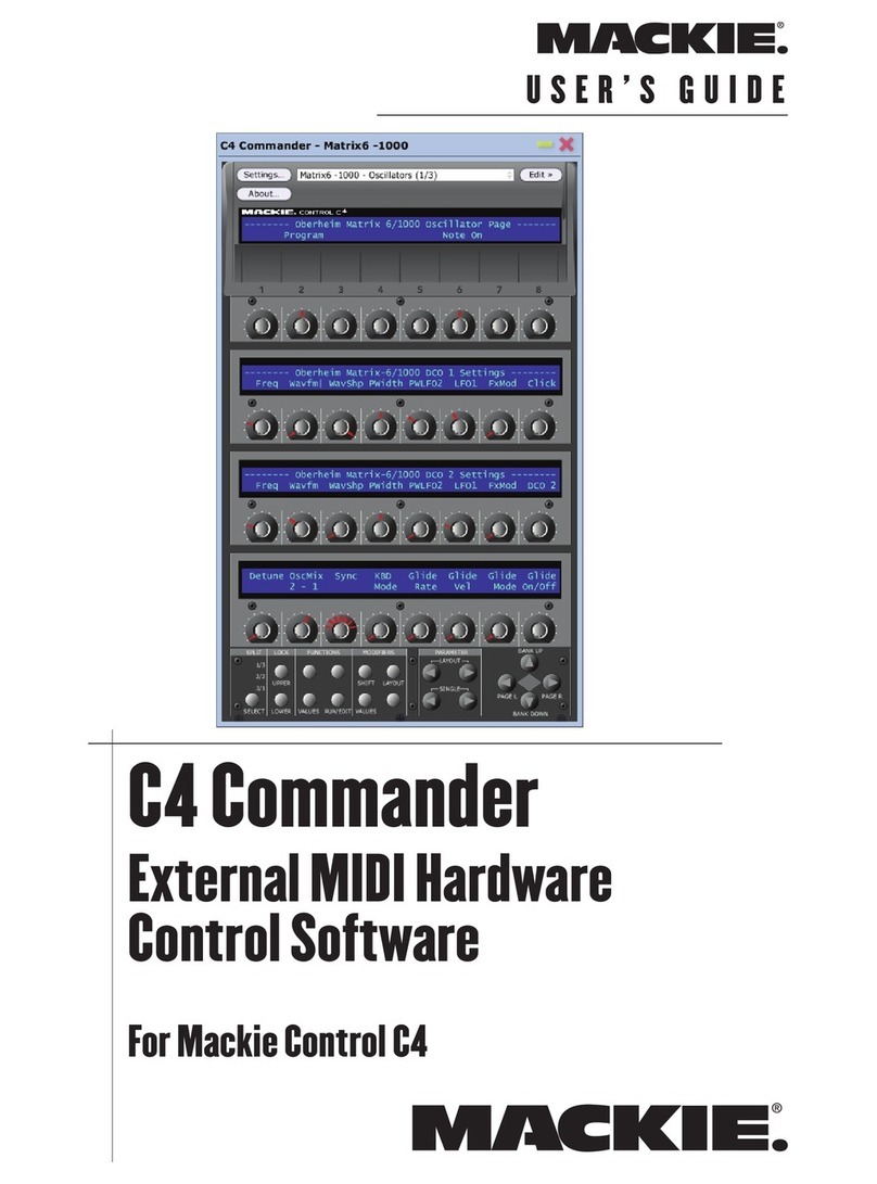
Mackie C4 Commander Owner's manual

P R O G R A M M E R’ S G U I D E
C4 Commander
External MIDI Hardware
Control Software
For Mackie Control C4

Programmer’s Guide
C4 Commander
C4 Commander Programmer's Guide
C4 Commander Files
C4 Commander deals with 2 types of files:
Instrument Definition Files and Layouts.
Instrument Definition Files (.c4i) contain the
parameters that allow C4 Commander to commu-
nicate with a particular MIDI hardware device.
Layout files (.c4l) allow the user to place controls
in a specific order and to relabel control text.
The default Instrument Definition files for the
C4 Commander were designed to provide the
maximum amount of detail for each parameter.
This detail may cause some instrument layouts
to look cluttered or may cause them to be dif-
ficult to read. This can be corrected by simply
using C4 Commander to move and rename pa-
rameters, hence creating an appropriate Layout
file for a particular instrument. This does not
affect the Instrument Definition file, but rather
edits their position within the layout file. As
such, it is possible to create several layouts for
the same instrument, allowing maximum flex-
ibility for a given application.
Instrument Denition Files (.c4i)
There may be instances where editing the In-
struments Definition file is desirable. The main
reason for this is to add ValueText messages to
the definition file, which substitutes descriptive
text in place of numerical values (e.g., Off/On
instead of 0/1).
Another reason for editing the file is to create a
new instrument file either for a MIDI device not
included in the existing Instrument folder, or
based on an existing definition.
Many times when creating a new file for anoth-
er instrument from the same manufacturer, the
manufacturer will use the same SYSEX (System
Exclusive) format (what we call a “schema”)
between multiple devices. In this case, creating
a new instrument may be as simple as chang-
ing the Device ID and the parameter numbers
within the Instrument Definition file. Creating
a new Instrument Definition file from scratch,
however, will require much more work.
Introduction
The C4 Commander User's Guide covers the
general operation of the C4 Commander soft-
ware, while this Programmer's Guide provides
detailed information on customizing the In-
strument Definition files. You might want to
customize an Instrument Definition file simply
to change how a value appears in the display
(ValueText), or you may need to create a new
Instrument Definition file for a MIDI device
that is not included in the Instruments folder
provided with the software. Be sure to check
for Instrument Definition file updates on our
website (in the Settings window, click the
Instruments tab and click on the link at the bot-
tom of the window) to see if a new Instrument
Definition file has been created for the MIDI
device you have.
Contents
C4 Commander Programmer's Guide ---------
Introduction ------------------------------------------
C4 Commander Files --------------------------------
Instrument Denition Files (.c4i) ----------------
New Instrument File Creation ------ 3
Steps in creating a new Instrument le: ---- 3
C4 Commander XML schema ---------------- 3
Basics --------------------------------------3
Syntax -------------------------------------3
Creating a new Instrument Denition ---------4
Masks ------------------------------------ 4
ValueText ------------------------------- 6
Parameters -------------------------------------- 7
Layout les (.c4l) ----------------------------------10
Layout File Format ---------------------------- 11
Console File (.c4s) --------------------------------- 1

Programmer’s Guide
3
C4 Commander
Some Useful Terminology
SYSEX is short for System Exclusive.
This is a MIDI message specific to one
device. The header includes the manufac-
turer's ID and the device ID. A SYSEX message
can be lengthy compared to normal MIDI com-
mands (i.e., MIDI Note or Program Change
messages), because it contains all the data
needed to define the parameters of a device.
Masks are used to hide or ignore specific se-
lected data in a SYSEX message.
HEX is short for hexadecimal, a base-16 num-
ber system that represents every byte as two
consecutive hexadecimal digits (e.g., the binary
number 0011 1111 is represented by the HEX
number 3F).
V-Pot is short for Virtual Potentiometer. These
are the rotary controls on the C4, which are ac-
tually digital encoders but provide the function
of an analog rotary pot.
New Instrument File Creation
What you will need:
Programming experience in XML and C
Familiarity with MIDI SYSEX protocols
An appropriate text editor
Some recommended text editors:
On the PC, use Notepad or WordPad.
On the Mac, use TextEdit.
If you don’t know XML, STOP RIGHT
HERE. The assumption here is that you
already have programmming experience;
hence the title “C4 Commander Programmer's
Guide.”
Steps in creating a new Instrument le:
• Gather the instrument’s SYSEX documen-
tation (see owner’s manual or contact the
synthesizer manufacturer for this informa-
tion).
• Define masks based on the SYSEX mes-
sages used by the instrument.
• Define the parameters to be controlled via
SYSEX.
• Optional — define ValueText messages and
their usage by the instrument.
• Write the instrument file in a text editor.
• Test and debug.
C4 Commander XML schema
Each instrument controlled by the C4 must have
an Instrument Definition file. This is a schema
we have created that is used by the C4 to hook
into functions of that instrument. C4 ships with
definitions of many popular instruments.
Since new instruments are being introduced all
the time, there are two options for obtaining
Instrument Definition files. The first is to wait
for someone else to write the definition, and
the second is to write it yourself. If you are im-
patient and wish to give Instrument Definition
writing a try, the following pages will show you
how.
Basics
Since the format for the schema is XML, ap-
propriate start and end tag syntax (<function>
</function>) is required. Failure to do this will
result in errors when the C4 Commander at-
tempts to load your definition file.
Syntax
Please note the use of the “” marks in the In-
strument Definition file’s source code. These
are not Microsoft Word begin/end quotation
marks, as typed above. These are a text editor’s
straight quotation marks like this: " . If you use
a word processor that substitutes open/closed
(curly) quotes instead of the straight quote
marks, it won't translate correctly, and the C4
Commander will return an error message.

Programmer’s Guide
4
C4 Commander
Creating a new Instrument Denition
Every instrument Definition has a header. If you
wish to create a definition for a new instrument,
you will need to create the following file, or edit
an existing file as a template. The header con-
sists of the following information:
<InstrumentDenition>
This is the tag that
defines the file as an instrument definition file
and as an element contains all data necessary to
communicate with and operate an instrument.
<InstrumentID>
This is the specific instru-
ment’s MIDI ID as assigned by and registered
in the MIDI Manufacturer’s Association (MMA).
A unique ID assigned to each instrument and
stored in HEX.
<ManufacturerName>
Name of instrument man-
ufacturer (e.g., Oberheim).
<ManufacturerID>
This is the Manufacturer’s
MIDI ID as assigned by and registered in the
MIDI Manufacturer’s Association (MMA). A
unique ID assigned to each manufacturer and
stored in HEX.
<DeviceName>
Name of the given instrument
(e.g., Matrix 6). This is displayed in various file
lists and menu trees on the C4 Commander
<DeviceID>
This is the Manufacturer’s Unique
MIDI Device ID as assigned by and registered
in the MIDI Manufacturer’s Association (MMA).
This is unique for each instrument model and
stored in HEX.
Masks
Masks are used to enable the sending and re-
ceiving of complex MIDI messages. Since there
is no “standard” for a MIDI SYSEX message,
masks are the only way to ensure future com-
patibility with the C4 Commander and future
instruments and devices.
<MaskList>
This tag defines the beginning of
the mask list section, and contains a list of all
masks defined for the instrument. An instru-
ment may have several different types of MIDI
SYSEX messages, therefore multiple masks
may be used. Masks are called on a per param-
eter basis, so an LFO message can have one
mask, while a filter message may use another.

Programmer’s Guide
C4 Commander
<Mask>
This tag denotes a single mask element
which specifies all data needed to apply a mask
on a parameter message. This is the beginning
of a single mask’s definition, and each mask
definition segment needs to be terminated by a
corresponding </Mask>
<Name>
The string identifier used to apply a
particular mask on a parameter message (e.g.,
<Param mask="channel">), where Name would
be "channel".
<Byte>
An integer indicating which byte of
the message (one-based, from the left) is to be
masked.
<Bit>
An integer indicating which bit of the
message byte (one-based, from the right) is the
left-most (starting) bit of the mask.
<Size>
The number of bits this mask covers.
<Source>
This value determines where the
mask data is being pulled from. If a parameter
ID is used, the value of that parameter will be
used as the mask data. The following reserved
keywords are used to indicate internal data
sources:
Data — use the current V-Pot value
Channel — use the current V-Pot channel
<SourceBit>
An integer indicating which bit of
the data source (one-based, from the right) is
the left-most (starting) bit of the mask data.

Programmer’s Guide
C4 Commander
ValueText
Valuetext are look-up tables that can be used
for parameters to display text strings instead
of numerical values. An example of this might
be a reverb algorithm that has values from 0-
15. Instead of displaying these values, a far
more intuitive approach would be to display the
words “Plate,” “Arena,” “Lg. hall,” etc., on the
C4’s display. Other examples of where Valuetext
can be useful are:
• LFO waveforms (SINE, SAW, S/H, TRI)
• Sample waveforms (Piano, Sax, vocal,
strings)
• Envelope times (displaying the number of
milliseconds for compressor attack and re-
lease)
• Keyboard modes – mono, poly, omni
• Amplifier selections – British, 2x10, 1x12,
Metal, Jazz
• On/Off messages for portamento, arpeggia-
tor settings, etc.
The Valuetext parameter is a very powerful
and useful tool to simplify and clarify the read-
outs for the C4 controls.
<ValueTextList>
This element contains a list
of all value text lists defined. After you create
this header, begin typing your valuetext state-
ments.
<ValueText name="xxxxxxx">
This element is
used to substitute text in place of a V-Pot nu-
merical value. So instead of seeing 0 and 1 for
a V-Pot value, you can have on and off.
<Text value = "n">VALUETEXT</Text>
A single value text substitution. The tag value
(VALUETEXT) determines what will be substi-
tuted in place of the numerical parameter value.
If a value="n" attribute is present, the tag value
will be substituted for the parameter value n. If
min="a", max="b" attributes are used, the tag
value will be substituted whenever the parame-
ter’s value lies between a and b.
Value Text Example:
<ValueTextList>
<ValueText name="onoff">
<Text value="0">Off</Text>
<Text value="1">On</Text>
</ValueText>
<ValueText name="alg">
<Text value="0">Algorithm 1</Text>
<Text value="1">Algorithm 2</Text>
<Text value="2">Algorithm 3</Text>
<Text value="3">Algorithm 4</Text>
</ValueText>
<ValueText name="MegaOnOff">
<Text min="0" max="63">Off</Text>
<Text min="64" max="127">On</Text>
</ValueText>
</ValueTextList>
A single valuetext can be used for multiple
parameters. In the example above, the “onoff”
valuetext can be referenced to reflect any pa-
rameter that has a 0-1 setting, such as “glide
on/off”, “Layer on/off”, etc.

Programmer’s Guide
7
C4 Commander
<Param>
This tag defines a single parameter el-
ement which specifies all data needed to control
that function. If a mask attribute is present, the
specified mask will be applied to the parameter
message before it is sent to the instrument. If
a valuetext attribute is present, the appropri-
ate substitution will be made to the parameter
value displayed in the C4 commander.
<ParamMask>
This calls out which mask is to
be used for this parameter. It is possible (but
not very efficient) to have a different parameter
mask for each parameter (see <Param> above).
<ParamID>
The ID associated to the given func-
tion. It can be text or numerical. Normally this
should reflect the device manufacturer’s sysex
message parameter ID, so that if one is looking
up “parameter 34 – LFO” from the manufac-
turer’s spec, a simple search for PARAMID 34
would result in the display of this function for
editing.
<FunctionName>
Name of the given function,
e.g., Master volume. The FunctionName is
displayed as the default name in the C4 Com-
mander screen. Since the physical C4 is limited
to displaying only 7-8 characters, the C4 will au-
tomatically truncate this name to fit its display.
It is usually best to keep this parameter as de-
scriptive as possible and use the Layout rename
function to create good-looking onscreen text.
<Message>
The HEX message that will be sent
to the C4 when a V-Pot action is triggered.
<ValueRangeMin>
Minimum value for given
parameter.
<ValueRangeMax>
Maximum value for given
parameter.
Parameters
<ParamTable>
This tag defines the beginning
(and end) of the parameter table. All instru-
ment parameters must be contained withint
the begininning and ending ParamTable tags.
ParamTable contains a list of all parameters
(functions) that the C4 can control. The order
of the parameters determines the correspond-
ing default instrument layout order, so the first
parameter value is placed on the first C4 V-Pot
slot when dragging te entire instrument defini-
tion file onto the C4 Commander’s screen.

Programmer’s Guide
C4 Commander
Instrument Definition Example
<InstrumentDenition>
<ManufacturerName>Yamaha</ManufactureName>
<ManufacturerID>43H</ManufactureID>
<DeviceName>DX100</DeviceName>
<DeviceID>10H 12H</DeviceID>
<MaskList>
<Mask>
<Name>ch</Name>
<Byte>9</Byte>
<Bit>7</Bit>
<Size>4</Size>
<Source>Channel</Source>
<SourceBit>4</SourceBit>
</Mask>
.
.
.
</MaskList>
<ValueTextList>
<ValueText name=”onoff”>
<Text value=”0”>Off</Text>
<Text value=”1”>On</Text>
</ValueText>
<ValueText name="alg">
<Text value="0">Algorithm 1</Text>
<Text value="1">Algorithm 2</Text>
<Text value="2">Algorithm 3</Text>
<Text value="3">Algorithm 4</Text>
</ValueText>
<ValueText name="MegaOnOff">
<Text min="0" max="63">Off</Text>
<Text min="64" max="127">On</Text>
</ValueText>
.
.
.
</ValueTextList>
<ParamTable>
<Param mask=”ch,d1” valuetext=”alg”>
<ParamID>17H</ParamID>
<ParamName>Algorithm</ParamName>
<Message>F0 22 20 33 17 00 00 F7</Message>
<ValueRangeMin>0</ValueRangeMin>
<ValueRangeMax>7</ValueRangeMax>
</Param>

Programmer’s Guide
C4 Commander
<Param>
<ParamID>39H</ParamID>
<ParamName>Amplitude Mod Depth</ParamName>
<Message>F0 22 20 33 39 00 00 F7</Message>
<ValueRangeMin>0</ValueRangeMin>
<ValueRangeMax>99</ValueRangeMax>
</Param>
.
.
.
</ParamTable>
</InstrumentDenition>

Programmer’s Guide
10
C4 Commander
Layout les (.c4l)
A layout is defined as a mapping of all C4 vir-
tual controls to a set of instrument parameters,
i.e., a layout tells the C4 which knob controls
what instrument functions. A layout may span
across multiple pages. Several instruments can
be mapped to from one layout and there is no
restriction to duplicating the same instrument
parameter on two different V-Pots. A user must
create a layout before using the C4 Commander.
The <CustomLayout> element is used in two
ways. First, it is used in each saved layout file
for the purpose of remembering state. Second,
there is a copy of the element in memory that
represents the layout as the user makes chang-
es in real time. When the layout is closed, the
user is prompted to save the current state to a
layout file mentioned earlier.
Layout files are created automatically
when controls are positioned on a C4
Commander screen. As such, there is no
need to manually edit these files. We are provid-
ing the following detail as a point of reference
only, not as an invitation to modify layout files
in a text editor. You could, but really, don’t do it.
Use the C4 commander app to generate layout
files instead.
<CustomLayout>
This element contains all data
necessary for mapping instrument parameters
to the C4.
<LayoutID>
An ID used as a key to uniquely
identify a particular layout. Most likely will be a
generated GUI ID.
<LayoutName>
A name specified by the user for
the layout. This name appears in the top LED
bar of the C4 Commander.
<PageList>
Holds all names of the current
layout’s pages. The order of the child <Page>
elements determines the corresponding page
numbers.
<Page>
A single page name.
<DisplayGroups>
Holds data on all display
groups.
<DisplayGroup>
A single display group. There
are two attributes associated with this element:
bars — setting to true will add horizontal
dashes to the group name
pickets — setting to true will add vertical
separators at the ends of the group name
<StartControl>
The ID of the first control in
the group.
<GroupLength>
The number of V-Pots the dis-
play group spans.
<Control>
This element represents an indi-
vidual mapping from one instrument parameter
to a C4 V-Pot.
<ControlID>
The position of the V-Pot being
mapped to. There are 32 V-Pots per page (if
there is no split), so the 33rd V-Pot would be
the upper leftmost V-Pot on page 2. If a map-
ping is not present for a given V-Pot, it will not
be functional.
<ManufacturerID>
Unique ID assigned to each
manufacturer. Stored in HEX.
<DeviceName>
Name of the given instrument
(e.g., DX100).
<Channel>
The MIDI channel on which the pa-
rameter message will be sent.
<ParamID>
The parameter being mapped.
<Display1>
A short name that will appear in
the LED area above the V-Pot being mapped.
The user can customize this name in the
software. Default value will be the <Instrument-
Name> of the parameter being mapped.
<Display2>
A short name that will appear in
the LED area above the V-Pot being mapped.
The user can customize this name in the soft-
ware. Default value will be the <ParamName>
of the parameter being mapped.
<ValueRangeMin>
Minimum value for given pa-
rameter.
<ValueRangeMax>
Maximum value for given
parameter.

Programmer’s Guide
11
C4 Commander
<RotaryStyle>
Indicates the rotary type for the
V-Pot. Default is 1.
0: Rotary action has no effect.
1: Dot — single LED light ranged from
min to max.
2: Boost/Cut — multiple LEDs starting
at the center top, traveling down the
left or right side. Commonly used for
pan effects.
3: Wrap — similar to Dot except multiple
LEDs fill to the current position.
4: Spread — similar to Boost/Cut except
LEDs on left and right are symmetric.
<RotaryStepSize>
The amount to increment
the parameter value for each step change of the
rotary V-Pot. Default is 1.
<RotaryValue>
The previous value of the pa-
rameter the V-Pot had when the layout was last
used. Default will be half way between the min
and max.
<ToggleResetValue>
The value to set the
param to upon “quick” toggle action of the V-
Pot. Default will be half way between the min
and max.
Layout File Format
<CustomLayout>
<LayoutID>75a1e4445dcd311d</LayoutID>
<LayoutName>line6 podtr</LayoutName>
<Control>
<ControlID>0<ControlID>
<InstrumentID>7e5b1549-c3c6-4f59-a445-23bca5f06b85</InstrumentID>
<ParamID>0</ParamID>
<Channel>1</Channel>
<Display1>Controllers</Display1>
<Display2>Bank Select</Display2>
<ValueRangeMin>0</ValueRangeMin>
<ValueRangeMax>127</ValueRangeMax>
<Value>0</Value>
<ToggleResetValue>64</ToggleResetValue>
<RotaryStyle>1</RotaryStyle>
<ToggleStyle>0</ParamID>
<RotaryStepSize>1</RotaryStepSize>
<RotaryMegaStepSize>0</RotaryMegaStepSize>
<RotaryMicroStepSize>0</RotaryMicroStepSize>
</Control>
<DisplayGroups>
<DisplayGroup bars="true" pickets="true">
<GroupName>Effects</GroupName>
<StartControl>8</StartControl>
<GroupLength>8</GroupLength>
</DisplayGroup>
.
.
</DisplayGroups>
<PageList>
<Page>Line 6 POD Amp</Page>
<Page>FX Deep Editing</Page>
<Page>Page 3</Page>
.
.
</PageList>
</CustomLayout>

Programmer’s Guide
12
C4 Commander
Console File (.c4s)
The Console file contains the default system parameters of the C4 Commander. This file is auto-
matically generated by the C4 Commander and usually requires no editing or enhancement. It is
mentioned here for reference only, and not as an enticement to modify its contents.
“Mackie” and the “Running Man” figure are trademarks or registered trademarks
of LOUD Technologies Inc. All other brand names mentioned are trademarks or
registered trademarks of their respective holders, and are hereby acknowledged.
Part No. SW0371 Rev. A 06/06
© 2006 LOUD Technologies Inc. All Rights Reserved.
R
16220 Wood-Red Road NE • Woodinville, WA 98072 • USA
United States and Canada: 800.898.3211
Europe, Asia, Central and South America: 425.487.4333
Middle East and Africa: 31.20.654.4000
Fax: 425.487.4337 • www.mackie.com
E-mail: [email protected]
Other manuals for C4 Commander
6
Table of contents
Other Mackie Software manuals
Popular Software manuals by other brands

HP
HP dc5700 - Microtower PC Guide

HP
HP StorageWorks 4/8 - SAN Switch release note

Sybase
Sybase Adaptive Server Anywhere Reference

Avocent
Avocent Network Device SPC420 Installer/user guide

Alcatel
Alcatel OmniTouch ACS 7.1.4 Site preparation guide

Novell
Novell IDENTITY MANAGER DRIVER FOR ID PROVIDER 3.6.1 -... manual