Mackie SR1522Z User manual

SR1522z
2-Way active
LOUDSpeakeR SySteM
USeR’S MaNUaL

2
1. Read these instructions.
2. Keep these instructions.
3. Heed all warnings.
4. Follow all instructions.
5. Do not use this apparatus near water.
6. Clean only with dry cloth.
7. Do not block any ventilation openings. Install in accordance with the
manufacturer’s instructions.
8. Do not install near any heat sources such as radiators, heat registers,
stoves, or other apparatus (including amplifiers) that produce heat.
9. Do not defeat the safety purpose of the polarized or grounding-type
plug. A polarized plug has two blades with one wider than the other.
A grounding-type plug has two blades and a third grounding prong.
The wide blade or the third prong are provided for your safety. If the
provided plug does not fit into your outlet, consult an electrician for
replacement of the obsolete outlet.
10.
Protect the power cord from being walked on or pinched particularly at
plugs, convenience receptacles, and the point where they exit from the
apparatus.
11.
Only use attachments/accessories specified by the manufacturer.
12.
Use only with a cart, stand, tripod, bracket, or table specified by the
manufacturer, or sold with the apparatus. When a cart is used, use
caution when moving the cart/apparatus combination to avoid injury
from tip-over.
13.
Unplug this apparatus during lightning storms or when unused for long
periods of time.
14.
Refer all servicing to qualified service personnel. Servicing is required
when the apparatus has been damaged in any way, such as power-
supply cord or plug is damaged, liquid has been spilled or objects have
fallen into the apparatus, the apparatus has been exposed to rain or
moisture, does not operate normally, or has been dropped.
15.
This apparatus shall not be exposed to dripping or splashing, and no
object filled with liquids, such as vases, shall be placed on the apparatus.
16.
This apparatus has been designed with Class-I construction and must
be connected to a mains socket outlet with a protective earthing con-
nection (the third grounding prong).
17.
This apparatus has been equipped with an all-pole, rocker-style AC
mains power switch. This switch is located on the rear panel and
should remain readily accessible to the user.
18.
This apparatus does not exceed the Class A/Class B (whichever is
applicable)
limits for radio noise emissions from digital apparatus as
set out in the radio interference regulations of the Canadian Department
of Communications.
ATTENTION — Le présent appareil numérique n’émet pas de bruits
radioélectriques dépassant las limites applicables aux appareils numériques de
class A/de class B (selon le cas) prescrites dans le réglement sur le brouillage
radioélectrique édicté par les ministere des communications du Canada.
19.
Exposure to extremely high noise levels may cause permanent hearing
loss. Individuals vary considerably in susceptibility to noise-induced
hearing loss, but nearly everyone will lose some hearing if exposed to
sufficiently intense noise for a period of time. The U.S. Government’s
Occupational Safety and Health Administration (OSHA) has specified
the permissible noise level exposures shown in the following chart.
According to OSHA, any exposure in excess of these permissible limits
could result in some hearing loss. To ensure against potentially danger-
ous exposure to high sound pressure levels, it is recommended that all
persons exposed to equipment capable of producing high sound pres-
sure levels use hearing protectors while the equipment is in operation.
Ear plugs or protectors in the ear canals or over the ears must be worn
when operating the equipment in order to prevent permanent hearing
loss if exposure is in excess of the limits set forth here.
IMPORTANT SAFETY INSTRUCTIONS
WARNING — To reduce the risk of fire
or electric shock, do not expose this appara-
tus to rain or moisture.
Duration Per Day Sound Level dBA, Typical
In Hours Slow Response Example
8 90 Duoinsmallclub
6 92
4 95 SubwayTrain
3 97
2 100 Veryloudclassicalmusic
1.5 102
1 105 TamiscreamingatAdrianaboutdeadlines
0.5 110
0.25orless 115 Loudestpartsatarockconcert
PORTABLE CART WARNING
Carts and stands - The
Component should be used
only with a cart or stand
that is recommended by
the manufacturer.
A Component and cart
combination should be
moved with care. Quick
stops, excessive force, and
uneven surfaces may cause
the Component and cart
combination to overturn.
CAUTION AVIS
RISK OF ELECTRIC SHOCK
DO NOT OPEN
RISQUE DE CHOC ELECTRIQUE
NE PAS OUVRIR
CAUTION: TO REDUCE THE RISK OF ELECTRIC SHOCK
DO NOT REMOVE COVER (OR BACK)
NO USER-SERVICEABLE PARTS INSIDE
REFER SERVICING TO QUALIFIED PERSONNEL
ATTENTION: POUR EVITER LES RISQUES DE CHOC
ELECTRIQUE, NE PAS ENLEVER LE COUVERCLE. AUCUN
ENTRETIEN DE PIECES INTERIEURES PAR L'USAGER. CONFIER
L'ENTRETIEN AU PERSONNEL QUALIFIE.
AVIS: POUR EVITER LES RISQUES D'INCENDIE OU
D'ELECTROCUTION, N'EXPOSEZ PAS CET ARTICLE
A LA PLUIE OU A L'HUMIDITE
The lightning flash with arrowhead symbol within an equilateral
triangle is intended to alert the user to the presence of uninsulated
"dangerous voltage" within the product's enclosure, that may be
of sufficient magnitude to constitute a risk of electric shock to persons.
Le symbole éclair avec point de flèche à l'intérieur d'un triangle
équilatéral est utilisé pour alerter l'utilisateur de la présence à
l'intérieur du coffret de "voltage dangereux" non isolé d'ampleur
suffisante pour constituer un risque d'éléctrocution.
The exclamation point within an equilateral triangle is intended to
alert the user of the presence of important operating and maintenance
(servicing) instructions in the literature accompanying the appliance.
Le point d'exclamation à l'intérieur d'un triangle équilatéral est
employé pour alerter les utilisateurs de la présence d'instructions
importantes pour le fonctionnement et l'entretien (service) dans le
livret d'instruction accompagnant l'appareil.

3
CONTENTS
IMPORTANT SAFETY INSTRUCTIONS .................................................................................................2
INTRODUCTION ........................................................................................................................................3
REAR PANEL DESCRIPTION .................................................................................................................... 4
HOOKUP DIAGRAM ..................................................................................................................................5
CONNECTIONS ..........................................................................................................................................5
PLACEMENT ................................................................................................................................................5
Room Acoustics ..................................................................................................................................................................6
THERMAL CONSIDERATIONS ...............................................................................................................6
AC POWER .................................................................................................................................................. 6
SERVICE INFORMATION ..........................................................................................................................7
Troubleshooting ..................................................................................................................................................................7
Repair ....................................................................................................................................................................................8
CARE AND MAINTENANCE ....................................................................................................................8
SR1522z SPECIFICATIONS ........................................................................................................................ 9
SR1522z LIMITED WARRANTY ..............................................................................................................11
Don’t forget to visit our website at www.mackie.com
for more information about this and other Mackie products.
INTRODUCTION
for fans. A tremendous benefit of having the ampli-
fiers located within the loudspeaker cabinet is that the
SR1522z functions as a system, optimizing acoustic,
electronic, and mechanical designs to achieve the high-
est level of performance and value.
The rear mounted amplifier assembly features
separate signal and AC power panels separated by the
heatsink. The signal input panel contains:
• an input XLR and loop-through XLR
• a volume level control
• Power ON indicator
• Signal Present indicator
• Limit indicator
• Thermal Protection indicator
The cabinet is constructed using both 18 mm multi-
layered plywood and pressure injected structural resin.
A carrying handle is integrated into each side for easy
loading and transport.
Thank you for choosing Mackie’s active sound reinforce-
ment loudspeaker systems.
The SR1522z is a high-efficiency, high output, horn-
loaded, 2-way, wide-dispersion, active sound reinforce-
ment system. The SR1522z benefits from the integration
of 400 watts of amplifier power, complete active control
electronics, and precision transducer components.
These elements together form a speaker system with
unprecedented output, resolution, and clarity.
The 1.75-inch neodymium high-frequency compres-
sion driver features a low-distortion optimized symmet-
ric phase plug.
The low frequencies are produced by two high-output
15-inch woofers featuring high-temperature voice coils.
Connecting and setting up the SR1522z is a breeze. It
accepts a line-level signal via a female XLR input jack.
A male XLR Thru jack is provided for daisy-chaining the
signal to additional SR1522z cabinets.
Two built-in power amplifiers provide 100 watts rms
for the high-frequency driver and 400 watts rms for the
low-frequency driver. The amplifier modules sit on a
mammoth aluminum heatsink that eliminates the need
Part No. 0013859 Rev. B 01/08
©2004-2008 LOUD Technologies Inc. All Rights Reserved. Printed in China.

4
REAR PANEL DESCRIPTION
1. MAIN INPUT
This is a female XLR-type connector that
accepts a balanced line-level signal from a
mixing console or other signal source.
2. LOOP OUT
This is a male XLR-type connector that
produces exactly the same signal that is
connected to the MAIN INPUT jack. Use it to
daisy-chain several SR1522z's together off the
same signal source.
3. Level Control
This controls the overall signal level at the input to
the built-in power amplifiers. It ranges from –15 dB to
+5 dB of gain. The center detent is 0 dB (unity gain).
4. Power ON Indicator
When the POWER switch is turned on, and the
linecord is connected to an active AC power supply, this
indicator lights green to let you know that you’re ready
to rock and roll. The cool blue LED on the front of the
cabinet works in the same way.
5. SIGNAL Present Indicator
This LED illuminates whenever there is a signal pres-
ent at the MAIN INPUT connector on the rear panel.
It senses the signal just after the level control, so if
the level control is turned down, the SIGNAL Present
indicator turns off.
6. LIMIT Indicator
The SR1522z has a built-in limiter that prevents the
amplifier outputs from clipping or overdriving
the transducers. The LIMIT indicator lights
when the limiter is activated. It's okay for the
LIMIT indicator to blink occasionally, but if it
blinks frequently or lights continuously, turn
down the level control until the LIMIT indica-
tor only blinks occasionally.
7. THERMAL Indicator
There is also a thermal protection circuit that mon-
itors the internal temperature of the amplifiers and
heatsink. If the temperature should exceed a safe oper-
ating level, this indicator lights and the signal is muted to
allow the amplifiers to cool. When the temperature cools
to a safe level once again, the thermal protection circuit
deactivates and normal operation continues.
Note: Activation of the thermal protection circuit is
an indication that you should take steps to avoid con-
tinued thermal problems. See “Thermal Considerations”
on page 6.
8. POWER Switch
Use this switch to turn the SR1522z on and off. Make
sure the level control is turned down before you turn it
on.
9. AC Receptacle
This is where you connect the AC linecord to provide
AC power to the SR1522z’s built-in power amplifiers.
Plug the linecord into an AC socket properly configured
for your particular model.
SR1522Z
ACTIVE SOUND REINFORCEMENT
SPEAKER SYSTEM
POWER
THERMAL
SIGNAL
LIMIT
LOOP OUT
MAIN INPUT
PARALLEL
0dB
-15 +5
DESIGNED BY MACKOIDS IN WOODINVILLE, WA, USA
COPYRIGHT ©2004 • THE FOLLOWING ARE TRADEMARKS OR
REGISTERED TRADEMARKS OF LOUD TECHNOLOGIES INC.:
"MACKIE", AND THE "RUNNING MAN" FIGURE • PATENT PENDING
WARNING:
THIS SURFACE MAY REACH HIGH TEMPERATURE DURING
STANDARD USE. TO ENSURE PROPER OPERATION ALLOW A MINIMUM OF 6 INS.
OF CLEARANCE FROM THIS SURFACE AND ADEQUATE VENTILATION. TO REDUCE
THE RISK OF ELECTRIC SHOCK DO NOT REMOVE THIS PANEL OR ANY ATTACHED
COMPONENT. NO OPERATOR SERVICEABLE PARTS INSIDE. REFER SERVICING TO
QUALIFIED PERSONNEL. TO REDUCE THE RISK OF FIRE OR ELECTRIC SHOCK, DO NOT
EXPOSE THIS APPLIANCE TO RAIN OR MOISTURE.
RISK OF ELECTRIC SHOCK
DO NOT OPEN
REPLACE WITH THE SAME TYPE FUSE AND RATING.
DISCONNECT SUPPLY CORD BEFORE CHANGING FUSE
UTILISE UN FUSIBLE DE RECHANGE DE MÊME TYPE.
DEBRANCHER AVANT DE REMPLACER LE FUSIBLE
CAUTION
AVIS:
RISQUE DE CHOC ELECTRIQUE — NE PAS OUVRIR
SERIAL NUMBER MANUFACTURING DATE
ON

5
HOOKUP DIAGRAM
Balanced XLR Connectors
There is also a male XLR connector labeled LOOP
OUT. This is also wired according to the above AES
standard.
The LOOP OUT connector allows you to connect
more than one SR1522z to your system. Simply plug the
signal source (i.e., mixer output) into the first MAIN
INPUT jack, and patch that speaker’s LOOP OUT jack
to the next MAIN INPUT jack, and so on, daisy-chaining
multiple speakers.
CONNECTIONS
DAISY-CHAINING MULTIPLE SR1522z's
The SR1522z has one female XLR input that accepts
a balanced line-level signal. When connecting a balanced
signal, be sure it’s wired per AES (Audio Engineering
Society) standards:
XLR
Hot (+) Pin 2
Cold (–) Pin 3
Shield (Ground)
Pin 1
The LOOP OUT jack is wired straight from the MAIN
INPUT connector — there is no electronic circuitry
between — so the signal coming out of the LOOP OUT
jack is exactly the same as the signal going in.
PLACEMENT
The SR1522z speaker is designed to sit on the floor or
stage.
WARNING: The cabinet has no rig-
ging points and is not suitable for rig-
ging. NEVER attempt to suspend the
SR1522z by its handles. The SR1522z
should never be pole-mounted.
You can create a horizontal array by placing the cabi-
nets side-by-side. However, you should have a good un-
derstanding of the relationship between the splay angle
(the angle between the facing sides of the cabinets),
the on-axis power, and frequency cancellation effects
between cabinets.
When two cabinets are placed side-by-side, the actual
splay angle is 20º (determined by a 10º angle on each
cabinet side). As the splay angle increases toward the
angle of horizontal coverage (90º for the SR1522z), the
on-axis power decreases, but the frequency response
becomes smoother as the comb-filtering effects (caused
by the interaction in the area of double-coverage)
decrease.
As with any powered components,
protect them from moisture. If you
are setting them up outdoors, make
sure they are under cover if you
expect rain.
SR1522Z
ACTIVE SOUND REINFORCEMENT
SPEAKER SYSTEM
POWER
THERMAL
SIGNAL
LIMIT
LOOP OUT
MAIN INPUT
PARALLEL
0dB
-15 +5
DESIGNEDBYMACKOIDSIN WOODINVILLE,WA, USA
COPYRIGHT©2004• THE FOLLOWINGARETRADEMARKSOR
REGISTEREDTRADEMARKSOFLOUD TECHNOLOGIESINC.:
"MACKIE",AND THE "RUNNINGMAN" FIGURE• PATENTPENDING
SR1522Z
ACTIVE SOUND REINFORCEMENT
SPEAKER SYSTEM
POWER
THERMAL
SIGNAL
LIMIT
LOOP OUT
MAIN INPUT
PARALLEL
0dB
-15 +5
DESIGNEDBYMACKOIDSIN WOODINVILLE,WA, USA
COPYRIGHT©2004• THE FOLLOWINGARETRADEMARKSOR
REGISTEREDTRADEMARKSOFLOUD TECHNOLOGIESINC.:
"MACKIE",AND THE "RUNNINGMAN" FIGURE• PATENTPENDING
SR1522Z
ACTIVE SOUND REINFORCEMENT
SPEAKER SYSTEM
POWER
THERMAL
SIGNAL
LIMIT
LOOP OUT
MAIN INPUT
PARALLEL
0dB
-15 +5
DESIGNEDBYMACKOIDSIN WOODINVILLE,WA, USA
COPYRIGHT©2004• THE FOLLOWINGARETRADEMARKSOR
REGISTEREDTRADEMARKSOFLOUD TECHNOLOGIESINC.:
"MACKIE",AND THE "RUNNINGMAN" FIGURE• PATENTPENDING
SR1522Z
ACTIVE SOUND REINFORCEMENT
SPEAKER SYSTEM
POWER
THERMAL
SIGNAL
LIMIT
LOOP OUT
MAIN INPUT
PARALLEL
0dB
-15 +5
DESIGNEDBYMACKOIDSIN WOODINVILLE,WA, USA
COPYRIGHT©2004• THE FOLLOWINGARETRADEMARKSOR
REGISTEREDTRADEMARKSOFLOUD TECHNOLOGIESINC.:
"MACKIE",AND THE "RUNNINGMAN" FIGURE• PATENTPENDING
Mixer or
Preamplifier
Right
Line level
Output
Left
Line level
Output
To Next
Speaker
To Next
Speaker
1202-VLZPRO

6
Room Acoustics
The SR1522z loudspeakers are designed to sound as
neutral as possible; that is, to reproduce the input signal
as accurately as possible.
Room acoustics play a crucial role in the overall per-
formance of a sound system. Here are some additional
placement tips to help overcome some typical room
problems that might arise:
• Avoid placing loudspeakers in the corners of a
room. This increases the low frequency output and
can cause the sound to be muddy and indistinct.
• Avoid placing loudspeakers against a wall. This, too,
increases the low frequency output, though not as
much as corner placement. However, if you do need
to reinforce the low frequencies, this is a good way
to do it.
• Avoid placing the speakers directly on a hollow
stage floor. A hollow stage can resonate at certain
frequencies, causing peaks and dips in the fre-
quency response of the room. It’s better to place the
loudspeakers on a sturdy table or stand designed to
handle the weight of the SR1522z.
•
Position the loudspeakers so the high-frequency
drivers are 2 to 4 feet above ear level for the audience
(make allowances for a standing/dancing in the aisles
audience). High frequencies are highly directional
and tend to be absorbed much easier than lower
frequencies. By providing direct line-of-sight from the
loudspeakers to the audience, you increase the over-
all brightness and intelligibility of the sound system.
•
Highly reverberant rooms, like many gymnasiums
and auditoriums, are a nightmare for sound system
intelligibility. Multiple reflections off the hard walls,
ceiling, and floor play havoc with the sound. Depend-
ing on the situation, you may be able to take some
steps to minimize the reflections, such as putting
carpeting on the floors, closing draperies to cover
large glass windows, or hanging tapestries or other
materials on the walls to absorb some of the sound.
However, in most cases, these remedies are not possi-
ble or practical. So what do you do? Making the sound
system louder generally doesn’t work because the
reflections become louder, too. The best approach is to
provide as much direct sound coverage to the audience
as possible. The farther away you are from the speaker,
the more prominent will be the reflected sound.
Use more speakers strategically placed so they are
closer to the back of the audience. If the distance
between the front and back speakers is more than
about 100 feet, you should use a delay processor to
time-align the sound. (Since sound travels about
1 foot per millisecond, it takes about 1/10 of a
second to travel 100 feet.)
THERMAL CONSIDERATIONS
The SR1522z has two powerful built-in amplifiers
capable of producing a combined 500 watts of power.
As amplifiers produce heat, it is important to dissipate
the heat as quickly as possible. This results in increased
reliability and longevity for the amplifier.
The amplifier module is mounted on a large heatsink,
which is cooled by convection where cool air is drawn
through it’s fins, carrying the heat away. In order for this
convection cooling to work efficiently, it is important
to provide adequate airspace behind the loudspeaker.
When you position the SR1522z, we recommend leaving
at least six inches of air space behind it.
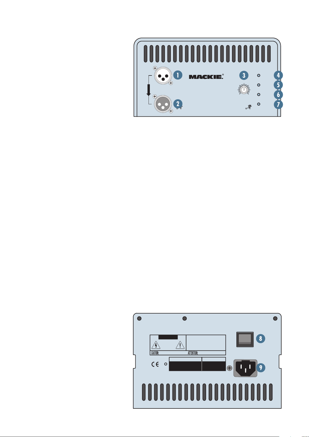
In the unlikely event of the amplifier overheating, a
built-in thermal switch will activate, which mutes the
signal and lights the THERMAL LED. When the amplifi-
er has cooled down to a safe operating temperature, the
thermal switch resets itself, and the SR1522z resumes
normal operation.
If the thermal switch activates frequently, try turning
down the level control a notch or two on the mixing con-
sole (or the back of the SR1522z) to avoid overheating
the amplifier.
If the temperature in the room is too high, it could
cause the amplifier to overheat. In this case, you should
try aiming a fan at the rear panel to move more air
through the heatsink fins.
AC POWER
Be sure the SR1522z is plugged into an outlet that
is able to supply the correct voltage specified for your
model. If the voltage should drop below 97% of the spec-
ified line voltage, the built-in amplifiers will no longer
be able to supply rated power. (They will continue to
operate down to 80% of the rated line voltage, but won’t
reach full power, resulting in lower headroom.)
Be sure the electrical service can supply enough am-
perage for all the components connected to it.
We recommend that a stiff (robust) supply of AC
power be used because the amplifiers place high cur-
rent demands on the AC line. The more power that is
available on the line, the louder the speakers will play
and the more peak output power will be available for
cleaner, punchier bass. A suspected problem of “poor
bass performance” is often caused by a weak AC supply
to the amplifiers.
Never remove the ground pin on
the power cord of the SR1522z or
any other component. This is very
dangerous.

7
Poor sound
• Is it loud and distorted? Make sure that you’re not
overdriving a stage in the signal chain. Verify that
all level controls are set properly.
• Is the input connector plugged completely into the
jack? Be sure all connections are secure. It’s a good
idea to periodically clean all electrical connections
with a non-lubricating electrical contact cleaner.
Noise
• Make sure all connections to the active loudspeak-
ers are good and sound.
• Make sure none of the signal cables are routed near
AC cables, power transformers, or other EMI-induc-
ing devices.
• Is there a light dimmer or other SCR-based device
on the same AC circuit as the SR1522z? Use an AC
line filter or plug the SR1522z into a different AC
circuit.
Hum
• Try disconnecting the cable connected to the MAIN
INPUT jack. If the noise disappears, it could be
a “ground loop,” rather than a problem with the
SR1522z. Try some of the following troubleshooting
ideas:
◊Use balanced connections throughout your
system for the best noise rejection.
◊Whenever possible, plug all the audio equip-
ment’s linecords into outlets which share a common
ground. The distance between the outlets and the
common ground should be as short as possible.
SERVICE INFORMATION
If you think your Mackie product has a problem,
please check out the following troubleshooting tips and
do your best to confirm the problem. Visit the Support
section of our website (www.mackie.com/support)
where you will find lots of useful information such as
FAQs, documentation, and user forums. You may find
the answer to the problem without having to send your
Mackie product away.
Troubleshooting
No power
• Our favorite question: Is it plugged in? Make sure
the AC outlet is live (check with a tester or lamp).
• Our next favorite question: Is the POWER switch
on? If not, try turning it on.
• Is the POWER LED on the rear panel glowing
green? If not, make sure the AC outlet is live. If so,
refer to “No sound” below.
• The internal AC line fuse may be blown. This is not
a user serviceable part. If you suspect the AC line
fuse is blown, please see the "Repair" section next.
No sound
• Is the input level control for the input source
turned all the way down? Verify that all the volume
controls in the system are properly adjusted.
• Is the signal source working (and making union
scale)? Make sure the connecting cables are in good
repair and securely connected at both ends. Make
sure the output volume (gain) control on the mixing
console is turned up sufficiently to drive the inputs of
the speaker.
• Make sure the mixer does not have a Mute on or a
Processor loop engaged. If you find something like
this, make sure the volume/gain is turned down
before disengaging the offending switch.
• Is the THERMAL indicator lit red on the rear panel?
Make sure there is at least six inches of free space
behind the SR1522z.
Poor bass performance
• Check the polarity of the connections between the
mixer and the loudspeakers. You may have your
positive and negative connections reversed at one
end of one cable, causing one loudspeaker to be
out-of-phase.

8
Repair
For warranty repair or replacement, refer to the
warranty information on page 11.
Non-warranty repair for Mackie products is avail-
able at a factory-authorized service center. To locate
your nearest service center, visit www.mackie.com,
click “Support” and select “Locate a Service Cen-
ter.” Service for Mackie products living outside the
United States can be obtained through local dealers
or distributors.
If you do not have access to our website, you can
call our Tech Support department at 1-800-898-3211,
Monday-Friday, 7 am to 5 pm Pacific Time, to explain
the problem. Tech Support will tell you where the
nearest factory-authorized service center is located in
your area.
CARE AND MAINTENANCE
Your Mackie loudspeakers will provide many years of
reliable service if you follow these guidelines:
Avoid exposing the loudspeakers to
moisture. If they are set up out-
doors, be sure they are under cover
if you expect rain.
• Avoid exposure to extreme cold (below freezing
temperatures). If you must operate the loud-
speakers in a cold environment, warm up the voice
coils slowly by sending a low-level signal through
them for about 15 minutes prior to high-power
operation.
• Use a slighty damp cloth with a mild soap solution
to clean the cabinets. Only do this when the power
is turned off. Avoid getting moisture into any of the
openings of the cabinet, particularly where the driv-
ers are located.
Need Help?
You can reach a technical support representative
Monday through Friday
from 7 AM to 5 PM PST at:
1-800-898-3211
After hours, visit www.mackie.com and click Support,
or email us at: techmail@mackie.com

9
SR1522z SPECIFICATIONS
Acoustic Performance
Frequency Range (–10 dB)
43 Hz–20 kHz
Frequency Response (–3 dB)
56 Hz–18 kHz
Horizonal Coverage Angle (–6 dB)
90º averaged 2 kHz to 10 kHz
Vertical Coverage Angle (–6 dB)
40º averaged 2 kHz to 10 kHz
Directivity Factor; DI (Q)
12.1 (16.4) averaged 2k Hz to 10 kHz
Max SPL long-term 130 dB @ 1m
Max SPL peak 133 dB @ 1m
Crossover Point 1300 Hz
Input/Output
Input Type Female XLR Balanced/Unbalanced
Input Impedance 50 kohms balanced
Loop-Through Male XLR Balanced/Unbalanced
(parallel with input)
Level Control Rotating knob (–15 to +5 dB),
center detent at 0 dB
High-Frequency Section
Voice Coil Diameter 1.75 in/44 mm
Horn Exit Diameter 1.0 in/25 mm
Phase Plug Optimized geometry
Diaphragm Material Titanium
Magnet Material Ferrite
Low-Frequency Section
Number of Drivers 2
Woofer Diameter 15.0 in/381 mm
Voice Coil Diameter 2.5 in/63 mm
Diaphragm Material Epoxy-reinforced cellulose
Magnet Material Ferrite
Power Amplifiers
Low-Frequency Power Amplifier
Rated Power 400 watts rms
Rated THD < 0.03%
Design Class G, Hybrid
High-Frequency Power Amplifier
Rated Power 100 watts rms
Rated THD < 0.03%
Design Class AB
Line Input Power
US 120V, 60Hz
Recommended Amperage Service: 13 amps
Europe 230V, 50Hz
Recommended Amperage Service: 7 amps
AC Connector 3-pin IEC 250 VAC
Safety Features
Input Protection Low frequency dynamic bass
protection, rms limiting, power
supply and amplifier thermal
protection
Display LEDs Power ON, Signal Present, Limit,
Thermal (cool down auto-reset)
Construction Features
Basic Design Trapezoidal, 10º side angles
Material 18 mm multi-layered plywood,
resin end caps
Finish Wear-resistant textured black
PVC vinyl
Handles
One on each side, one top, one bottom
Grille Perforated metal with weather-
resistant coating
Physical Properties
Height 50.0 in/127.0 cm
Front Width 19.1 in/48.5 cm
Rear Width 13.9 in/35.3 cm
Depth 18.1 in/46.0 cm
Weight 132 lb/60 kg
Mounting Methods Floor mount only.
The SR1522z should never be pole-mounted.
The cabinet has no rigging points and is not
suitable for flying. Never attempt to suspend the
cabinet by its handles.
Disclaimer
Since we are always striving to make our products better by in-
corporating new and improved materials, components, and manufac-
turing methods, we reserve the right to change these specifications
at any time without notice.
“Mackie” and the “Running Man” figure are registered trademarks
of LOUD Technologies Inc.
All other brand names mentioned are trademarks or registered
trademarks of their respective holders, and are hereby acknowledged.
©2004-2008 LOUD Technologies Inc.
All Rights Reserved.
R

10
SR1522z Beamwidth vs. Frequency SR1522z Directivity vs. Frequency
SR1522z Dimensions
SR1522z Frequency Response On-Axis
WARNING:
THISSURFACEMAYREACH HIGH TEMPERATURE DURING
STANDARDUSE.TO ENSURE PROPER OPERATION ALLOW A MINIMUM OF 6 INS.
OFCLEARANCEFROMTHIS SURFACE AND ADEQUATE VENTILATION. TOREDUCE
THERISKOFELECTRIC SHOCK DO NOT REMOVE THIS PANEL OR ANY ATTACHED
COMPONENT.NOOPERATOR SERVICEABLE PARTS INSIDE. REFERSERVICINGTO
QUALIFIEDPERSONNEL.TO REDUCE THE RISK OF FIRE OR ELECTRIC SHOCK, DO NOT
EXPOSETHISAPPLIANCETO RAIN OR MOISTURE.
RISKOFELECTRICSHOCK
DONOTOPEN
REPLACEWITHTHESAME TYPE FUSE AND RATING.
DISCONNECTSUPPLYCORDBEFORE CHANGING FUSE
UTILISEUNFUSIBLEDE RECHANGE DE MÊME TYPE.
DEBRANCHERAVANTDEREMPLACER LE FUSIBLE
CAUTION
AVIS:
RISQUEDECHOCELECTRIQUE — NE PAS OUVRIR
SERIALNUMBER MANUFACTURINGDATE
ON
SR1522Z
ACTIVE SOUND REINFORCEMENT
SPEAKER SYSTEM
POWER
THERMAL
SIGNAL
LIMIT
LOOPOUT
MAININPUT
PARALLEL
0dB
-15 +5
DESIGNEDBYMACKOIDSINWOODINVILLE,WA,USA
MANUFACTUREDINCHINA•FABRIQUEEN CHINE• COPYRIGHT©2004 • THE
FOLLOWINGARETRADEMARKSORREGISTEREDTRADEMARKSOFMACKIEDESIGNS
INC.:"MACKIE",ANDTHE "RUNNINGMAN" FIGURE• PATENTPENDING
50.0 in/
127.0 cm
13.9 in/
35.3 cm
18.1 in/
46.0 cm
19.1 in/
48.5 cm
19.1 in/
48.5 cm
110
100
90
80
70
1/3 Octave Response
dB SPL @ 2.83 V
SR1522z Frequency Response On-Axis
Frequency (Hz)
20 100 1000 10000 20000
Horizontal / Vertical
Frequency (Hz)
20 100 1000 10000 20000
SR1522z Beamwidth vs. Frequency
Beamwidth Degrees
360
300
240
180
120
60
0
Frequency (Hz)
20 100 1000 10000 20000
SR1522z Directivity vs. Frequency
100
10
1
Directivity Factor (Q)
Directivity Index (DI), dB
20
10
0

11
A. LOUD Technologies Inc. warrants all materials,
workmanship and proper operation of this product for a period
of three years from the original date of purchase. You may
purchase an additional 24-month Extended Warranty (for a
total of 60 months of coverage). Visit our website and follow
the “Product Registration” links for details (www.mackie.com).
If any defects are found in the materials or workmanship or
if the product fails to function properly during the applicable
warranty period, LOUD Technologies, at its option, will repair
or replace the product.
This warranty applies only to equipment
sold and delivered within the U.S. and Canada by LOUD
Technologies Inc. or its authorized dealers.
B. For faster processing (not to mention a free gift), register
online or mail in the product registration card.
C. Unauthorized service, repairs, or modification of Mackie
products will void this warranty. To obtain repairs or
replacement under warranty, you must have a copy of your
sales receipt from the authorized Mackie dealer where you
purchased the product. It is necessary to establish purchase
date and determine whether your Mackie product is within
the warranty period.
D. To obtain warranty repair or replacement:
1.
Call Mackie Technical Support at 800/898-3211, 7 AM
to 5 PM Monday through Friday (Pacific Time) to get
authorization for repair or replacement. Alternately, go to
the Mackie website, click “Support” (www.mackie.com/
support), and follow the instructions for reporting a warranty
issue and submitting a request for an advance replacement.
2.
Advance Replacement: Mackie will ship a replacement
unit to you along with an invoice for the suggested
retail price of the replacement unit. You must return the
defective unit immediately to cancel the invoice. If you do
not return the defective unit within 30 days, you must pay
the full amount stated in the invoice to satisfy your debt.
3. Repair: When you call Mackie Technical Support,
explain the problem and obtain a Service Request
Number. Have your Mackie product’s serial number
ready. You must have a Service Request Number before
you can obtain factory-authorized service.
• Pack the product in its original shipping carton. Also
include a note explaining exactly how to duplicate the
problem, a copy of the sales receipt with price and date
showing, your daytime phone number and return street
address (no P.O. boxes or route numbers, please!), and
the Service Request Number. If we cannot duplicate the
problem or establish the starting date of your Limited
Warranty, we may, at our option, charge for service time
and parts.
• Ship the product in its original shipping carton,
freight prepaid to the authorized service center. Write
the Service Request Number in BIG PRINT on top of
the box. The address of your closest authorized service
center will be given to you by Technical Support, or it
may be obtained from our website. Once it’s repaired,
the authorized service center will ship it back by ground
shipping, pre-paid (if it qualified as a warranty repair).
Note: Under the terms of the warranty, you must ship
or drop-off the unit to an authorized service center.
The return ground shipment is covered for those units
deemed by us to be under warranty.
Note: You must have a sales receipt from an authorized
Mackie dealer for your unit to be considered for
warranty repair.
IMPORTANT: Make sure that the Service Request Number
is plainly written on the shipping carton. No receipt, no
warranty service.
E. LOUD Technologies reserves the right to inspect any
products that may be the subject of any warranty claims before
repair or replacement is carried out. LOUD Technologies may,
at our option, require proof of the original date of purchase in
the form of a dated copy of the original dealer’s invoice or sales
receipt. Final determination of warranty coverage lies solely
with LOUD Technologies.
F. Any products returned to one of the LOUD Technologies
factory-authorized service centers, and deemed eligible
for repair or replacement under the terms of this warranty
will be repaired or replaced. LOUD Technologies and its
authorized service centers may use refurbished parts for repair
or replacement of any product. Products returned to LOUD
Technologies that do not meet the terms of this Warranty
will not be repaired unless payment is received for labor,
materials, return freight, and insurance. Products repaired
under warranty will be returned freight prepaid by LOUD
Technologies to any location within the boundaries of the USA
or Canada.
G. LOUD Technologies warrants all repairs performed
for 90 days or for the remainder of the warranty period.
This warranty does not extend to damage resulting from
improper installation, misuse, neglect or abuse, or to exterior
appearance. This warranty is recognized only if the inspection
seals and serial number on the unit have not been defaced or
removed.
H. LOUD Technologies assumes no responsibility for the
timeliness of repairs performed by an authorized service
center.
I. This warranty is extended to the original purchaser. This
warranty may be transferred to anyone who may subsequently
purchase this product within the applicable warranty period
for a nominal fee. A copy of the original sales receipt is
required to obtain warranty repairs or replacement.
J. This is your sole warranty. LOUD Technologies does not
authorize any third party, including any dealer or sales
representative, to assume any liability on behalf of LOUD
Technologies or to make any warranty for LOUD Technologies
Inc.
K. THE WARRANTY GIVEN ON THIS PAGE IS THE SOLE
WARRANTY GIVEN BY LOUD TECHNOLOGIES INC.
AND IS IN LIEU OF ALL OTHER WARRANTIES, EXPRESS
AND IMPLIED, INCLUDING THE WARRANTIES OF
MERCHANTABILITY AND FITNESS FOR A PARTICULAR
PURPOSE. THE WARRANTY GIVEN ON THIS PAGE
SHALL BE STRICTLY LIMITED IN DURATION TO THREE
YEARS FROM THE DATE OF ORIGINAL PURCHASE
FROM AN AUTHORIZED MACKIE DEALER. UPON
EXPIRATION OF THE APPLICABLE WARRANTY PERIOD,
LOUD TECHNOLOGIES INC. SHALL HAVE NO FURTHER
WARRANTY OBLIGATION OF ANY KIND. LOUD
TECHNOLOGIES INC. SHALL NOT BE LIABLE FOR ANY
INCIDENTAL, SPECIAL, OR CONSEQUENTIAL DAMAGES
THAT MAY RESULT FROM ANY DEFECT IN THE MACKIE
PRODUCT OR ANY WARRANTY CLAIM. Some states do
not allow exclusion or limitation of incidental, special, or
consequential damages or a limitation on how long warranties
last, so some of the above limitations and exclusions may not
apply to you. This warranty provides specific legal rights and
you may have other rights which vary from state to state.
Please keep your sales receipt in a safe place.
SR1522z Limited Warranty

16220 Wood-Red Road NE • Woodinville, WA 98072 • USA
United States and Canada: 800.898.3211
Europe, Asia, Central and South America: 425.487.4333
Middle East and Africa: 31.20.654.4000
Fax: 425.487.4337 • www.mackie.com
E-mail: [email protected]
Other manuals for SR1522Z
1
Table of contents
Other Mackie Speakers manuals

Mackie
Mackie C200 User manual

Mackie
Mackie HR624 MK2 User manual

Mackie
Mackie TH-12A User manual

Mackie
Mackie SRM 450 User manual

Mackie
Mackie MR524 User manual

Mackie
Mackie DLM8 User manual

Mackie
Mackie TH-12A Quick start guide

Mackie
Mackie SP400C Manual

Mackie
Mackie Thump12 User manual

Mackie
Mackie SRM450v2 User manual

Mackie
Mackie SRM450v3 User manual

Mackie
Mackie HD1221 User manual

Mackie
Mackie S512 Installation guide

Mackie
Mackie SRM210 V-Class User manual

Mackie
Mackie DLM12 User manual

Mackie
Mackie S500 Series User manual

Mackie
Mackie Creative Reference CR3 User manual

Mackie
Mackie C300z User manual

Mackie
Mackie Monitor Series MR3STK User manual

Mackie
Mackie HR824 User manual