DLM12S Powered Subwoofer
8
DLM12S Powered Subwoofer
Large Club System
100-240V
50-60Hz 250W
POWER
THISDEVICECOMPLIES WITH PART 15 OF THE FCC RULES FOR
THEU.S.AND ICES-003, FOR CANADA. OPERATION IS SUBJECT TO
THEFOLLOWINGTWO CONDITIONS: (1) THIS DEVICE MAYNOT
CAUSEHARMFULINTERFERENCE, AND (2) THIS DEVICE MUST
ACCEPTANYINTERFERENCE RECEIVED,INCLUDING INTERFERENCE
THATMAYCAUSEUNDESIRED OPERATION.
REVISION
SERIALNUMBER
WARNING:
AVIS:RISQUEDE CHOC ELECTRIQUE - NE PAS OUVRIR
TOREDUCETHE RISK OF FIRE OR ELECTRIC
SHOCK,DONOT EXPOSE THIS EQUIPMENT TO RAIN OR
MOISTURE.DONOT REMOVE COVER. NO USER SERVICEABLE
PARTSINSIDE.REFER SERVICING TO QUALIFIED PERSONNEL.
RISKOFELECTRIC SHOCK
DONOTOPEN
AVIS:
N'OUVREZPAS LA COUVERTURE. N'EXPOSEZ
PASCETÉQUIPEMENT À LA PLUIE OU À L'HUMIDITÉ.
INPUTS FULLRANGEHIGHPASS
A
B
A
B
STEREO
MONO
NORMAL
INVERT
A
MEMSYS21
BASS+2
TREBLE+2
AUX
LEVEL
2000WDigital Subwoofer
100-240V
50-60Hz 250W
POWER
THISDEVICECOMPLIES WITH PART 15 OF THE FCC RULES FOR
THEU.S.AND ICES-003, FOR CANADA. OPERATION IS SUBJECT TO
THEFOLLOWINGTWO CONDITIONS: (1) THIS DEVICE MAYNOT
CAUSEHARMFULINTERFERENCE, AND (2) THIS DEVICE MUST
ACCEPTANYINTERFERENCE RECEIVED,INCLUDING INTERFERENCE
THATMAYCAUSEUNDESIRED OPERATION.
REVISION
SERIALNUMBER
WARNING:
AVIS:RISQUEDE CHOC ELECTRIQUE - NE PAS OUVRIR
TOREDUCETHE RISK OF FIRE OR ELECTRIC
SHOCK,DONOT EXPOSE THIS EQUIPMENT TO RAIN OR
MOISTURE.DONOT REMOVE COVER. NO USER SERVICEABLE
PARTSINSIDE.REFER SERVICING TO QUALIFIED PERSONNEL.
RISKOFELECTRIC SHOCK
DONOTOPEN
AVIS:
N'OUVREZPAS LA COUVERTURE. N'EXPOSEZ
PASCETÉQUIPEMENT À LA PLUIE OU À L'HUMIDITÉ.
INPUTS FULLRANGEHIGHPASS
A
B
A
B
STEREO
MONO
NORMAL
INVERT
A
MEMSYS21
2000WDigital Subwoofer
BASS+2
TREBLE+2
AUX
LEVEL
R
L
100-240V
50-60Hz 250W
POWER
Line
Mic
Ch1
Mix
THISDEVICECOMPLIES WITH PART 15 OF THE FCC RULES FOR
THEU.S.AND ICES-003, FOR CANADA. OPERATION IS SUBJECT TO
THEFOLLOWINGTWO CONDITIONS: (1) THIS DEVICE MAY NOT
CAUSEHARMFULINTERFERENCE, AND (2) THIS DEVICE MUST
ACCEPTANYINTERFERENCE RECEIVED, INCLUDINGINTERFERENCE
THATMAYCAUSEUNDESIRED OPER ATION.
REVISION
SERIALNUMBER
WARNING:
AVIS:RISQUEDE CHOC ELECTRIQUE - NE PAS OUVRIR
TOREDUCETHE RISK OF FIRE OR ELECTRIC
SHOCK,DONOT EXPOSE THIS EQUIPMENT TO RAIN OR
MOISTURE.DONOT REMOVE COVER. NO USER SERVICEABLE
PARTSINSIDE.REFER SERVICING TO QUALIFIED PERSONNEL.
1THRU2
TRS=
TRS=Line
XLR
RISKOFELECTRIC SHOCK
DONOTOPEN
AVIS:
N'OUVREZPAS LA COUVERTURE. N'EXPOSEZ
PASCETÉQUIPEMENT À LA PLUIE OU À L'HUMIDITÉ.
MEMSYS21
2000WDigital Loudspeaker
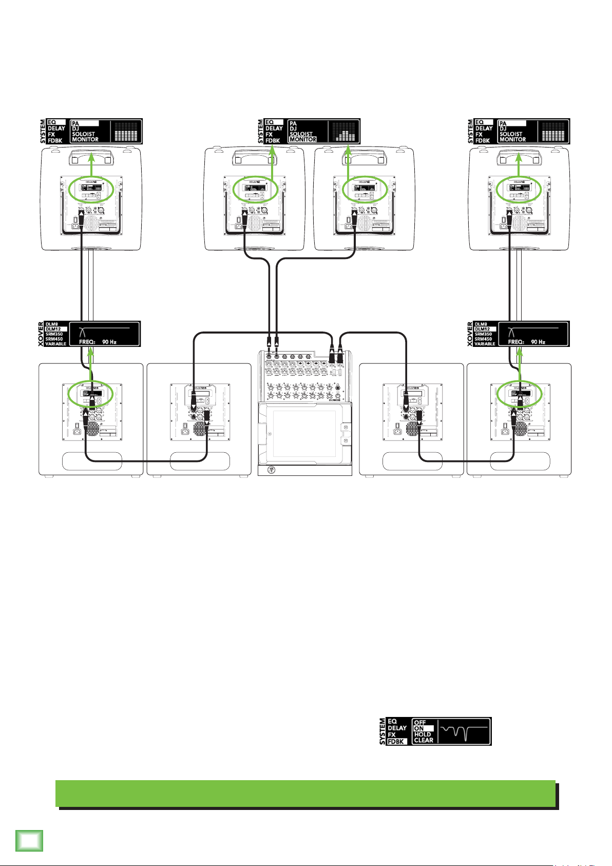
Hookup Diagrams continued...
Here’s how to set up a large club system using all Mackie gear. In this example, the L/R outputs of
a Mackie DL1608 mixer are connected directly to the channel A inputs of two DLM12S subwoofers.
The channel A full range outputs of these two DLM12S subwoofers are connected directly to the channel
A inputs of another set of DLM12S subwoofers. Talk about beefy low end, that’s 8000 watts, yo!
And we’ve only connected the subs.
The channel A high pass outputs of the last two DLM12S subwoofers are connected directly to the
channel 1 inputs of the main pair of DLM loudspeakers. Be sure the mic/line switch is OUT.
Or be ready to be blasted with an additional 30 dB! Select the DLM12 crossover on each DLM12S
for a perfectly matched system tuning.
DLM loudspeakers are also perfect for using as stage monitors. Simply connect a cable from an aux
send to the channel 1 input of a DLM loudspeaker. For the aux to monitor output, you will want to set
a speaker mode, described in detail in the DLM loudspeaker manual. Since these are monitors, select the
appropriately named monitor speaker mode.
Select PA speaker mode for the main loudspeakers. You will want
to turn the feedback eliminator ON on all four DLM loudspeakers,
as described in the DLM loudspeaker manual.