1
2
3
4
5
6
7
8
9
10
11
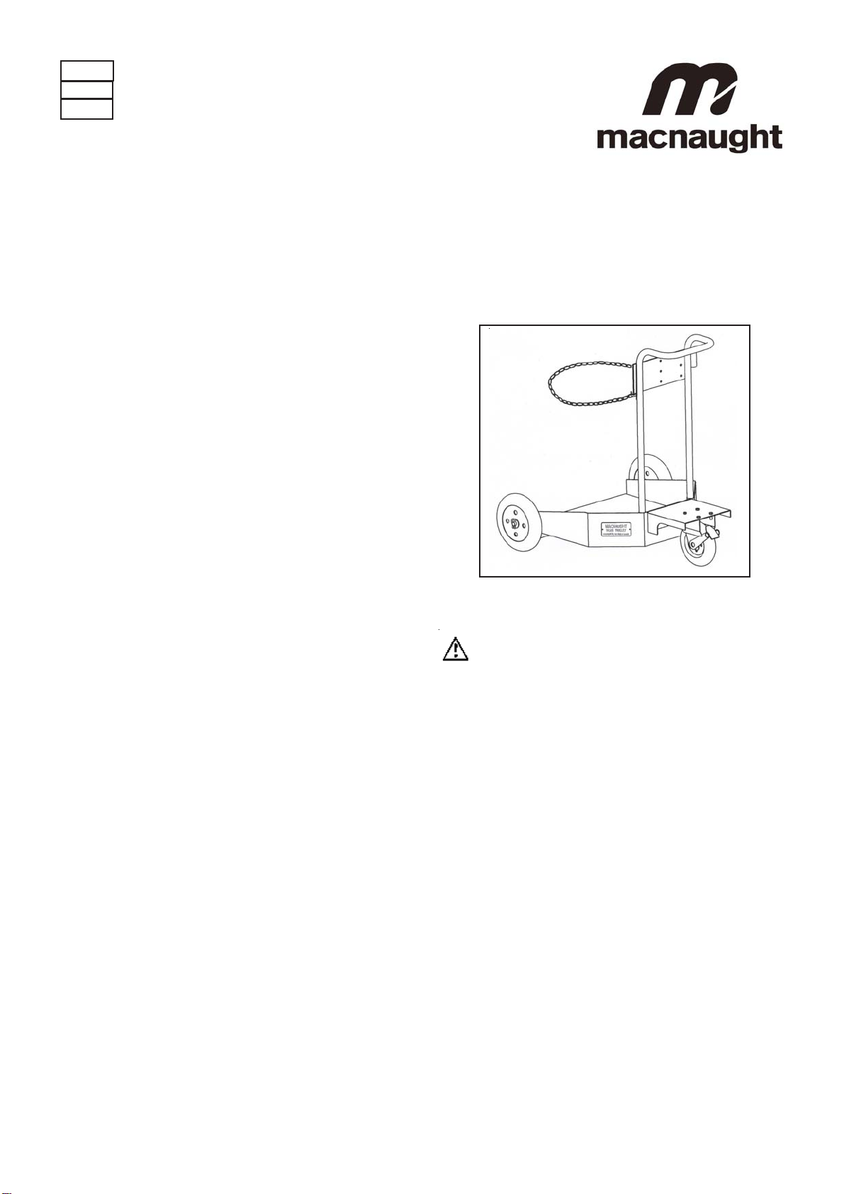
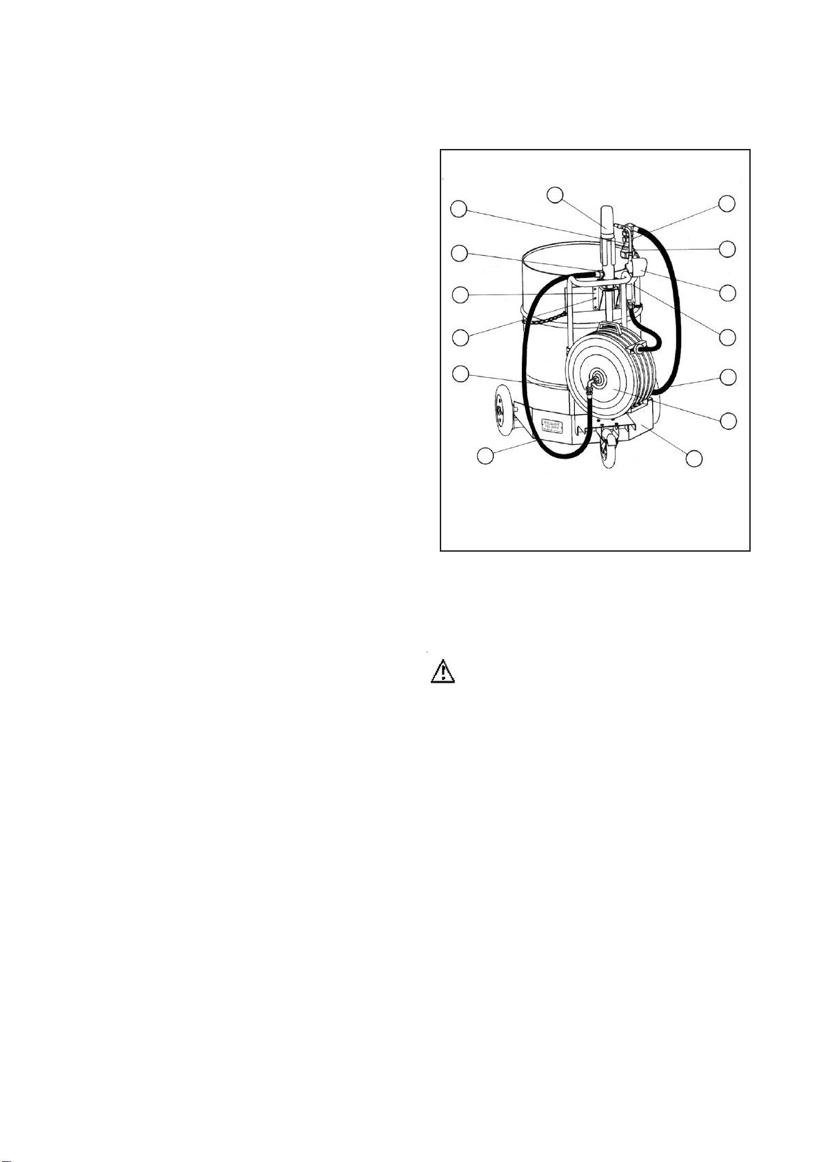
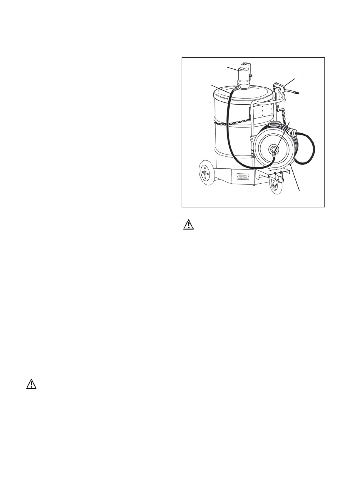
PARTS DIAGRAM
Macnaught Pty Ltd
POBox90ArncliffeNSW2205Australia
Telephone (02) 95670401
Facsimile (02) 9597 7773
Web:www.macnaught.com.au
macnaught warranty
1. Macnaught Pty Ltd (“Macnaught”) warrants that all products manufactured by Macnaught and/or supplied by
Macnaughtunderthe“Macnaught” brand,excluding M-Seriespositive displacementmeters (“Meters”)and components
subject to wear, will be free from any defects caused by faulty materials or workmanship (“Warranty”) for a period of
5 years from the date of purchase of the product.
2. For products (excluding Meters) which carry the “Macnaught design ”endorsement, an additional Warranty period
of5 yearsapplies toall mechanicalcomponents (excludingelectronic andelectrical components),giving atotalWarranty
period of 10 years.
3. For Meters, the Warranty period is 12 months from the date of purchase of the product.
4. For components contained in all products which are usually subject to wear from normal operation of the products
(such as o-rings, seals, springs, hoses and batteries), the Warranty period is 12 months from the date of purchase of
the relevant product.
5. For products and components which are not manufactured by Macnaught and are supplied by Macnaught under a
brand name other than “Macnaught”, the Warranty period is the longer of 12 months from the date of purchase of the
relevant product and the period of the manufacturer’s warranty.
6. The warranties contained in clauses 1, 2, 3, 4 and 5 above are conditional on the purchaser, during the relevant
Warranty period: a. delivering to Macnaught a detailed notice setting out full details of any defect in any product and
details of the date and place of purchase (together with copies of purchase receipts and/or
other supporting documents), and
b. at the purchaser’s own cost, returning the defective product to the nearest
authorised Macnaught service centre.
7. Subject to compliance by the purchaser with clause 6, Macnaught shall, at its option, repair or replace any product
or component found defective by its inspection by reason of faulty materials or workmanship of Macnaught.
8. This Warranty does not cover the failure of products, parts or components which, in the sole judgment of the
Macnaught,arises otherthan fromfaulty materialsor workmanshipof Macnaught,including misuse,abrasion, corrosion,
negligence,accident, substitutionof non-Macnaughtparts, unauthorisedmodification, improperuse, storageorhandling,
faulty installation or tampering by the purchaser or any third party.
9. If Macnaught’s inspection discloses no defect in material or workmanship, repair or replacement and return (at
Macnaught’s sole option) will be made at customary charges, which will be advised to the purchaser.
10. Macnaught’s liability and the purchaser’s rights under this Warranty shall be limited to the repair or replacement
of defective products or components and particular, shall not extend to any direct, special, indirect or consequential
damage or losses of any other warranties.
11. The foregoing Warranty supersedes, voids and is in lieu of any other warranties.
This Warranty does not form part of, nor does it constitute, a contract between Macnaught and the end-user or
purchaser. It is additional to any warranty given by the seller of the products. This Warranty does not exclude, limit,
restrictor modifythe non-excludablerights orremedies conferredupon theend-user orpurchaser, orthe non-excludable
duties or liabilities imposed on the seller or Macnaught, by Part V, Division 2, 2A, and Part VAof the TradeAct1974
(Commonwealth)or otherrights conferredon theend-user orpurchaser orduties orliabilities imposedupon Macnaught.
Item No off Part or set Kit. Ref Part name
1 1 TR100 Trolley Base
2 1 Trolley Handle
3 1 TR100s Safety Chain
4 1 Caster c/w Brake
5 4 TR106s A Nut
68 A Washer
74 A Bolt
8 2 Wheel
9 2 TR105s A Cotter Pin
10 4 A Washer
11 2 A Set Screw
Parts contained in Nut and bolt Kit TR205-1K "A"
Item No off Part or set Kit. Ref Part name
1 1 TR205 Trolley
2 1 * R300S Oil Pump (3:1)
3 1 * OLP100 Oil Reel
4 1 GM38s Suction Tube Assembly
51* OilGun
6 1 * Oil Gun Boot
7 1 GR34S Bung Adaptor Set
8 1 N51S Nut & Bolt Set
9 1 TD20 Wall Bracket
10 1 RH109 Suction Hose 3/4" x 1.5m (BSP)
11 1 RH108 Feeder Hose 1/2' x 1m (BSP)
12 1 N384 Reducing Bush
13 1 TD113 Adaptor
14 1 RB5S Support Washer / Collar Set
* Nominate Pump Model when ordering replacement parts
* Nominate Oil Reel Model when ordering replacement parts
* Nominate Oil Gun Model and Boot colour when ordering replacement parts
Item No off Part or set Kit. Ref Part name
1 1 TR205 Trolley
2 1 P8-11 P8-11 Grease Pump (complete)
3 1 GR100 Grease Reel
4 1 Support Washer
5 1 Support Coller