2
New for 2017 – v2 changes
There are a number of changes to the v.2 switching board. These changes were made to conform to my personal
preferences with effects building and what I perceive most DIY will appreciate. My only intention is to make the process of
building the VFE projects slightly easier and to require less workarounds for different styles of building.
- 1/4W resistors instead of 1/8W.
- Elimination of “sleeve make” style jack and necessary workarounds when using other types of jacks.
- Eliminated the PCB mounted DC Jack.
- Inclusion of the option to use no PCB mounted hardware.
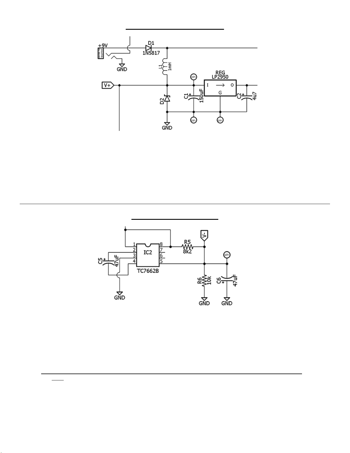
- Slight change in power decoupling with the micro-controller (low profile 4u7 electrolytic and 100n MLCC).
- PCB mounted jacks (optional) were moved slightly inward for easier mounting in the 1590B enclosure.
- Larger pads for easy soldering.
- Nearly the exact same size as the previous switching board.
By in large, there are no circuit changes except for the power decoupling on the micro-controller. And, this was only done
to serve my personal preference (yeah, completely selfish).
The Basics
The VFE Switching Board and micro-controller are included with all the VFE projects available from madbeanpedals.
This switching scheme employs “soft bypass”, meaning a momentary non-latching SPST foot-switch is used in place of
the ubiquitous 3PDT. This offers some advantages:
SPST momentary switches and relays generally have much lower failure rate than the 3PDT.
It’s easier to actuate than a latching bypass.
Nearly silent operation (no more mechanical “pops!”).
Secondary “momentary” function.
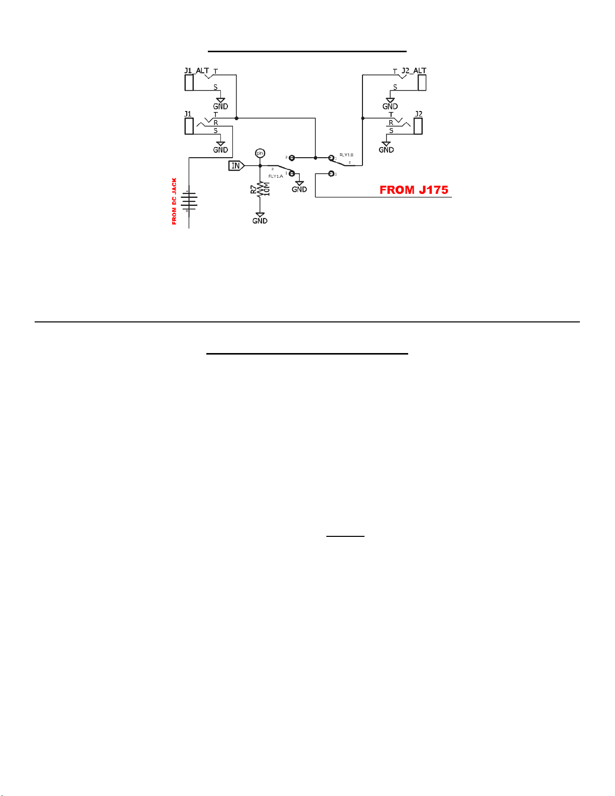
The switching scheme utilizes a pre-programmed micro-controller to actuate a DPDT relay. This relay handles I/O
functions for the (separate) audio effects boards. Therefore, the Switching Board must be wired to an audio board to
complete the bypass switching for the effects.
VFE has also gotten very clever; in addition to the components necessary to operate the switching, other circuitry is
included. These are power filtering for DC supply, an optional charge pump (since many of the VFE effects use a split-rail
power supply), effect input and output pull-down resistors as well as on-board DC and I/O jacks. This greatly simplifies the
design of the individual audio boards in each project since the common portions to all audio effects are handled by the
Switching Board.
The Switching Board is held in place with (optional) board mounted audio jacks. The momentary switch is attached via
two wires and is not directly mounted to the Switching Board. This means you will need precision when drilling your
enclosure to ensure the jacks fit properly and the DC Jack clears its drill hole. Fortunately, Peter has been kind enough to
make a demonstration video to show you how to build these projects to the VFE standard!
Notes:
The schematic lists TQ2-L-5v as the relay in this schematic, but VFE used the TQ2-L-4.5v as well. According to Peter
both work fine but he tended to use the 4.5v relay. The 5v is listed in the Mouser BOM because it is more regularly
stocked.
If using a battery, you must use board-mounted jacks to fit it all in. If using non-board mounted jacks you will probably not
be able to fit a battery.
How to finish a VFE Pedal build - Peter Rutter
https://www.youtube.com/watch?v=vAvK-yB_29M