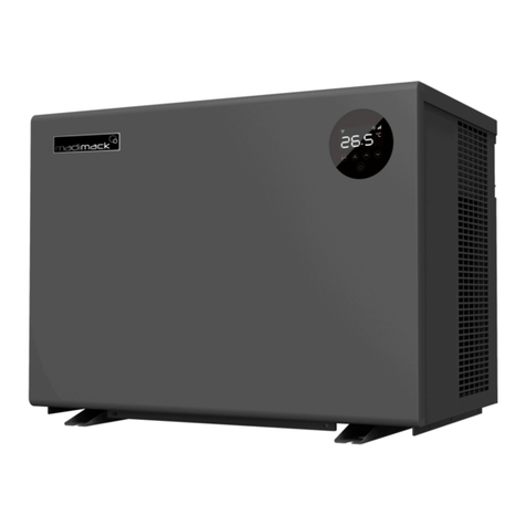
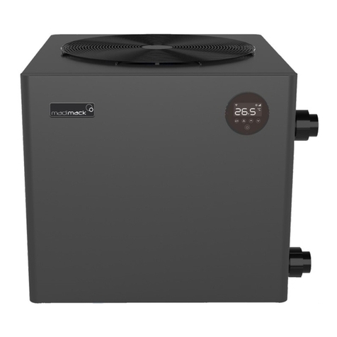
Madimack ELITE V3 User manual

1

INDEX

a. FOREWORD
Thank you for choosing the Madimack high efficiency inverter pool heat pump!
All our heat pumps are built and designed to the highest standard and are protected by our
extended warranty service for peace of mind.
Warranty registration is required to be submitted online in conjunction with the
commissioning page and warranty registration page in the Appendix section at the back of
the booklet www.madimack.com.au/warranty-registration.
Please read and fully understand all information provided before attempting to install the
pool heat pump.
For technical questions and further information please contact [email protected].
We hope you enjoy using our heat pumps.
Thank you!

COVER THE BASICS:
1. Check that you have received the package in good condition
2. Every residential heat pump comes with two accessory boxes and the manual. The manual will
mention all the parts and where they belong to make sure that the unit is commissioned, as per
the 'commissioning' section, and that adequate water flow rate is provided
3. Keep the surroundings of the unit clear of any debris, tree branches, and anything that can affect
the ventilation of the unit
4. Keep the invoice/packing slip in a safe place.
5. Register the unit for warranty as per the warranty section in this manual
6. Ensure that the unit is installed in an outdoor area, if it has to be indoors the unit will need to be
ducted to the outside
7. The condensate drain will need regular check-ups for any blockages or debris build ups,
Keeping it clean allows the condensate drain to escape easily to drainage
8. For Wi-Fi control make sure that you have full Wi-Fi strength in the heat pump area, more than
-50 DB is recommended for strong connection
9. Make sure that the unit is installed as per the ventilation diagrams to ensure efficient heating rates

2
Safety
Precautions
b.

3
We have provided important safety messages in this manual for the installation, maintenance and
repair of your heater.
Please read thoroughly and obey all safety messages.
Environmentally friendly R32 Refrigerant is used in this heat pump.
1. Warning
This WARNING sign denotes a hazard. It calls attention to a procedure,
practice, or the like, which, if not correctly performed or adhered to, could
result in personal injury or injury to a third party. These signs are rare, but
are extremely important.
a. Keep the heat pump away from fire source.
b. Unit must be placed in a well-ventilated area; indoor or enclosed areas
are not allowed.
c. Repair and disposal must be carried out by trained service personnel
d. Vacuum the system completely before welding. Welding should only
be carried out by professional trained personnel.

4
2. Attention
a. Please read the following instructions before installation, use and maintenance.
b. Installation, must be completed only by competent persons only, and in accordance with this
manual.
c. Check all water connections are sealed and tested before operating the machine
d. Except for the methods recommended by the manufacturer, do not use any methods to
accelerate the defrosting process or clean the frosted parts.
e. If a repair is required, please contact the nearest after-sales service center. The repair
process must be strictly in accordance with this manual. Repairs made by unauthorized
persons may void the warranty.
f. Correctly set temperature required for personal preference making sure to avoid overheating
or overcooling.
g. Please do use or stack substances or other materials which may block the air flows to the
inlet or outlet areas. This causes the efficiency of the heater to be reduced, and may damage
the machine.
h. Do not use or stock combustible gas or liquids such as thinners, paint and fuel, to avoid fire!
i. In order to optimize the heating effect, please install heat preservation insulation on pipes
between swimming pool and the heater, and please use a recommended cover on the
swimming pool.
j. Connecting pipes of the swimming pool and the heater should be less than 10m.
3. Safety
a. Please keep the main power supply switch out of reach from the children.
b. If power is suddenly disconnected during operation, and later the power is restored, the
heater will start up automatically.
c. Please switch off the main power supply in high storm weather to prevent the machine from
damage that could be caused by lightning strikes.
d. Any repairs should be carried out in a well-ventilated area. Any source of ignition is prohibited
during the inspection.
e. Safety inspection must be carried before the maintenance or repair for heat pumps with R32
gas in order to minimize the risk.
f. If R32 gas leaks during the installation process, all operations must be stopped immediately
and call your local service center.

5
About
your heat
pump
c.

6
1. Transportation
a. Always keep upright
b. Do not lift the water union
(Otherwise, the titanium heat exchanger may be damaged)
2. Accessories
Connection of the condensate drainage kit:
Water Union
Drainage kit
4 x Rubber Feet
Water Union
Drainage kit
Water Union
Drainage kit

7
3. Features
a. DC Twin-rotary inverter compressor of Mitsubishi
b. DC Brushless fan motor
c. EEV Technology
d. Reverse cycle defrosting with 4-way valve
e. High-efficiency twisted titanium heat exchanger
f. Sensitive and accurate temp control and water temp display
g. High pressure and low-pressure protection
h. Full protection on electrical system
4. Operating range
To prov i d e y o u c o m f o r t and pl e a s u r e , p l e a se set swi m m i n g p o o l w a t er temperature efficiently and
economically.
a. The heat pump can work between air -15°C~43°C,
b. Temperatu r e o f h e a t i ng 18℃~40℃
c. Temperatu r e o f c o o l i ng 12℃~30℃
Ideal operation range is between air 15°C ~ 25°C.

8
c
5. Introduction of different modes
a. The heat pump has three modes: Power, Perfect and Silence.
b. They have different strengths under different conditions.
Mode
Modes
Strength
Power mode
Heating capacity: 100% ~ 20% capacity
Fast heating
Perfect mode
Heating capacity: 80% ~ 20% capacity
Automatic adjustment according to ambient
and water temperature, intelligent
optimization.
High efficiency and energy saving
Silence mode
Heating capacity: 50% ~ 20% capacity
Operating at night.

9
6. Technical parameter
Remarks:
This heat pump is able to perform normal within air temp -15°C
~
+43°C, efficiency will not be
guaranteed out of this range. Please take into consideration that the pool heat pump performance
and parameters are different under various conditions.
Related parameters are subject to adjustment periodically for technical improvement without
further notice. For details, please refer to nameplate.

10
7. Dimension
※ Above data is subject to modification without notice.
Note: Above swimming pool heat pump specification drawing is for installation reference only to
technical staff.
A
B
C
D
E
F
G
H
ESV3-110
510
450
504
530
749
300
75
656
ESV3-140
510
450
504
530
749
280
75
656
ESV3-170
510
540
504
530
839
350
75
656
ESV3-220
510
680
504
530
979
460
75
756
ESV3-270
520
760
514
540
1132
460
75
756
ESV3-320
ESV3-400
Name
Size(mm)
Model

11
Installation
Guidance
d.

12
1st case: Single unit – 2 obstacles:
Please note that these are absolute minimum distances and where possible should always
have a greater difference. Under no circumstances should any of the distances be reduced
as performance will be affected. More ventilation is better.
Model
number
ESV3-
110
ESV3-140
ESV3-170
ESV3-220
ESV3-270
ESV3-320
ESV3-400
Distance A
(mm)
300
350
400
500
500
500
500
Distance B
(mm)
300
300
350
400
400
400
500
Distance C
(mm)
100
150
200
250
300
300
300

13
2nd case: Multiple units – 2 obstacles:
Model
number
ESV3-110
ESV3-140
ESV3-170
ESV3-220
ESV3-270
ESV3-320
ESV3-400
Distance A
(mm)
300
350
400
500
500
500
500
Distance B
(mm)
300
300
350
400
400
400
500
Distance C
(mm)
100
150
200
250
300
300
300
Distance D
(mm)
600
700
800
1000
1000
1000
1000
Please note that these are absolute minimum distances and where possible should always
have a greater difference. Under no circumstances should any of the distances be reduced
as performance will be affected. More ventilation is better.

14
3rd case: Single unit – 3 obstacles
Model
number
ESV3-
110
ESV3-140
ESV3-170
ESV3-220
ESV3-270
ESV3-320
ESV3-400
Distance A
(mm)
400
450
500
600
600
600
600
Distance B
(mm)
400
400
450
500
500
500
600
Distance C
(mm)
300
300
400
450
500
500
500
Please note that these are absolute minimum distances and where possible should always
have a greater difference. Under no circumstances should any of the distances be reduced
as performance will be affected. More ventilation is better.

15
4th case: Multiple units – 3 obstacles
Please note that these are absolute minimum distances and where possible should always
have a greater difference. Under no circumstances should any of the distances be reduced
as performance will be affected. More ventilation is better.
Model
number
ESV3-110
ESV3-140
ESV3-170
ESV3-220
ESV3-270
ESV3-320
ESV3-400
Distance A
(mm)
300
350
400
500
500
500
500
Distance B
(mm)
300
300
350
400
400
400
500
Distance C
(mm)
300
300
400
500
600
600
600
Distance D
(mm)
700
800
900
1000
1000
1000
1000
A
B
C

16
Plumbing Multiple units:
Multiple heat pumps acting as one system should be connected in Cascade (Parallel Connection).
Adequate flowrate should be provided to all the units in the system to ensure efficient heating
(Please refer to the commissioning section in the manual to learn about heat pumps
commissioning). The diagram below represents the cascade connection

17
1. Installation reminder
Only competent persons are authorized to install the heat pump and should be educated with the
relevant building codes and standards of their current state or local governing body for all
electrical, mechanical and water services to prevent danger or damage to the unit.
a. Location and clearances
The inverter pool heat pump should be installed in a good ventilation place.;
b. Typical installation diagram
Installations can differ dependent on-site conditions below is only a representation of one
possibility.
Note: the inlet and outlet positions for the pipework is a representation only and can be positioned
differently.
Please see section: Installation options for more information of accessories available and
different plumbing layouts
water outlet
valve
water
return
Chlorinator cell
(or other treatment)
water inlet
valve
By-pass
valve
Filtration
pump
Filter
Pool
Table of contents
Other Madimack Heat Pump manuals
Popular Heat Pump manuals by other brands

Zodiac
Zodiac Z400 iQ Spare Parts/Accessories Instructions Manual

Pentair
Pentair ULTRATEMP 70 Installation and user guide

joule
joule Cyclone Installation & maintenance manual

Nibe
Nibe SOLAR 40 Installer manual

Black & Decker
Black & Decker BDXBT53 instruction manual

Bard
Bard W18HA-A installation instructions

Bard
Bard W18H2 installation instructions

Bryant
Bryant Preferred 225B Product data

Midea
Midea MCCU-14CN1 Technical manual

York
York YMB018 THRU 060 Technical guide

Ingersoll-Rand
Ingersoll-Rand A4AC4018A1000A Installer's guide

Crystal Enterprises
Crystal Enterprises BP-50HS-A Directions for installation and maintenance