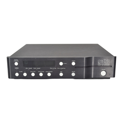
Madrigal Audio Mark Levinson 36 User manual

Madrigal Audio Laboratories, Inc.
Operating Manual
Mark Levinson®
Nº36
Digital Audio
Processor

CAUTION
RISK OF ELECTRIC SHOCK
DO NOT OPEN
CAUTION: TO REDUCE THE RISK OF ELECTRICAL SHOCK, DO
NOT REMOVE COVER. NO USER-SERVICEABLE PARTS INSIDE.
REFER SERVICING TO QUALIFIED PERSONNEL.
WARNING: TO REDUCE THE RISK OF FIRE OR ELECTRIC SHOCK, DO
NOT EXPOSE THIS APPLIANCE TO RAIN OR MOISTURE.
NOTICE
This equipment has been tested and found to comply with the limits for a Class B digital device, pursuant to Part 15 of the
FCC Rules. These limits are designed to provide reasonable protection against harmful interference in a residential
installation. This equipment generates, uses and can radiate radio frequency energy and, if not installed and used in
accordance with the instructions, may cause harmful interference to radio communications. However, there is no guarantee
that interference will not occur in a particular installation. If this equipment does cause interference to radio or television
reception, which can be determined by turning the equipment on and off, the user is encouraged to try to correct the
interference by one or more of the following measures:
• Reorient or relocate the receiving antenna;
• Increase the separation between the equipment and the receiver;
• Connect the equipment into an outlet on a circuit different from that to which the receiver is connected;
• Consult the dealer or an experienced radio/TV technician for help.
CAUTION: Changes or modifications to this equipment not expressly approved by the manufacturer could void the user’s
authority to operate the equipment.
HDCD®and High Definition Compatible Digital®are registered trademarks of Pacific Microsonics, Inc.
The information contained in the manual is subject to change without notice. The most current version of this manual will
be posted on our web site at http://www.madrigal.com.
The lightning flash with arrowhead symbol, within an equilateral triangle, is intended
to alert the user to the presence of uninsulated “dangerous voltage” within the
product’s enclosure that may be of sufficient magnitude to constitute a risk of electric
shock to persons.
The exclamation point within an equilateral triangle is intended to alert the user to the
presence of important operating and maintenance (servicing) instructions in the literature
accompanying the appliance.
Marking by the “CE” symbol (shown left) indicates compliance of this device with the EMC
(Electromagnetic Compatibility) and LVD (Low Voltage Directive) standards of the
European Community.

Important Safety Instructions
Please read all instructions and precautions carefully and completely before operating your Mark Levinson com-
ponent.
1. ALWAYS disconnect your entire system from the AC mains before connecting or disconnecting
any cables, or when cleaning any component.
2. This product is equipped with a three-conductor AC mains power cord which includes an
earth ground connection. To prevent shock hazard, all three connections must ALWAYS be
used. If your electrical outlets will not accept this type of plug, an adapter may be purchased.
If an adapter is necessary, be sure it is an approved type and is used properly, supplying an
earth ground. If you are not sure of the integrity of your home electrical system, contact a li-
censed electrician for assistance.
3. AC extension cords are not recommended for use with this product. If an extension cord must
be used, be sure it is an approved type and has sufficient current-carrying capacity to power
this product.
4. NEVER use flammable or combustible chemicals for cleaning audio components.
5. NEVER operate this product with any covers removed.
6. NEVER wet the inside of this product with any liquid.
7. NEVER pour or spill liquids directly onto this unit.
8. NEVER block air flow through ventilation slots or heatsinks.
9. NEVER bypass any fuse.
10. NEVER replace any fuse with a value or type other than those specified.
11. NEVER attempt to repair this product. If a problem occurs, contact your Mark Levinson®re-
tailer.
12. NEVER expose this product to extremely high or low temperatures.
13. NEVER operate this product in an explosive atmosphere.
14. ALWAYS keep electrical equipment out of the reach of children.
15. ALWAYS unplug sensitive electronic equipment during lightning storms.

4
From all of us at Madrigal Audio Laboratories, thank you for choosing the
Mark Levinson Nº36 Digital Audio Processor.
A great deal of effort went into the design and construction of this precision
device. Used properly, it will give you many years of enjoyment.

5
Table of Contents
Unpacking and Placement ........................................................................ 6
Send in Your Warranty Card! .............................................................................. 6
Unpacking the Nº36 ........................................................................................... 6
Placement of the Nº36 ...................................................................................... 6
Operating Voltage ...................................................................................... 7
A Quick Start… ............................................................................................ 8
Warm up/break-in period ................................................................................. 9
Special Design Features ............................................................................10
An “intelligent” FIFO .......................................................................................... 10
Superior isolation between sources ................................................................. 11
Fully balanced design ...................................................................................... 11
24 bit digital architecture and HDCD® compatibility ..................................... 11
HDCD® Gain-Matching ............................................................................. 12
Front panel, Nº36 ........................................................................................13
Display, Nº36 ............................................................................................... 17
Rear panel, Nº36 ........................................................................................19
IR input tip polarity .................................................................................... 20
Linking connections ................................................................................... 21
Building link cables ..................................................................................... 21
Male XLR output connector (digital) ....................................................... 22
AC power cord polarity ............................................................................ 22
Setup and Installation ............................................................................... 23
Nº36 Input Names ............................................................................................ 23
Making Digital Connections ............................................................................ 23
Making Analog Connections .......................................................................... 24
Making Link Connections ................................................................................ 25
Input Names ..................................................................................................... 25
Naming Your Inputs .......................................................................................... 26
Remote Control of the Nº36 ...................................................................... 28
Te a c hi n g N º36 Front Panel Commands .......................................................... 28
Teaching Other Nº36 Commands .................................................................. 29
special commands table ......................................................................... 29
Linked functions.......................................................................................... 31
Standby link ........................................................................................................ 31
Name link .......................................................................................................... 31
Play link .............................................................................................................. 31
Display Link ........................................................................................................ 31
Polarity link ......................................................................................................... 31
HDCD Link ......................................................................................................... 32
Troubleshooting ......................................................................................... 33
Care and maintenance ............................................................................ 34
U.S. and Canadian Warranty .................................................................... 35
90-Day Limited Warranty .................................................................................. 35
Five Year Extended Warranty ........................................................................... 35
Obtaining Service ..................................................................................... 36
Specifications ............................................................................................ 37
Dimensions ................................................................................................ 38

6
Unpacking and Placement
Send in Your Warranty Card! So far, you have only half a product. The other half is the ongoing service and
support we can provide you to complement your new component and help you
maximize your enjoyment of it. Unfortunately, we cannot give you this other half
of the product you just purchased unless you tell us where to find you
Sending in your warranty card will automatically add your name to our mailing
list for our customer newsletter, and will allow us to contact you for the occa-
sional special offer. We do not share this lait with anyone; all names are held in
strict confidence. We simply want the opportunity to provide superior service, as
our way of thanking you for buying one of our products.
Unpacking the Nº36 Unpack your Nº36 Digital Audio Processor and remove all accessories from the
carton. Keep all packing materials for future transport.
Included with your new Mark Levinson processor is a pair of knit, white gloves
designed to assist you in the initial unpacking and placement of your new pur-
chase. Please accept them as a token of our appreciation for having purchased
one of our products.
Placement of the Nº36 The Nº36 should be placed close to your digital source equipment, keeping inter-
connect cabling short. We strongly recommend shelf mounting to allow for
proper ventilation. The Nº36 is designed for continuous operation, which is why
it features a standby mode rather than a full “off” mode—it is designed to be
connected to the AC mains at all times for the best performance.
Be sure to allow 3 to 4 inches of clearance above the Nº36 to allow heat dissipa-
tion through air circulation.
Drawings are included in this manual to facilitate special installations and custom
cabinetry (see “Dimensions”).

7
Operating Voltage
The Nº36 Digital Audio Processor is set at the factory (internally) for 100V, 120V,
200V, 230V, 220V, or 240V AC mains operation @ 50 or 60Hz. (230V/50Hz only in
European Union countries, in compliance with CE regulations.) This voltage set-
ting cannot be changed by the user. Make sure that the label on the bottom panel
of the Nº36 (adjacent to the AC cord) indicates the correct AC operating voltage
for your location.
If the voltage indicated on your Nº36 is incorrect, or if you wish to change the
AC operating voltage of your Nº36 as the result of moving to a different country
than the one in which you purchased your digital audio processor, see your Mark
Levinson dealer.
The Nº36 can be powered by a normal 15-ampere AC mains line. If other devices
are also powered from the same AC line, their additional power consumption
should be taken into account.
For optimal sonic performance and longevity, the Nº36 is designed to remain
powered at all times (the standby switch merely mutes the processor’s outputs
and turns off the display). There is an initial break-in period of approximately
300 hours before the Nº36 achieves optimum performance.

8
A Quick Start…
We recognize that many people are understandably eager to begin listening to
their new components, and that reading the manual is often done (if at all) at a
later time—perhaps while listening to music through the new product itself. We
strongly recommend that you read this manual thoroughly, as the Nº36 Digital
Audio Processor incorporates several unusual features which enhance its opera-
tion.
Fortunately, we can help you get some music up and running on your system
quickly, so that you may begin enjoying your new digital processor while reading
more about it. The goal here is simply to make some music as quickly as pos-
sible. The following procedure assumes that the rest of your system is already
connected (e.g., preamplifier to power amplifier, to speakers, etc.).
1 TURN OFF YOUR ASSOCIATED COMPONENTS
This minimizes the opportunity for a momentary electrical surge disturbing
your system while making connections. If you have a large power amplifier,
allow its power supply to fully discharge before proceeding (which may
take as long as several minutes, depending on its design).
2 CONNECT THE AC CORD TO THE Nº36 AND TO YOUR AC OUTLET
The AC receptacle for the power cord is located underneath the Nº36, in
the center of the unit. (This design reduces noise by bringing the power
into the chassis precisely where it is needed rather than routing it through-
out the unit.) The Nº36 will take a few moments to initialize and will then
be ready to use.
3 CONNECT A DIGITAL SOURCE TO INPUT 1 OR 5
Inputs 1 and 5 on the Nº36 are configured from the factory for CD trans-
ports, the most common type of digital transport. Input 1 is an aes/ebu
(XLR-type) digital input; Input 5 is an S/PDIF (RCA-type) digital input.
These digital inputs are found on the rear of the Nº36. Use high quality
digital cable such as Madrigal MDC-1 for XLR-type, or MDC-2 for RCA-type
connections. (All other inputs are configured as “not used” and will need to
be named before they can be used. Naming of inputs is covered in this
manual.)
4 CONNECT A SET OF ANALOG OUTPUTS TO YOUR PREAMPLIFIER
The Nº36 has both balanced (XLR) analog outputs and single-ended (RCA)
outputs. They are found on the outside edges of the rear panel. As viewed
from the front, the left side contains the Left channel and the right side
contains the Right channel. Use high quality analog cable such as Madrigal
HPC.

9
5 SELECT THE INPUT YOU ARE USING BY PRESSING ITS FRONT PANEL BUT-
TON
6 TURN ON THE OTHER COMPONENTS; SLOWLY RAISE THE VOLUME
Congratulations! You should now be able to enjoy your favorite music while
reading the rest of this manual. [Note that it is always a good idea to turn
on your power amplifier(s) last, in case one of your other components ex-
hibits a turn-on transient of some sort.]
Warm up/break-in period Although your Mark Levinson Nº36 digital processor delivers outstanding perfor-
mance straight out of the box, you should expect to hear it continue to improve
as it reaches its normal operating temperatures and its various components
“break-in.” It has been our experience that the greatest changes occur within the
first 25-50 hours, but that the Nº36 will continue to improve in sound quality for
about 300 hours, after which time it remains quite constant.
The only exception to this rule is if power is removed from the unit, allowing it
to cool down. In this case you should expect a brief warm-up period before the
Nº36’s sound quality is at its best. (Fortunately, you will never have to repeat the
full 300 hour break-in period.)

10
Special Design Features
Congratulations on your purchase of the Nº36 Digital Audio Processor. The Madri-
gal design team is confident you will enjoy the outstanding performance of the
Nº36 for many years. In case you are interested in technical details, what follows
is a brief outline of some of the key technologies in your new processor.
An “intelligent” FIFO Unlike previous processors which were highly dependent on the quality of the
digital signal they were fed, the Nº36 Digital Audio Processor delivers outstanding
performance with even less-than-ideal digital signals.
“FIFO” stands for “First In, First Out.” It describes a simple buffer in which the
digital information is stored temporarily on its way to being converted to analog.
Just as a large water tower can provide a steady source of water to a small town,
despite hour-to-hour variations in the supply of water from the well, a FIFO can
provide a steady, consistent source of digital data to the converters which are re-
sponsible for changing that data into music. Even if there is significant “jitter” (in-
consistencies in timing) in the incoming digital information, the output of the
FIFO is controlled by a special clock with tremendous accuracy. The result largely
eliminates the jitter and allows the musical information to be reproduced cleanly,
without jitter-induced distortions.
The trouble with most FIFOs lies in their behavior when the incoming signal is
poor enough to cause the “water tank” to overflow or to be emptied. Normally, a
FIFO would then have to “invent” false data to fill the gap, throw away excess
data, or revert to non-FIFO operation. None of these approaches is acceptable, as
they all represent serious performance compromises.
Of course, one could simply use an extremely large buffer. Unfortunately, this so-
lution is a poor one.
A larger buffer implies a longer delay between when information goes in and
when it starts coming back out. With laserdiscs, for example, you must keep the
in/out delay small so as to keep the soundtrack synchronized with the picture on
the screen. An oversized buffer would make every movie’s audio out of step with
its video, an unacceptable situation. Of course, one could bypass the FIFO for
movies, at the cost of losing all of its distortion-reducing benefits.
Madrigal engineers have developed a proprietary buffer management scheme
which reduces reproduced jitter to less than 20 picoseconds while maintaining
the synchronization of sound and picture in movies. It employs a buffer large
enough to absorb the jitter found in transports of reasonable quality, yet small
enough to have imperceptible delay. The rate at which data is released from the
FIFO buffer is controlled by software to track the long-term data rate of the in-
coming signal, allowing the buffer to absorb all the short-term variations which
cause sonic degradation. This approach yields a “smart” FIFO buffering scheme
which rejects virtually all incoming jitter without requiring an enormous buffer
and suffering the consequent audible delay. It also avoids the sonic penalties asso-
ciated with the various strategies used when a buffer overflows or empties.
The “smart” FIFO operates at both 44.1 kHz and 48 kHz sampling rates. The Nº36
reverts to non-FIFO (recovered clock) operation for 32 kHz sampling rates (a
proposed but rarely used standard for digital satellite transmission). It also reverts

11
to the recovered clock when the long-term data rate from the transport is ex-
tremely inaccurate. (Sorry—the digital output of your CD portable will not sound
as good as a fine CD transport such as the Mark Levinson Nº31.)
Superior isolation
between sources
One of the advantages of a separate digital audio processor is that you can take
the money which might have otherwise been spent on several built-in D/A con-
verters and put it into one, superior processor which will enhance the perfor-
mance of all the transports with which it is used. Ironically, many outboard pro-
cessors fail to live up to this potential due to interference between their various
digital inputs.
The Nº36 provides outstanding isolation between its inputs, realizing the full po-
tential of the various digital transports with which it is used. In fact, all
unselected digital inputs are capacitively shunted to ground upon entering the
Nº36 to prevent their interaction with any portion of the circuitry inside the pro-
cessor. As a result, the selected input effectively has the Nº36 “all to itself” for its
conversion to analog.
Fully balanced design The Nº36 is fully balanced in both the analog and digital domains. Even single-
ended digital inputs (anything other than the balanced aes/ebu standard) are im-
mediately converted to balanced signals before any further routing or processing
of the signal. All digital filtering and processing is implemented in a balanced
configuration, and conversion to analog is accomplished in two opposing polarity
20-bit converters per channel.
This approach maintains the integrity of the signal, reducing the opportunities for
music-destroying noise and digital artifacts to enter the signal path.
24 bit digital architecture
and HDCD®compatibility
All digital filtering and processing maintains a true 24-bit throughput capability,
providing greater digital resolution than any existing source component. Even the
most stringent requirements of professionals can easily be met with this design.
In addition to true 20-bit capability (24 bits in the digital domain, filtered to the
20-bit resolution of the digital to analog conversion stages), the Nº36 also incor-
porates High Definition Compatible Digital®decoding to take full advantage of
the increased resolution available from HDCD encoded 16-bit CDs. The High
Definition Compatible Digital®format retains much of the resolution inherent in
professional twenty bit recordings by encoding this information more efficiently
within the sixteen bit space available within the Compact Disc format.
The technology embodied in the Nº36 sets it apart from other high end products,
one which will stand the test of time.

12
HDCD®Gain-Matching
Some HDCD-encoded recordings are mastered at a level which is noticeably lower
(6 dB) than conventional recordings. To avoid unexpected changes in volume when
going from one disc to another, the Nº36 automatically reduces the volume of all
recordings to this volume level as required by Pacific Microsonics, Inc. Thus, this
“HDCD AUTO” gain-matching is the default setting as shipped. To remind you of
this fact, the Nº36 will display “-6 DB PAD” when locking on a digital input signal,
unless this feature is defeated as indicated below.
In our listening tests, we have determined that the only sonically transparent gain-
matching technique is to raise the volume of the preamplifier by the requisite 6 dB
when playing those few discs that require it. All other design options introduce
a compromise in sound quality.
For Best Performance: We strongly recommend that you turn off the HDCD AUTO gain-
matching in your Nº36 digital audio processor.
If you are using the Nº36 with a Mark Levinson Nº38 or Nº38S preampli-
fier, simply name the appropriate input on the preamplifier “No36” (explained in
the preamp manual), and connect the two products with a Communications Link
cable (page 21). In this case, the Nº36 will tell the preamplifier to change its volume
setting as necessary to compensate for differing CD mastering techniques, and you
never have to think about it. (The Nº38 display will show “HD+6” to indicate a
change required by the HDCD recording being played through the Nº36; it will revert
to normal and show “HD+0” when you return to conventional recordings. Older
preamplifiers may require a new EPROM to take advantage of this feature.) This
technique ensures that you always get the best possible sound from your system,
without any unexpected changes in level, regardless of the recordings you play.
If you are using the Nº36 with any other preamplifier, follow the steps below.
(You will have to adjust the volume on some HDCD recordings manually.)
1 PRESS AND HOLD THE MODE BUTTON ON THE FRONT PANEL
After a few seconds, the display will change to show NAME and the current
name of the selected input. (Ignore this for now. You’ll learn how to rename
your inputs to match your sources later on in this manual.)
2 PRESS THE POLARITY BUTTON SO THE DISPLAY SHOWS “HDCD MAN.”
Repeatedly pressing the polarity button will toggle the display between “HDCD
AUTO” (meaning that the Nº36 automatically lowers its volume on convention-
ally-mastered discs) and “HDCD MAN.” (meaning that gain-matching is turned
off; HDCD-encoded discs will still be decoded properly). If you try to change
from one to the other while a Nº38 is Linked, the Nº36 will display “No38
LINK” (indicating that the Nº36 and Nº38 already know what to do).
Changing to manual gain-matching ensures that the HDCD digital filter always
operates at its maximum resolution, although you may now have to manually
turn up the volume on some HDCD recordings.

13
polarity
invert
MADRIGALAUDIO LABORATORIES
R
display
intensity
aes/ebu emphasis
123456 standby
DIGITAL PROCESSOR
Nº 36
mode
teach ir
876
31 2
9
54
Front panel, Nº36
1 DISPLAY INTENSITY
Pressing this button varies the brightness of the display. Four brightness lev-
els are available.
When power is first applied to the Nº36 (or when power is restored after
an interruption), the display is automatically set to its brightest level.
Pressing the display intensity button once dims the display one level;
pressing it again dims it further; pressing it again turns the display off.
Pressing display intensity once more returns the display to its brightest
level. (If other Mark Levinson components in the system are “Linked” to the
Nº36, all display intensities will change in unison. See Linked Functions for
more information.)
2 AES/EBU LED
The aes/ebu LED lights when the Nº36 detects that the digital program be-
ing processed conforms to the AES/EBU (Audio Engineering Society/Euro-
pean Broadcast Union) professional standard. This LED indicates the pres-
ence or absence of certain encoded information in the digital signal. It does
not indicate that the AES/EBU connections (a connection standard written
by the same group) are being used. Playback of non-AES/EBU CDs or DATs
won’t activate the aes/ebu LED, even if the associated transport is con-
nected according to the AES/EBU standard.
3 DISPLAY
See “Display, Nº36” beginning on page 16.

14
4 MODE BUTTON
The mode button serves two functions, one in day-to-day operation and
the other only during setup:
• In everyday use, the mode button allows you to see the status of the
digital output and to turn it on or off.
• During setup, the mode button allows you to rename the various inputs
of the Nº36 to suit the needs of your system, making it easier to use (es-
pecially for those who use the system infrequently).
To check on whether your selected input is present at the digital output,
press mode once. This action causes the display to indicate whether the
digital record output is on or off. For example, the display shown below in-
dicates that the digital record output is on.
To disable the digital record output, press the mode button again. The dis-
play will read RCD: OFF and the digital output of the Nº36 will be tempo-
rarily disabled. This eliminates any potential interaction between the record
output circuitry of the Nº36 and the rest of your system. Repeatedly press-
ing the mode button while RCD: shows in the left half of the display will
toggle the Nº36 between RCD: OFF and RCD: ON for the selected source.
After a few seconds, the display will return to its normal mode, which is to
display the selected source and current sampling frequency.
5 EMPHASIS LED
The compact disc standard, as created by Sony and Philips, allows a high-
frequency boost to be employed during recording. This boost, called re-
cording pre-emphasis, increases the signal-to-noise ratio at high frequencies,
but must be countered by a high-frequency cut before playback to restore a
recording’s normal frequency response. De-emphasis may be done as the
recording is being mastered, or the compact disc (or digital audio tape)
may be made with the pre-emphasis still on, and the de-emphasis per-
formed in the playback unit.
The emphasis LED lights when the Nº36 detects recording pre-emphasis in
the digital program being processed, and subsequently employs its de-em-
phasis circuitry. In the Nº36, the de-emphasis filtering is done in the digital
domain.

15
Note: The de-emphasis circuitry of the Nº36 is designed to be
compatible with all known digital standards. However, it is
possible for the emphasis LED to light in error when there is
no disc being played. This is not a malfunction of the Nº36.
Rather, it is the result of the transport generating ambiguous
signals in the absence of a spinning disc to read. You may
never see this condition. Even when the condition exists, it
has no effect on sonic quality, as it can only occur when
there is no disc playing.
6 POLARITY INVERT
Pressing this button inverts the polarity of the digital signal, to compensate
for polarity differences during the recording process. Some recordings may
simply “sound better” when this function is active.
While polarity invert is selected, the LED above the button will light.
Note:polarity invert doesn’t affect the digital outputs, and isn’t available
for inverting the polarity of digital signals to be recorded.
Note:polarity invert may be operated by infrared remote control
when the Nº36 is connected to compatible Mark Levinson com-
ponents such as the Nº31 Reference CD Transport. Complete
instructions are included in those components’ operating manu-
als. Alternatively, the Nº36 can “teach” a learning remote control
infrared control codes that will provide similar functionality. (See
“Remote Control of the Nº36”)
7 SOURCE SELECTION BUTTONS
Pressing any of these buttons selects the digital source associated with that
numbered input, according to the connections on the rear panel (see “Rear
panel, Nº36”). The display will show the name of the input, along with the
input number. (See “Setup and Installation” for more information on nam-
ing your inputs to match your sources.) Only one source at a time may be
selected.
When power is first applied to the Nº36 (or when power is restored after
an interruption), it will search for and select the first input with an active
digital signal. If none is found, it will select the first named source. As deliv-
ered from the factory, this input will be “CD1.”
When the Nº36 is taken out of standby mode, the source last selected be-
fore pressing standby will be automatically selected.
8TEACHIR
The Nº36 has both an infrared receiver and an infrared transmitter in its
main display, enabling it to respond to IR remote controls that have
“learned” the appropriate commands. The Nº36 can “teach” these commands
to a learning remote control.
For more information on using the teach ir function of the Nº36, see “Re-
mote Control of the Nº36”

16
9 STANDBY & STANDBY LED
Pressing this button takes the Nº36 out of “standby” mode (provided the
Nº36 is connected to AC power), making it fully operational.
Pressing standby again places the Nº36 into standby mode, which turns the
display off, turns off all outputs (including the record outputs), and disables
the front-panel controls. The internal circuitry remains powered up in order
to maintain its thermal stability and optimum performance at all times.
While the Nº36 is in standby, the LED above the standby button flashes ap-
proximately every five seconds. (When the Nº36 is Linked to other Mark
Levinson components, all the standby lights will blink in unison.) When the
Nº36 is ready to operate (that is, when it is not in standby mode), this LED
remains lit continuously.

17
1 2 3
Display, Nº36
1INPUTNAME
This part of the Nº36’s display shows the name of the input selected, as
determined during setup (see “Assigning input names” in the “Installation”
section of this manual).
To facilitate operation in complex, multisource systems, the Nº36 is capable
of displaying a wide variety of names for each of its eight inputs. They are
listed below.
NOT USED (any unused input)
DAT Digital Audio Tape
DCC Digital Compact Cassette
MD Mini Disc
CDR Compact Disc, Recordable
CDI Compact Disc, Interactive
DBS Digital Broadcast Satellite
LD Laser Disc
CD Compact Disc
ADC Analog to Digital Converter
AUX Auxiliary (other digital sources)
DCA Digital Cable Audio
PCD Proceed Compact Disc player
PDT Proceed Digital Transport
CDD Compact Disc Drive
2INPUTNUMBER
This part of the Nº36’s display shows the input number of the selected digi-
tal source, according to the connections on the rear panel (see “Rear panel,
Nº36”).

18
3 SAMPLING FREQUENCY
This part of the Nº36’s display normally shows the sampling frequency of
the digital input being processed, expressed in kilohertz. One of three sam-
pling frequencies will be shown, in “shorthand” form: 32k, 44k, or 48k, (44k
is shown in the main illustration on the opposite page).
After you press one of the source selection buttons (say, going from input 1
to input 5), the Nº36 will reduce the volume and the display will show:
While the Nº36 is attempting to lock onto a different digital signal, the dis-
play will show (assuming you have renamed input 5 for your DAT):
If no digital signal is present (if the source is turned off, is improperly con-
nected, or is disconnected), the display will show:

19
and High Definition Compatible Digital®are registered trademarks of Pacific Microsonics, Inc.
left analog outputs
PUSH PUSH
right analog outputs 1
aes/ebu 2
aes/ebu
external
i.r.
master
communication
port
DIGITAL PROCESSOR Nº36
designed and manufactured in U.S.A.
by
MADRIGAL S/N
21 3
6
eiaj
5
spdif
4
spdif
3
st
digital output
4 5 678910 12
Rear panel, Nº36
1 BALANCED ANALOG OUTPUTS
These outputs provide balanced line-level analog audio (via cables
equipped with XLR-type connectors) to a preamplifier, integrated amplifier,
or receiver equipped with balanced inputs (see “Set-up and installation”).
The pin assignments used are AES-standard, as shown below:
12
3
Pin 1: Signal ground
Pin 2: Signal +(non-inverting)
Pin 3: Signal –(inverting)
Connector ground lug: chassis ground
2 SINGLE-ENDED ANALOG OUTPUTS
These outputs provide single-ended line-level analog audio (via cables
equipped with RCA-type connectors) to a preamplifier, integrated amplifier,
or receiver.
3 AES/EBU ELECTRICAL DIGITAL INPUTS (#1 & #2)
These inputs accept the digital audio signal (DAS) via cables equipped
with XLR-type connectors from digital sources such as a compact disc
transport, laser disc transport, digital audio tape transport, digital broadcast
receiver.
These inputs conform to the AES/EBU digital interconnection standard,
which calls for a 110Ωtransmission of the DAS. Use a digital interconnecting
cable specifically designed for the 110ΩAES/EBU standard, such as Madrigal
MDC-1 cable, when using these inputs. The pin assignments for the AES/
EBU digital interconnection standard are shown below.
PUSH
21
3
Pin 1: chassis ground
Pin 2: non-inverted digital
Pin 3: inverted digital
Connector ground lug: chassis ground

20
4 ST OPTICAL DIGITAL INPUT (#3)
This input accepts the digital audio signal (DAS), via optical cable
equipped with the ST-type optical connector (sometimes called “AT&T”)
from digital sources such as a compact disc transport, laser disc transport,
digital audio tape transport, digital broadcast receiver.
5 BNC S/PDIF ELECTRICAL DIGITAL INPUT (#4)
This input accepts the digital audio signal (DAS) via cables equipped with
BNC-type connectors from digital sources such as a compact disc transport,
laser disc transport, digital audio tape transport, digital broadcast receiver.
This input conforms to the Sony/Philips Digital Interface Standard (S/PDIF),
which calls for a 75Ωtransmission of the DAS. Use a digital interconnecting
cable specifically designed for the 75ΩS/PDIF standard, such as Madrigal
MDC-2 cable, when using this input.
6 RCA S/PDIF ELECTRICAL DIGITAL INPUT (#5)
This input accepts the digital audio signal (DAS) via cables equipped with
RCA-type connectors from digital sources such as a compact disc transport,
laser disc transport, digital audio tape transport, digital broadcast receiver.
This input conforms to the Sony/Philips Digital Interface Standard (S/PDIF),
which calls for a 75Ωtransmission of the DAS. Use a digital interconnecting
cable specifically designed for the 75ΩS/PDIF standard, such as Madrigal
MDC-2 cable, when using this input.
7 EIAJ OPTICAL DIGITAL INPUTS (#6)
This input accepts digital audio signal (DAS) via optical cable equipped
with the EIAJ optical connector (sometimes called “Toslink™”) from digital
sources such as a compact disc transport, laser disc transport, digital audio
tape transport, digital broadcast receiver.
8 EXTERNAL IR INPUT
The Nº36 incorporates an infrared repeater input to facilitate a wide range
of installation options. If desired, the Nº36 may be placed inside a cabinet
or outside the normal line-of-sight in the listening area, with the controlling
IR signal being relayed to the Nº36 by any of a number of commercially-
available IR repeaters.
The specifications for this IR input call for a triggering voltage of 5 volts at
no more than 100 milliamps of current, with the tip of the 1⁄8" mini-plug
having positive polarity, as below:
IR input tip polarity
+–
5 volts @ less
than 100 mA
If you would like more information on the possibility of using an infrared
repeater with your Nº36, please contact your Mark Levinson dealer.
Table of contents
Other Madrigal Audio Computer Hardware manuals
Popular Computer Hardware manuals by other brands

Adaptec
Adaptec RAID Solutions Information sheet

HighPoint
HighPoint RocketAIC 7540HM Series Quick installation guide

swiftech
swiftech Maelstrom 5 1/4 Dual Bay Reservoir Series installation guide

Abocom
Abocom WGC2K400 specification

Sunsea AIoT
Sunsea AIoT SimCom SIM8918EA user manual

Technics
Technics SY-EW04NX installation instructions