rtd DM6210 User manual

Revision History
Rev. A New manual naming method
Published by:
RTD Embedded Technologies, Inc.
103 Innovation Blvd.
StateCollege,PA 16803-0906
Copyright1999,2002,2003byRTDEmbeddedTechnologies,Inc.
All rights reserved
PrintedinU.S.A.
The RTD Logo is a registered trademark of RTD Embedded Technologies. cpuModule and utilityModule are trademarks
of RTD Embedded Technologies. PhoenixPICO and PheonixPICO BIOS are trademarks of Phoenix Technologies Ltd. PS/
2, PC/XT, PC/AT and IBM are trademarks of International Business Machines Inc. MS-DOS, Windows, Windows 95,
Windows 98 and Windows NT are trademarks of Microsoft Corp. PC/104 is a registered trademark of PC/104 Consortium.
All other trademarks appearing in this document are the property of their respective owners.

Table of Contents
i
INTRODUCTION .................................................................................................................................... i-1
Analog-to-Digital Conversion..............................................................................................................................i-3
8254 Timer/Counter ..............................................................................................................................................i-3
Digital I/O...............................................................................................................................................................i-3
What Comes With Your Module ..........................................................................................................................i-3
Module Accessories ..............................................................................................................................................i-4
Hardware Accessories.......................................................................................................................................i-4
Optional Configurations .......................................................................................................................................i-4
Using This Manual ................................................................................................................................................i-4
When You Need Help............................................................................................................................................i-4
CHAPTER 1 MODULE SETTINGS ............................................................................................... 1-1
Factory-Configured Switch and Jumper Settings ..............................................................................................1-3
JP1 8254 Timer/Counter Clock Sources (Factory Settings: CLK0-OSC, CLK1-OT0, CLK2-OT1) ....1-4
P5 Analog Input Voltage Range (Factory Setting: 10V) ........................................................................1-5
P6 Analog Input Voltage Polarity (Factory Setting: BIP (Bipolar)) ......................................................1-5
S1 Base Address (Factory Setting: 300 hex (768 decimal)) ....................................................................1-6
JS3, JS4, JS5 and JS6, Pull-up/Pull-down Resistors on Digital I/O Lines .......................................................1-7
Gx, Resistor Configurable Gain ..........................................................................................................................1-8
CHAPTER 2 MODULE INSTALLATION ..................................................................................... 2-1
Module Installation ..............................................................................................................................................2-3
External I/O Connections.....................................................................................................................................2-4
Connecting the Analog Inputs ........................................................................................................................2-4
Connecting the Timer/Counters and Digital I/O............................................................................................2-4
Running the 6210DIAG Diagnostics Program ...................................................................................................2-4
CHAPTER 3 HARDWARE DESCRIPTION .................................................................................. 3-1
A/D Conversion Circuitry ....................................................................................................................................3-3
Analog Inputs ...................................................................................................................................................3-3
A/D Converter ..................................................................................................................................................3-3
Timer/Counters .....................................................................................................................................................3-4
Digital I/O..............................................................................................................................................................3-4
Interrupts ...............................................................................................................................................................3-4
CHAPTER 4 MODULE OPERATION AND PROGRAMMING ................................................. 4-1
Defining the I/O Map ...........................................................................................................................................4-3
BA + 0: Read A/D Data / Start Convert (Read/Write 16-bit) .......................................................................4-3
BA + 1: Reserved ............................................................................................................................................4-3
BA + 2: Read Board ID LSB (Read Only 8-bit) ............................................................................................4-3
BA + 3: Read Board ID MSB (Read Only 8-bit) ...........................................................................................4-3
BA + 4: Channel Select (Read/Write 8-bit) ..................................................................................................4-3
BA + 5: IRQ Select (Read/Write 8-bit) ..........................................................................................................4-4
BA + 6: Read Status / Clear IRQ (Read/Write 8-bit) ....................................................................................4-4
BA + 7: Reserved ............................................................................................................................................4-6
BA + 8: 8254 Timer/Counter 0 (Read/Write 8-bit) ......................................................................................4-6
BA + 9: 8254 Timer/Counter 1 (Read/Write 8-bit) ......................................................................................4-6

ii
BA + 10: 8254 Timer/Counter 2 (Read/Write 8-bit) ....................................................................................4-6
BA + 11: 8254 Control Word (Write Only 8-bit) .........................................................................................4-6
BA + 12: Digital I/O Port 0 (Read/Write 8-bit) ............................................................................................4-7
BA + 13: Digital I/O Port 1 (Read/Write 8-bit) ............................................................................................4-7
BA + 14: Digital I/O Strobe Select (Read/Write 8-bit) ................................................................................4-7
BA + 15: Digital I/O Control (Read/Write 8-bit) ..........................................................................................4-8
Programming the DM6210 ..................................................................................................................................4-9
Clearing and Setting Bits in a Port ..................................................................................................................4-9
CHAPTER 5 A/D CONVERSIONS ................................................................................................. 5-1
Selecting a Channel..........................................................................................................................................5-3
Starting an A/D Conversion ............................................................................................................................5-3
Monitoring Conversion Status ........................................................................................................................5-3
Reading the Converted Data ...........................................................................................................................5-4
Channel Scanning ............................................................................................................................................5-5
CHAPTER 6 INTERRUPTS ............................................................................................................ 6-1
Software Selectable Interrupt Sources ...........................................................................................................6-3
Software Selectable Interrupt Channel ...........................................................................................................6-3
Basic Programming For Interrupt Handling ..................................................................................................6-4
What Is an Interrupt? ...................................................................................................................................6-4
Interrupt Request Lines ...............................................................................................................................6-4
8259 Programmable Interrupt Controller ..................................................................................................6-4
Interrupt Mask Register (IMR) ...................................................................................................................6-4
End-of-Interrupt (EOI) Command ..............................................................................................................6-5
What Exactly Happens When an Interrupt Occurs? .................................................................................6-5
Using Interrupts in Your Programs ............................................................................................................6-5
Writing an Interrupt Service Routine (ISR) ...............................................................................................6-5
Saving the Startup Interrupt Mask Register (IMR) and Interrupt Vector ...............................................6-6
Restoring the Startup IMR and Interrupt Vector .......................................................................................6-7
Common Interrupt Mistakes .......................................................................................................................6-7
CHAPTER 7 TIMER / COUNTERS ............................................................................................... 7-1
CHAPTER 8 DIGITAL I/O .............................................................................................................. 8-1
BA + 12: Digital I/O Port 0 (Read/Write 8-bit) .................................................................................................8-3
BA + 13: Digital I/O Port 1 (Read/Write 8-bit) .................................................................................................8-3
BA + 14: Digital I/O Strobe Select (Read/Write 8-bit).....................................................................................8-3
BA + 15: Digital I/O Control (Read/Write 8-bit) ..............................................................................................8-4
Strobing Data into Port 0 or Port 1 ......................................................................................................................8-4
CHAPTER 9 EXAMPLE PROGRAMS .......................................................................................... 9-1
C Programs ............................................................................................................................................................9-3
Quick Basic Programs ..........................................................................................................................................9-3
CHAPTER 10 CALIBRATION ...................................................................................................... 10-1
Required Equipment .......................................................................................................................................... 10-3
A/D Calibration .................................................................................................................................................. 10-4
Unipolar Calibration ..................................................................................................................................... 10-5
Bipolar Calibration........................................................................................................................................ 10-5

APPENDIX A DM6210 SPECIFICATIONS ................................................................................... A-1
APPENDIX B CN3 CONNECTOR PIN ASSIGNMENTS ............................................................ B-1
APPENDIX C COMPONENT DATA SHEETS ............................................................................. C-1
APPENDIX D WARRANTY ............................................................................................................ D-1

iii
List of Illustrations
1-1 Module Layout Showing Factory-Configured Settings .......................................................................1-3
1-2 8254 Timer/Counter Clock Source Jumpers, JP1 .................................................................................1-4
1-3 8254 Timer/Counter Circuit Block Diagram ........................................................................................1-4
1-4 Analog Input Voltage Range and Polarity, P5 and P6 .........................................................................1-5
1-5 Base Address Switch, S1 ........................................................................................................................1-6
1-6 Pull-up/Pull-down Resistors for the Digital I/O ...................................................................................1-7
1-7 Gain Circuitry and Formulas for Calculating Gx and f .......................................................................1-9
1-8 Diagram for Removal of Solder Short ...................................................................................................1-9
2-1 CN3 I/O Connector Pin Assignments ....................................................................................................2-4
2-2 Analog Input Connections ..................................................................................................................... 2-5
3-1 DM6210 Block Diagram ........................................................................................................................3-3
7-1 Uset TC Circuitry ....................................................................................................................................7-3
10-1 Module Layout ..................................................................................................................................... 10-3

i-3
The DM6210 dataModule®medium speed analog input module turn your IBM PC-compatible
cpuModule or other PC/104 computer into a high-performance data acquisition and control system. Ultra-
compact for embedded and portable applications, the DM6210 features:
16 single-ended analog input channels,
12-bit, 20 microsecond A/D converter,
±5, ±10, or 0 to +10 volt analog input range,
Resistor configurable gain,
16 TTL/CMOS programmable digital I/O lines,
Three independent 16-bit, 8-MHz timer/counters,
+5 volt only operation,
BASIC and C source code; diagnostics program.
Analog-to-Digital Conversion
The analog-to-digital (A/D) circuitry receives up to 16 single-ended analog inputs and converts these
inputs into 12-bit digital data words which can then be read and/or transferred to PC memory.
The analog input voltage range is jumper-selectable for bipolar ranges of -5 to +5 volts or -10 to +10
volts, or a unipolar range of 0 to +10 volts. The module is factory set for -5 to +5 volts. Overvoltage protec-
tion to ±35 volts is provided at the inputs. A/D conversions are performed by a 12-bit successive approxima-
tion converter. This high-performance converter and the high-speed sample-and-hold amplifier preceding it
make sure that dynamic input voltages are accurately digitized. The resolution of a 12-bit conversion is
2.4414 millivolts on the -5 to +5 volt range and the maximum throughput is 40,000 samples per second.
The converted data is read and/or transferred to PC memory, one byte at a time, through the PC data bus.
8254 Timer/Counter
An 8254 programmable interval timer contains three 16-bit, 8-MHz timer/counters to support a wide
range of timing and counting functions. The clock, gate and output pins for each of the three timer/counters
are available at the I/O connector.
Digital I/O
The DM6210 has 16 TTL/CMOS-compatible digital I/O lines which can be directly interfaced with
external devices or signals to sense switch closures, trigger digital events, or activate solid-state relays. The
lines can be programmed as inputs or outputs in groups of 4 bits. There is also a special latched input mode
which allows the digital inputs to be latched on an external clock edge for time critical applications. Pads for
installing and activating pull-up or pull-down resistors are included on the module. Installation procedures
are given at the end of Chapter 1, Module Settings.
What Comes With Your Module
You receive the following items in your DM6210 package:
DM6210 interface module with stackthrough bus header
Mounting hardware
Software and diagnostics diskette with example programs in BASIC and C; source code
Users manual
If any item is missing or damaged, please call Real Time Devices Customer Service Department at
(814)234-8087. If you require service outside the U.S., contact your local distributor.

i-4
Module Accessories
In addition to the items included in your module package, Real Time Devices offers a full line of software
and hardware accessories. Call your local distributor or our main office for more information about these
accessories and for help in choosing the best items to support your modules application.
Hardware Accessories
Hardware accessories for the DM6210 include the TMX32 analog input expansion board with thermo-
couple compensation which can expand a single input channel on your DM6210 to 16 differential or 32
single-ended input channels, the OP series optoisolated digital input boards, the MR series mechanical relay
output boards, the OR16 optoisolated digital input/mechanical relay output board, the USF4 universal sensor
interface with sensor excitation, the TS16 thermocouple sensor board, the TB50 terminal board and XB50
prototype/terminal board for easy signal access and prototype development, the DM16 adapter board for
testing your module in a conventional desktop computer, and XT50 flat ribbon cable assembly for external
interfacing.
Optional Configurations
Other configurations of the DM6210 are available, such as vertical connectors on some or all I/O connec-
tors or a non-stackthrough bus connector. If you need an optional configuration for your requirements, please
consult the factory.
Using This Manual
This manual is intended to help you install your new module and get it running quickly, while also
providing enough detail about the module and its functions so that you can enjoy maximum use of its features
even in the most complex applications. We assume that you already have an understanding of data acquisition
principles and that you can customize the example software or write your own applications programs.
When You Need Help
This manual and the example programs in the software package included with your module provide
enough information to properly use all of the modules features. If you have any problems installing or using
this dataModule, contact our Technical Support Department, (814) 234-8087, during regular business hours,
eastern standard time or eastern daylight time, or send a FAX requesting assistance to (814) 234-5218. When
sending a FAX request, please include your companys name and address, your name, your telephone number,
and a brief description of the problem. You can also contact us through our E-mail address

1-1
CHAPTER 1
MODULE SETTINGS
The DM6210 has jumper and switch settings you can change
if necessary for your application. The module is factory-config-
ured with the settings listed in Table 1-1 and shown on the mod-
ule diagram at the beginning of this chapter. Should you need to
change these settings, use these easy-to-follow instructions before
you install the module in your system.
By soldering jumpers in the desired locations in the associated
pads as described near the end of the chapter, you can configure
the 16 digital I/O lines to be pulled up or pulled down.
The final section describes how to install two resistors and a
trimpot to set the resistor configurable gain to the value required
for your application. A pad for installing a capacitor is also in-
cluded in the gain circuitry for creating a low-pass filter.

1-3
Factory-Configured Switch and Jumper Settings
Table 1-1 lists the factory settings of the user-configurable jumpers and switch on the DM6210. Fig-
ure1-1 shows the module layout and the locations of the factory-set jumpers. The following paragraphs
explain how to change the factory settings. Pay special attention to the setting of S1, the base address switch,
to avoid address contention when you first use your module in your system.
Table 1-1 - Factory Settings
Switch/
Jumper Function Controlled Factory Settings
(Jumpers Installed)
JP1 Sets the clock sources for the 8254
timer/counters (TC0-TC2) Jumpers installed on CLK0-OSC,
CLK1-OT0 & CLK2-OT1 (cascaded)
P5 Sets the analog input voltage range 10V
P6 Sets the analog input voltage polarity BIP
S1 Sets the base address 300 hex (768 decimal)
JS3 Configures P0.0 - P0.3 with pull-up or pull-down
resistors Pull-up
JS4 Configures P0.4 - P0.7 with pull-up or pull-down
resistors Pull-up
JS5 Configures P1.0 - P1.3 with pull-up or pull-down
resistors Pull-up
JS6 Configures P1.4 - P1.7 with pull-up or pull-down
resistors Pull-up
Fig. 1-1 Module Layout Showing Factory-Configured Settings

1-4
Fig. 1-2 8254 Timer/Counter Clock Source Jumpers, JP1
Fig. 1-3 8254 Timer/Counter Circuit Block Diagram
JP1 8254 Timer/Counter Clock Sources (Factory Settings: CLK0-OSC, CLK1-OT0, CLK2-OT1)
This header connector, shown in Figure 1-2, lets you select the clock sources for the 8254 timer/counters,
TC0, TC1, and TC2. The factory setting cascades all three timer/counters, with the clock source for TC0 being the
on-board 8 MHz oscillator, the output of TC0 providing the clock for TC1, and the output of TC1 providing the
clock for TC2. You can connect any or all of the sources to an external clock input through the CN3 I/O
connector, or you can set TC1 and TC2 to be clocked by the 8 MHz oscillator. Figure 1-3 shows a block
diagram of the timer/counter circuitry to help you with these connections.
NOTE: When installing jumpers on this header, make sure that only one jumper is installed in each group
of two or three CLK pins.
JP1
OSC
EC0
OT0
OSC
EC1
OT1
OSC
EC2
CLK0
CLK1
CLK2
CLK0
6210
I/O CONNECTOR
CN3
PIN 46
PIN 43
PIN 42
8254
TIMER/
COUNTER
0CLK
GATE
OUT
TIMER/
COUNTER
1CLK
GATE
OUT
TIMER/
COUNTER
2CLK
GATE
OUT
PIN 39
PIN 44
XTAL (8 MHz)
JP1
+5 V
+5 V
+5 V
PIN 19
PIN 40
PIN 41
PIN 45
T/C OUT 0
OUT0
OUT1
EXT CLK 0
T/C OUT 1
EXT CLK 1
EXT GATE 2
T/C OUT 2
EXT CLK 2
EXT GATE 0
EXT GATE 1
EC0
OSC
EC1
OSC
EC2

1-5
Fig. 1-4 Analog Input Voltage Range and Polarity, P5 and P6
Fig.1-4a:
Factory Setting, ±5V
Fig. 1-4b: Inputs Connected
for ±10V
Fig. 1-4c: Inputs Connected
for 0 to +10V
BIP
UNI
10V
20V
P5
P6
P5 Analog Input Voltage Range (Factory Setting: 10V)
This header connector, shown in Figure 1-4, lets you select the analog input voltage range. The range is
set by placing the jumper across the pair of pins labeled 10V, giving you a 10 volt range, or by placing the
jumper across the pins labeled 20V, giving you a 20-volt range. Note that when you place a jumper across
20V, you must place the jumper on P6 across the BIP pins (bipolar range of -10 to +10 volts). The UNI setting
on P6 cannot be used with 20V.
P6 Analog Input Voltage Polarity (Factory Setting: BIP (Bipolar))
This header connector, shown in Figure 1-4, lets you select the analog input polarity by placing a jumper
across the pins labeled UNI for 0 to +10 volts, or BIP for ±5 or ±10 volts. Note that when you place a jumper
across 20V on P5, you must place the P6 jumper across BIP (±10 volts). The UNI setting cannot be used with
the 20 volt input range. Figure 1-4 shows the three possible input voltage configurations for P5 and P6.
BIP
UNI
10V
20V
P5
P6
BIP
UNI
10V
20V
P5
P6

1-6
S1 Base Address (Factory Setting: 300 hex (768 decimal))
One of the most common causes of failure when you are first trying your module is address contention.
Some of your computers I/O space is already occupied by internal I/O and other peripherals. When the
DM6210 attempts to use I/O address locations already used by another device, contention results and the
module does not work.
To avoid this problem, the DM6210 has an easily accessible DIP switch, S1, which lets you select any one
of 32 starting addresses in the computers I/O. Should the factory setting of 300 hex (768 decimal) be unsuit-
able for your system, you can select a different base address simply by setting the switches to any one of the
values listed in Table 1-2. The table shows the switch settings and their corresponding decimal and hexadeci-
mal (in parentheses) values. Make sure that you verify the order of the switch numbers on the switch (1
through 5) before setting them. When the switches are pulled forward, they are OPEN, or set to logic 1, as
labeled on the DIP switch package. When you set the base address for your module, record the value in the
table inside the back cover. Figure 1-5 shows the DIP switch set for a base address of 300 hex (768 decimal).
Fig. 1-5 Base Address Switch, S1
Table 1-2 Base Address Switch Settings, S1
Base Address
Decimal / (Hex) Switch Setting
5 4 3 2 1 Base Address
Decimal / (Hex) Switch Setting
5 4 3 2 1
512 / (200) 0 0 0 0 0 768 / (300) 1 0 0 0 0
528 / (210) 0 0 0 0 1 784 / (310) 1 0 0 0 1
544 / (220) 0 0 0 1 0 800 / (320) 1 0 0 1 0
560 / (230) 0 0 0 1 1 816 / (330) 1 0 0 1 1
576 / (240) 0 0 1 0 0 832 / (340) 1 0 1 0 0
592 / (250) 0 0 1 0 1 848 / (350) 1 0 1 0 1
608 / (260) 0 0 1 1 0 864 / (360) 1 0 1 1 0
624 / (270) 0 0 1 1 1 880 / (370) 1 0 1 1 1
640 / (280) 0 1 0 0 0 896 / (380) 1 1 0 0 0
656 / (290) 0 1 0 0 1 912 / (390) 1 1 0 0 1
672 / (2A0) 0 1 0 1 0 928 / (3A0) 1 1 0 1 0
688 / (2B0) 0 1 0 1 1 944 / (3B0) 1 1 0 1 1
704 / (2C0) 0 1 1 0 0 960 / (3C0) 1 1 1 0 0
720 / (2D0) 0 1 1 0 1 976 / (3D0) 1 1 1 0 1
736 / (2E0) 0 1 1 1 0 992 / (3E0) 1 1 1 1 0
752 / (2F0) 0 1 1 1 1 1008 / (3F0) 1 1 1 1 1
0 = closed, 1 = open

1-7
JS3, JS4, JS5 and JS6, Pull-up/Pull-down Resistors on Digital I/O Lines
The DM6210 has 16 TTL/CMOS compatible digital I/O lines which can be interfaced with external
devices. These lines are divided into four groups: Port 0 low (P0.0 - P0.3), Port 0 high (P0.4 - P0.7), Port 1 low
(P1.0 - P1.3) and Port 1 high (P1.3 - P1.7) each with 4 digital I/O lines that can be set as input or output.
Resistors are connected to these lines and can be configured as either pull-up or pull-down resistors.
10 k ohm pull-up/pull-down resistors are installed on the module, and a solder connection must be made
on the bottom of the board to configure their operation. The solder connections are made at JS3 for Port 0 low,
JS4 for Port 0 high, JS5 for Port 1 low and JS6 for Port 1 high. The factory default is pull-up for all ports. This
is done by placing a solder short between the middle (common) pad and V (+5 volts). To configure the
resistors as pull-down resistors, remove the existing solder connection and make one between the middle
(common) pad and G (ground). To disable the pull-up/pull-down resistor, remove the solder connection.
WARNING: Do not install a connection between all three pads as this will damage the board!!
Fig. 1-6Pull-up/Pull-down Resistors for the Digital I/O
Solder Connections

1-8
Gx, Resistor Configurable Gain
The DM6210 has a resistor configurable gain circuitry, Gx, so that you can easily configure special gain
settings for a specific application. Note that when you use this feature, all of the input channels will operate
only at your custom gain setting. Gx is derived by adding resistors R14 and R15, trimpot TR3, and capacitor
C31, all located in the upper right area of the module. The resistors and trimpot combine to set the gain, as
shown in the formula in Figure1-7. Capacitor C31 is provided so that you can add low-pass filtering in the
gain circuit. If your input signal is a slowly changing one and you do not need to measure it at a higher rate,
you may want to add a capacitor at C31 in order to reduce the input frequency range and in turn reduce the
noise on your input signal. The formula for setting the frequency is given in the diagram. Figure 1-7 shows
how the Gx circuitry is configured.
As shown in Figure 1-7, a solder short must be removed from the module to activate the Gx circuitry. This
short is located on the bottom side of the module labled JS2. Figure 1-8 shows the location of the solder short.
Other rtd Computer Hardware manuals

rtd
rtd cpuModule CML47786HX User manual

rtd
rtd cpuModule CME37786HX User manual

rtd
rtd CMV6586DX133 User manual

rtd
rtd CNV36JXNX User manual

rtd
rtd cpuModule CMi36786HX User manual

rtd
rtd cpuModule CMX147786HX User manual

rtd
rtd LAN24710 User manual

rtd
rtd ECAN1000HR User manual

rtd
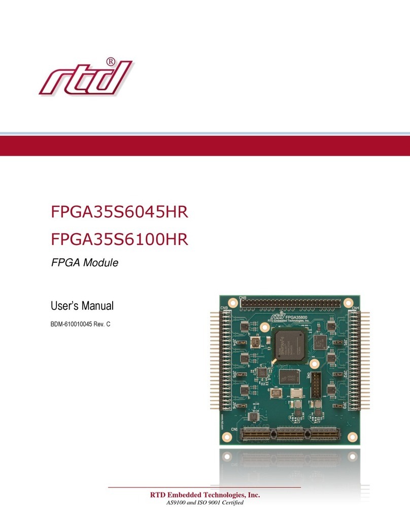
rtd FPGA35S6045HR User manual

rtd
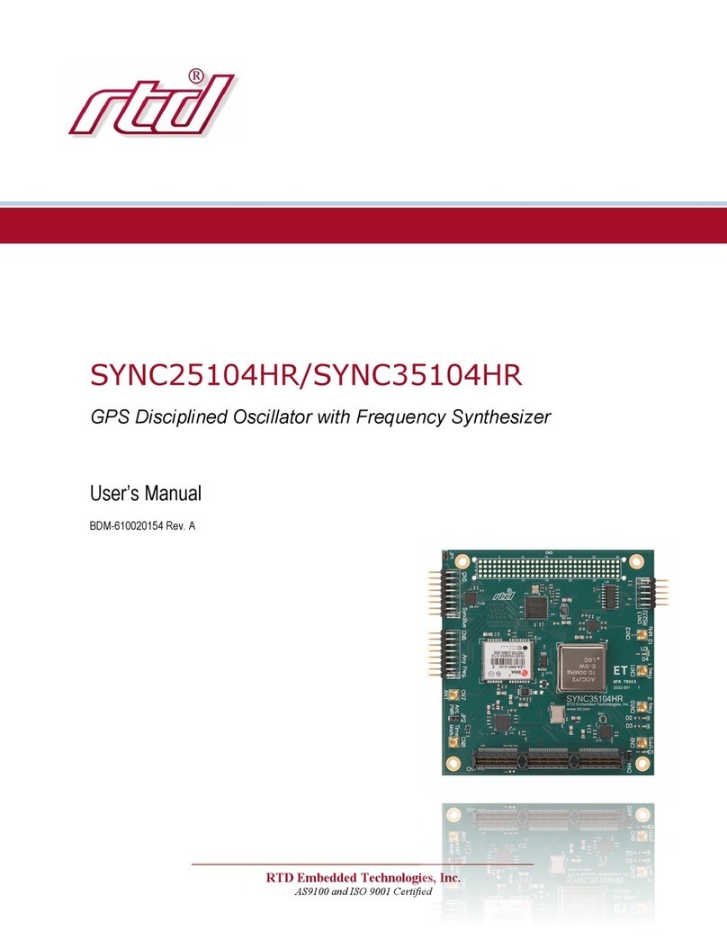
rtd SYNC25104HR User manual