Madrigal Audio Proceed User manual

PR O C E E D
DAP Digital Audio Processor

CAUTION
RISK OF ELECTRIC SHOCK
DO NOT OPEN
CAUTION: TO REDUCE THE RISK OF ELECTRICAL SHOCK, DO
NOT REMOVE COVER. NO USER-SERVICEABLE PARTS INSIDE.
REFER SERVICING TO QUALIFIED PERSONNEL.
WARNING: TO REDUCE THE RISK OF FIRE OR ELECTRIC SHOCK, DO
NOT EXPOSE THIS APPLIANCE TO RAIN OR MOISTURE.
NOTICE
This equipment has been tested and found to comply with the limits for a Class B digital device, pursuant to Part 15 of the
FCC Rules. These limits are designed to provide reasonable protection against harmful interference in a residential
installation. This equipment generates, uses and can radiate radio frequency energy and, if not installed and used in
accordance with the instructions, may cause harmful interference to radio communications. However, there is no guarantee
that interference will not occur in a particular installation. If this equipment does cause interference to radio or television
reception, which can be determined by turning the equipment on and off, the user is encouraged to try to correct the
interference by one or more of the following measures:
• Reorient or relocate the receiving antenna;
• Increase the separation between the equipment and the receiver;
• Connect the equipment into an outlet on a circuit different from that to which the receiver is connected;
• Consult the dealer or an experienced radio/TV technician for help.
CAUTION: Changes or modifications to this equipment not expressly approved by the manufacturer could void the user’s
authority to operate the equipment.
The information contained in the manual is subject to change without notice. The most current version of this manual will
be posted on our web site at http://www.madrigal.com.
The lightning flash with arrowhead symbol, within an equilateral triangle, is intended
to alert the user to the presence of uninsulated “dangerous voltage” within the
product’s enclosure that may be of sufficient magnitude to constitute a risk of electric
shock to persons.
The exclamation point within an equilateral triangle is intended to alert the user to the
presence of important operating and maintenance (servicing) instructions in the literature
accompanying the appliance.
Marking by the “CE” symbol (shown left) indicates compliance of this device with the EMC
(Electromagnetic Compatibility) and LVD (Low Voltage Directive) standards of the
European Community.

Important Safety Instructions
Please read all instructions and precautions carefully and completely before operating your DAP digital audio
processor.
1. ALWAYS disconnect your entire system from the AC mains before connecting or disconnecting
any cables, or when cleaning any component.
2. This product is equipped with a three-conductor AC mains power cord which includes an
earth ground connection. To prevent shock hazard, all three connections must ALWAYS be
used. If your electrical outlets will not accept this type of plug, an adapter may be purchased.
If an adapter is necessary, be sure it is an approved type and is used properly, supplying an
earth ground. If you are not sure of the integrity of your home electrical system, contact a li-
censed electrician for assistance.
3. AC extension cords are not recommended for use with this product. If an extension cord must
be used, be sure it is an approved type and has sufficient current-carrying capacity to power
this product.
4. NEVER use flammable or combustible chemicals for cleaning audio components.
5. NEVER operate this product with any covers removed.
6. NEVER wet the inside of this product with any liquid.
7. NEVER pour or spill liquids directly onto this unit.
8. NEVER block air flow through ventilation slots or heatsinks.
9. NEVER bypass any fuse.
10. NEVER replace any fuse with a value or type other than those specified.
11. NEVER attempt to repair this product. If a problem occurs, contact your Proceed®retailer.
12. NEVER expose this product to extremely high or low temperatures.
13. NEVER operate this product in an explosive atmosphere.
14. ALWAYS keep electrical equipment out of the reach of children.
15. ALWAYS unplug sensitive electronic equipment during lightning storms.

4
From all of us at Madrigal Audio Laboratories, thank you for choosing the
Proceed DAP digital audio processor.
A great deal of effort went into the design and construction of this precision
device. Used properly, it will give you many years of enjoyment.

5
Table of Contents
Unpacking and Placement ........................................................................ 6
Unpacking .......................................................................................................... 6
Placement .......................................................................................................... 6
Ventilation ........................................................................................................... 6
Operating Voltage ...................................................................................... 7
DAP bottom-panel label ............................................................................ 7
Special Design Features ............................................................................. 8
Superior isolation between sources .................................................................. 8
Fully balanced design ....................................................................................... 8
24 bit digital architecture and HDCD® compatibility ...................................... 8
Front Panel ................................................................................................... 9
Rear Panel .................................................................................................. 12
IR input tip polarity .................................................................................... 15
Using the DAP .............................................................................................. 17
Input Selection ................................................................................................... 17
Volume Control .................................................................................................. 17
Remote Control of the DAP ........................................................................18
Teaching DAP Front Panel Commands .......................................................... 18
Teaching Other DAP Commands ................................................................... 19
special commands table ......................................................................... 20
Care & Maintenance ................................................................................ 22
U.S. and Canadian Warranty .................................................................... 23
90-Day Limited Warranty .................................................................................. 23
Five Year Extended Warranty ........................................................................... 23
Obtaining Service ..................................................................................... 24
Specifications ............................................................................................ 25
Dimensions ................................................................................................ 26

6
Unpacking and Placement
Unpacking Unpack your Proceed®DAP digital audio processor and keep all packing mate-
rials for future transport. Locate and remove the AC power cord from the
cardboard slot it occupies within the shiping carton.
Placement Place the DAP near the source equipment, thus keeping interconnecting cables
(both digital and analog) reasonably short. It may be placed on a shelf or in a
cabinet where it’s convenient to operate.
Note that adequate clearance for the AC cord and connecting
cables must be left behind the DAP. We suggest leaving at least
three inches of free space behind the DAP to allow all cables
sufficient room to bend without crimping or undue strain.
Ventilation Be sure to allow 2 to 3 inches of clearance above the DAP to allow heat dissi-
pation through air circulation.
Mechanical drawings are included in this manual to facilitate special installa-
tions and custom cabinet work (see “Dimensions” at the end of this manual).
PRECAUTION
For your protection, review “Important Safety Instructions”
before you install your DAP.

7
Operating Voltage
The DAP digital audio processor is set at the factory (internally) for 100V, 120V,
200V, 220V, or 240V AC mains operation as appropriate for the country in which
it is to be sold. (230V only in European Union countries, in compliance with CE
regulations.) Make sure that the label on the rear of the DAP indicates the correct
AC operating voltage for your location. The operating voltage cannot be changed
by the user, and any attempt to do so will void the warranty.
If the voltage indicated is incorrect relative to that supplied in your area, see your
Proceed dealer.
DAP bottom-panel label
WARNING: BEFORE ATTEMPTING TO OPERATE THIS DEVICE,
REFER TO OWNER’S MANUAL FOR PROPER OPERATING
INSTRUCTIONS AND SAFETY PRECAUTIONS. HAZARDOUS
VOLTAGE AVAILABLE INSIDE; DISCONNECT AC – MAINS
CABLE BEFORE OPENING UNIT.
designed and manufactured in USA
MADRIGAL AUDIO LABORATORIES, INC.
No User Serviceable Components Inside.
For service, contact Madrigal Audio Laboratories or an Authorized
Dealer. Any modification to this equipment will void all warranties.
dap
S/N
PR O C E E D
R

8
Special Design Features
Congratulations on your purchase of the Proceed DAP. The Madrigal design
team is confident you will enjoy the outstanding performance of the DAP for
many years. In case you are interested in technical details, what follows is a
brief outline of some of the key technologies in your new processor.
Superior isolation
between sources
One of the advantages of a separate digital audio processor is that you can
take the money which might have otherwise been spent on several built-in
D/A converters and put it into one, superior processor which will enhance the
performance of all the transports with which it is used. Ironically, many out-
board processors fail to live up to this potential due to interference between
their various digital inputs.
The DAP provides outstanding isolation between its inputs, realizing the full
potential of the various digital transports with which it is used. In fact, all un-
selected digital inputs are capacitively shunted to ground upon entering the
DAP to prevent their interaction with any portion of the circuitry inside the
processor. As a result, the selected input effectively has the DAP “all to itself”
for its conversion to analog.
Fully balanced design The DAP is fully balanced in both the analog and digital domains. Even single-
ended digital inputs (anything other than the balanced aes/ebu standard) are
immediately converted to balanced signals before any further routing or pro-
cessing of the signal. All digital filtering and processing is implemented in a
balanced configuration, and conversion to analog is accomplished in two op-
posing polarity 18-bit converters per channel.
This approach maintains the integrity of the signal, reducing the opportunities
for music-destroying noise and digital artifacts to enter the signal path.
24 bit digital architecture
and HDCD®compatibility
All digital filtering and processing maintains a true 24-bit throughput capabil-
ity, providing greater digital resolution than any existing source component.
Even the most stringent requirements of professionals can easily be met with
this design.
In addition, the DAP also incorporates High Definition Compatible Digital®de-
coding to take full advantage of the increased resolution available from
HDCD®encoded 16-bit CDs. The High Definition Compatible Digital®format
retains much of the resolution inherent in professional twenty bit recordings
by encoding this information more efficiently within the sixteen bit space
available within the Compact Disc format.

9
PR O C E E D
dap
power
mute
mode
polarity
2 3 4 5
6
1
Front Panel
1 POWER & POWER LED
Assuming that the DAP’s power cord is connected to AC power, pressing
this latching power button connects the DAP to the AC mains and turns
on the unit. When power is restored after an interruption, the DAP will
be in standby; pressing any button will bring it out of standby.
While the DAP is in standby, the LED above the power button is red.
When the DAP is ready to operate (that is, when it is not in standby
mode), this LED is amber. Naturally, when AC power is off, the LED is
off.
The benefits of having then DAP always warmed up and ready to go
(and able to respond to a remote control) far outweigh the small amount
of power used. We recommend unplugging the DAP only when you will
be away from the house for an extended period of time (such as during
a vacation), or during electrical storms. The DAP may be left on at all
times, or can be forced back into standby with either a remote control
command or by pressing and holding the polarity button for s few sec-
onds.
2 MAIN DISPLAY
The main display provides information pertaining to the operation of the
DAP, and is used in conjunction with the up/down buttons beside it. Nor-
mally, the main display indicates the number of the selected digital input
(1 through 5) and the sampling frequency it is currently locked on (32,
44, or 48 kHz).

10
If an HDCD®recording is played, the display will flash hd and cd sev-
eral times, and then remain on hd to indicate that decoding is taking
place.
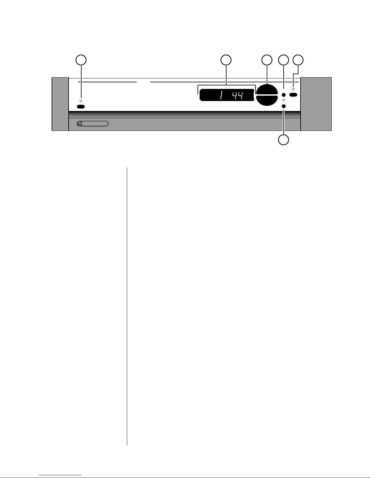
If the DAP is placed into its variable output mode, the main display will
indicate the relative volume on a scale of 0–99. (See the discussion of the
mode button, below.)
Finally, an infrared receiver and transmitter for remote control of the
DAP is positioned on the left side of the main display. Owners of learn-
ing remote controls such as those provided with Proceed preamplifiers
may transmit infrared control codes from the DAP to their learning re-
motes to “teach” the remote how to control the DAP. Subsequently, the
IR receiver in the main display will respond to the learning remote’s
commands for input selection, volume control, and certain other com-
mands. (See Remote Control of the DAP for more information.)
3 UP/DOWN BUTTONS
These up/down buttons are used to make adjustments on the DAP, in-
cluding source and volume selection. While the up/down buttons nor-
mally select the digital input (1 through 5) to be processed, they may
also be used to control the output level of the DAP. (See mode button,
below.)
4MODEBUTTON
Pressing this button toggles the DAP between input selection and vol-
ume selection modes.
Ordinarily, the DAP should be used at its maximum output level, with
volume control provided by a high quality active preamplifier which fol-
lows the DAP in the signal path. This approach provides the best sonic
performance as well as improved user convenience.
However, if for some reason a high quality active preamplifier is not
available, pressing the mode button will cause the DAP to change into its
variable output mode of operation, wherein the up/down buttons are
used to control the output level of the processor. Pressing the mode but-
ton a second time will return the DAP’s up/down buttons to their normal
input selection function.
5 MUTE
Pressing the mute button will reduce the main output level of the digital
audio processor by approximately 20 dB. Pressing the mute button a sec-
ond time will return the DAP to its previous output level. This function is
available at all times, whether the DAP is in input select or variable out-
put mode.
If you have the DAP in its variable output mode of operation and adjust
the volume with either the front panel buttons or a remote control while
in the mute mode, the digital audio processor will adjust its volume from
the muted volume and disengage the mute function. By so doing, the
DAP avoids sudden, unexpected changes in volume.

11
6 POLARITY
The DAP is a non-inverting device—that is, digital inputs which indicate
a positive voltage generate a positive analog output. Some recordings
may benefit from deliberately inverting the polarity (sometimes referred
to as “absolute phase”) by 180°to correct for a similar polarity inversion
incurred during the recording process. Pressing the polarity button will
illuminate the polarity indicator LED above the button, indicating that the
DAP is now inverting the polarity of the music signal. Pressing the
polarity button a second time will extinguish the LED and return the
DAP to its non-inverting state.
Pressing and holding the polarity button for several seconds will force
the DAP into standby.

12
PR O C E E D
R
d a p
by MADRIGAL AUDIO LABORATORIES
aes/ebu
analog outputs
~ ac mains
mains fuse:
.5A (250V) slo-blo 5x20mm
please see bottom panel for voltage and other information
spdifbnc eiaj st
digital inputs
PUSH
21
3
R
RL
Ldigital
out remote
IR
2
1 3 4 5 6 7 9 108
Rear Panel
Caution! Disconnect all associated equipment from the AC mains
BEFORE making any signal connections and applying power
to the DAP.
1 BALANCED ANALOG OUTPUTS
These outputs provide balanced analog audio (via cables equipped with
XLR-type connectors) to a preamplifier, integrated amplifier, or receiver
equipped with balanced inputs. Balanced interconnection between the
DAP and the component that follows it offers the best quality intercon-
nection and is highly recommended.
If you engage the variable output mode of operation of the DAP, these
outputs may be routed directly to a power amplifier that accepts bal-
anced inputs. This mode of operation is less desirable sonically than us-
ing a high quality active preamplifier, but may be advantageous under
some circumstances.
Caution! If you elect to use the variable output mode of the DAP to
allow direct-connection to a power amplifier, be certain to
turn the volume down to a low level before playing any
music. Sending a line-level (maximum volume) signal to
your power amplifier may endanger your loudspeakers.
The pin assignments of these XLR-type male outputs conform to the in-
ternational AES standard, and are as follows:

13
12
3
Pin 1: Signal ground
Pin 2: Signal + (non-inverting)
Pin 3: Signal – (inverting)
Connector ground lug: chassis ground
Refer to your preamplifier’s operating manual to verify that the pin as-
signments of its input connectors correspond to the DAP. If not, wire the
cable so that the appropriate output pin connects to the equivalent input
pin, or reverse the leads of both your speaker cables to “reverse the re-
versal” and restore correct polarity.
Connect the right-channel and left-channel balanced outputs of the DAP
to the corresponding inputs on your preamplifier (or power amplifier if
you are using the variable output mode of the DAP).
2 SINGLE-ENDED ANALOG OUTPUTS
These outputs provide single-ended analog audio (via cables equipped
with RCA-type connectors) to a preamplifier, integrated amplifier, or re-
ceiver equipped with single-ended inputs. Most components accept this
type of output.
If you engage the variable output mode of operation of the DAP, these
outputs may be routed directly to a power amplifier. This mode of op-
eration is less desirable sonically than using a high quality active pream-
plifier, but may be advantageous under some circumstances.
Caution! If you elect to use the variable output mode of the DAP to
allow direct-connection to a power amplifier, be certain to
turn the volume down to a low level before playing any
music. Sending a line-level (maximum volume) signal to
your power amplifier may endanger your loudspeakers.
Connect the right-channel and left-channel single-ended outputs of the
DAP to the corresponding inputs on your preamplifier (or power ampli-
fier if you are using the variable output mode of the DAP).
3 DIGITAL OUTPUT
This output provides digital audio (via a 75Ωcable equipped with RCA-
type connectors) to the digital input of a DAT, CD-R, MD, DCC, or any
other component that accepts an S/PDIF electrical digital input. It auto-
matically sends a copy of the currently selected digital source’s
datastream to the connected device for recording or further digital pro-
cessing.
Connect the digital output of the DAP to the RCA input of your digital
recorder using a high quality 75Ωcable such as Madrigal MDC-2.

14
4 AES/EBU DIGITAL INPUT
This input accepts digital audio conforming to the 110ΩAES/EBU digital
interface standard (via a cable equipped with XLR-type connectors) from
the digital output of a digital FM tuner, compact disc player, laserdisc
player, or digital audio recorder.
The pin assignments of these AES/EBU XLR-type female input connec-
tors are:
21
3
Pin 1: Shield
Pin 2: Digital + (non-inverting)
Pin 3: Digital – (inverting)
Connector ground lug: chassis ground
These pin assignments are consistent with the standards adopted by the
Audio Engineering Society and the European Broadcast Union. Refer to
the operating manuals of your digital sources to verify that the pin as-
signments of their output connectors correspond to the DAP. If not, wire
the cables so that the appropriate output pin connects to the equivalent
input pin.
Connect the AES/EBU output of your digital source component to the
AES/EBU (XLR) input of the DAP using a high quality 110Ωcable such
as Madrigal MDC-1.
5 BNC DIGITAL INPUT
This input accepts digital audio conforming to the 75ΩS/PDIF digital in-
terface standard (via a cable equipped with BNC-type connectors) from
the digital output of a digital FM tuner, compact disc player, laserdisc
player, or digital audio recorder.
Connect the digital output of your digital source component to the BNC
input of the DAP using a high quality 75Ωcable such as Madrigal
MDC-2.
6 SPDIF (RCA) DIGITAL INPUT
This input accepts digital audio conforming to the 75ΩS/PDIF digital in-
terface standard (via a cable equipped with RCA-type connectors) from
the digital output of a digital FM tuner, compact disc player, laserdisc
player, or digital audio recorder.
Connect the digital output of your digital source component to the RCA
input of the DAP using a high quality 75Ωcable such as Madrigal
MDC-2.
7 EIAJ DIGITAL INPUT
This input accepts digital audio conforming to the EIAJ optical (some-
times called “Toslink”) digital interface standard from the EIAJ digital out-
put of a digital FM tuner, compact disc player, laserdisc player, or digital
audio recorder.
Connect the digital output of your digital source component to the EIAJ
input of the DAP using a high quality EIAJ optical cable.

15
8 ST DIGITAL INPUT
This input accepts digital audio conforming to the ST optical (sometimes
called “AT&T”—ST is a trademark of AT&T and the correct designation
for the interface) digital interface standard from the ST digital output of a
digital FM tuner, compact disc player, laserdisc player, or digital audio
recorder.
Connect the digital output of your digital source component to the ST
input of the DAP using a high quality optical cable.
9REMOTEIR
A 1⁄8" (3.5 mm) “mini” jack in the lower right corner of the rear panel
provides direct access to the infrared control circuitry of the DAP. This
remote IR input facilitates a wide range of installation options. If desired,
the DAP may be placed inside a cabinet or outside the normal line-of-
sight in the listening area, with the controlling IR signal being relayed to
the DAP by any of a number of commercially-available IR repeaters.
The incoming signal for the remote IR input should conform to widely-
accepted IR repeater standards: that is, the signal present should be be-
tween 3-12 volts DC at less than 100 mA current, with a positive tip po-
larity, as shown below:
IR input tip polarity
+– 3-12 volts @ less
than 100 mA
Your Proceed dealer can help you take advantage of these design fea-
tures to maximize your system’s versatility. (Note that the DAP is not sup-
plied with an infrared remote control. Instead, it can teach a learning
remote such as those provided with Proceed preamplifiers the needed
commands, reducing the overpopulation of remote controls on your coffee
table by one. See “Remote Control of the DAP” for more information.)
10 AC MAINS FUSE AND AC POWER RECEPTACLE
An ac mains fuse is provided which disconnects the DAP from the wall
outlet’s AC power under fault conditions. If this fuse should “blow” for
any reason, replace it only with the same value fuse (0.5A/250V slo-blo
5x20mm). If it blows a second time, please contact your Proceed dealer
for service.
Caution! Replacing the ac mains fuse with a anything other than the
recommended value fuse will places the DAP at substantial
risk of damage!

16
Plug the supplied three-prong power cord into the ac power input re-
ceptacle provided before plugging the power cord into the wall. If a
longer AC power cord is required for your application, be sure to use a
three-conductor power cord which conforms to IEC standards.
Caution! The Proceed DAP has been safety-tested and is designed
for operation with a three-conductor power cord. Do not
defeat the “third pin” or earth ground of the AC power cord.

17
Using the DAP
Input Selection The DAP has five digital inputs. Using the up/down buttons, you may scroll
through the five inputs in either direction. The number of the selected input
will be shown in the center of the main display,while the sampling frequency
the DAP has locked onto is displayed on the right side. (If no digital audio sig-
nal is available, the sampling frequency portion of the display will show two
hyphens (“- -”) to indicate the lack of DAS.) The digital data from the selected
input is also automatically made available to whatever device is connected to
the DAP’s digital output.
Volume Control The DAP may be placed in its variable output mode of operation by pressing
the mode button, at which time the sampling frequency display within the
main display will be replaced by a relative volume scale which runs from 0-99.
Through most of the useful range of this scale, the increments are slightly
more than 1⁄2dB per step, providing excellent volume resolution.
Many audiophiles assume that having fewer components in the signal path au-
tomatically and always means better sound quality: simpler is better. While
there is some merit to this concept, it is often taken too far. Specifically, vol-
ume control is best done in the analog domain, in a high quality active pream-
plifier. The reasons for this fact are fairly straightforward.
• “Digital” volume controls (volume control performed in the digi-
tal domain)—even extremely good ones such as the implemen-
tation in the DAP—reduce volume by scaling down the numbers
which represent the music. In this process, some low level infor-
mation is inevitably lost. While this loss can be partially miti-
gated by techniques such as those in the DAP, it is impossible to
completely avoid some loss of musical information if any signifi-
cant volume reduction is performed in the digital domain.
• Volume controls performed in the analog side of the circuit that
are passive in nature (so-called “passive preamps”) vary the ef-
fective output impedance of the processor by inserting an addi-
tional, variable resistance between the processor and the power
amplifier. This variable output impedance makes these systems
unduly cable sensitive and often changes the sound of the sys-
tem as a function of the volume setting. This inconsistency can
hardly be considered high performance.
• By contrast, a high quality active preamplifier serves as a buffer
between all sources and the power amplifier and provides con-
sistently high performance at all volume levels and with all
sources.
For the reasons outlined above, it is recommended that the variable output
mode of the DAP be used as a “stopgap” measure rather than as the primary
mode of operation. If your preamplifier fails, or if you are still saving up for a
high quality preamplifier, the DAP’s variable output level circuitry will provide
performance which is unsurpassed among digital volume controls. For the fin-
est musical performance (particularly reproduction of low-level information
such as hall ambience, etc.), use a high quality preamplifier such as the Pro-
ceed PRE or PAV, and leave the output of the DAP at maximum.

18
Remote Control of the DAP
The DAP includes both an infrared receiver and an infrared transmitter. With
this capability, it can “teach” a learning remote control such as those provided
with Proceed preamplifiers any commands that might be needed for remote
operation. These include input selection, volume control, mode, polarity, etc.
Specifically, the DAP can send all of the necessary IR commands from its main
display window, enabling you to teach a learning remote any or all of its pre-
programmed commands, as well as some optional special commands that are
available to solve specific installation-related problems.
The DAP has two special modes of operation into which is may be placed in
order to facilitate the “teaching” of remote control commands to a learning re-
mote control. The first allows you to easily teach the commands for which
there are corresponding front panel buttons. The second allows you to teach
“special” commands to the remote control for which there are no correspond-
ing front panel buttons.
Teaching DAP Front
Panel Commands
1 PRESS AND HOLD THE MODE BUTTON UNTIL “L 00” APPEARS IN THE
DISPLAY
A momentary press of the mode button will, of course, simply toggle the
DAP’s up/down buttons between input selection and volume control
modes. When you “camp on” the mode button instead, the DAP will
wait for a few seconds to make sure that your press-and-hold action is
quite deliberate, and then enter a teaching mode which allows you to
program a learning remote control with infrared (IR) commands. The
DAP’s main display will show the letter “L” (for “Learn”) and a two-digit
number when in this mode.
The DAP will display a “L 00” code when it has entered its teaching
mode and is ready to help the remote control learn the commands that
correspond to the DAP’s front panel buttons. If no further buttons are
pressed within approximately ten seconds, the DAP will “time out” and
return to normal operation.
2 PRESS ANY FRONT PANEL BUTTON TO CAUSE THE DAP TO SEND THE
CORRESPONDING IR COMMAND
Line up the IR window of your remote control with the left side of the
main display of the DAP, at a distance of approximately 6"-12". Select the
to-be-learned button on the remote, then press the corresponding button
on the DAP to fire the appropriate IR code. (Tip: most learning remotes
need to be held fairly still while they learn new IR commands; movement
can garble the received IR.)

19
Notice that the mute LED changes its status (either on or off) briefly after
you press a button. This LED change indicates that the DAP is transmit-
ting the command which corresponds to the button you just pushed. You
may repeat this process until all commands have been learned by your
remote control. The up and down buttons cause a longer stream of IR
codes to be sent to your learning remote to enable it to “learn” the press-
and-hold function one would use when making large changes in vol-
ume.
(If you are uncertain as to how to prepare your remote control for learn-
ing new commands, refer to the instructions provided with the remote
control.)
3 REPEAT THE PROCESS OF “TEACHING” NEW COMMANDS TO THE
VARIOUS BUTTONS ON YOUR REMOTE CONTROL UNTIL ALL FRONT
PANEL COMMANDS HAVE BEEN LEARNED BY YOUR REMOTE
If you take longer than approximately ten seconds between front panel
button pushes, the DAP will time out and return to normal operation. If
this occurs, return to step #1 in this section.
4 WHEN FINISHED, EXIT THE PROGRAMMING MODE BY ALLOWING THE
DAP TO “TIME OUT,” OR PRESS AND HOLD THE MODE BUTTON
The DAP will “time out” and return to normal operation after approxi-
mately ten seconds of inactivity on your part. Alternatively, you may
press and hold the mode button to return to normal operation if you
wish to hurry it along.
You may wish to continue on to the next section to teach a remote con-
trol the DAP’s special commands, in which case you should go directly
to the next section. At some point, however, you should test all your
newly “learned” commands to ensure that they were “learned” correctly.
Teaching Other
DAP Commands
As mentioned above, the DAP has the capability to teach learning remote con-
trols special commands for which there are no front-panel counterparts. These
include commands that provide direct access to the various inputs by number,
and display on/off modes.
In addition, there are several “hard assignment” commands available in the
DAP which will place it into a certain mode of operation regardless of its cur-
rent state. For example, a hard assignment command to enter standby will
leave the DAP in standby if already there, or switch it to standby if it is cur-
rently operating. This type of hard assignment command is especially helpful
when you do not necessarily know the current status of the DAP, as might be
the case in a multi-room home entertainment system (for example).

20
1 PRESS AND HOLD THE MODE BUTTON UNTIL “L 00” APPEARS IN THE
DISPLAY
A momentary press of the mode button will, of course, simply toggle the
DAP’s up/down buttons between input selection and volume control
modes. When you “camp on” the mode button instead, the DAP will
wait for a few seconds to make sure that your press-and-hold action is
quite deliberate, and then enter a teaching mode which allows you to
program a learning remote control with infrared (IR) commands. The
DAP’s main display will show the letter “L” (for “Learn”) and a two-digit
number when in this mode.
The DAP will display a “L 00” code when it has entered its teaching
mode and is ready to help the remote control learn the commands that
correspond to the DAP’s front panel buttons. If no further buttons are
pressed within approximately ten seconds, the DAP will “time out” and
return to normal operation.
2 PRESS AND HOLD THE MUTE BUTTON UNTIL “L 01” APPEARS IN THE
DISPLAY
By holding this button for several seconds, you are instructing the DAP
to give you access to programming options beyond those represented by
the front panel buttons.
The following table lists the special commands that are available for the
DAP. In the second column are the programming “codes” used in the
main display to represent those special commands.
special commands table
hard assignment for operate L 01
hard assignment for standby L 02
display off L 03
display on L 04
volume mode L 05
input select mode L 06
–10 step in volume control L 07
+10 step in volume control L 08
toggle display on/off L 09
select input 1 L 10
select input 2 L 11
select input 3 L 12
select input 4 L 13
select input 5 L 14
3 USE THE UP/DOWN BUTTONS TO SELECT THE CODE THAT CORRE-
SPONDS TO THE SPECIAL FUNCTION YOU WOULD LIKE TO TEACH
YOUR REMOTE CONTROL
Pressing the “up” button will increase the program code number by one;
“down” will decrease the program code number by one. Select the de-
sired code number from the list above.
Other manuals for Proceed
1
Table of contents