www.madur.com Manual maMoS100/200/300/400
Contents
1. Introduction....................................................................................................................4
2. Package content............................................................................................................5
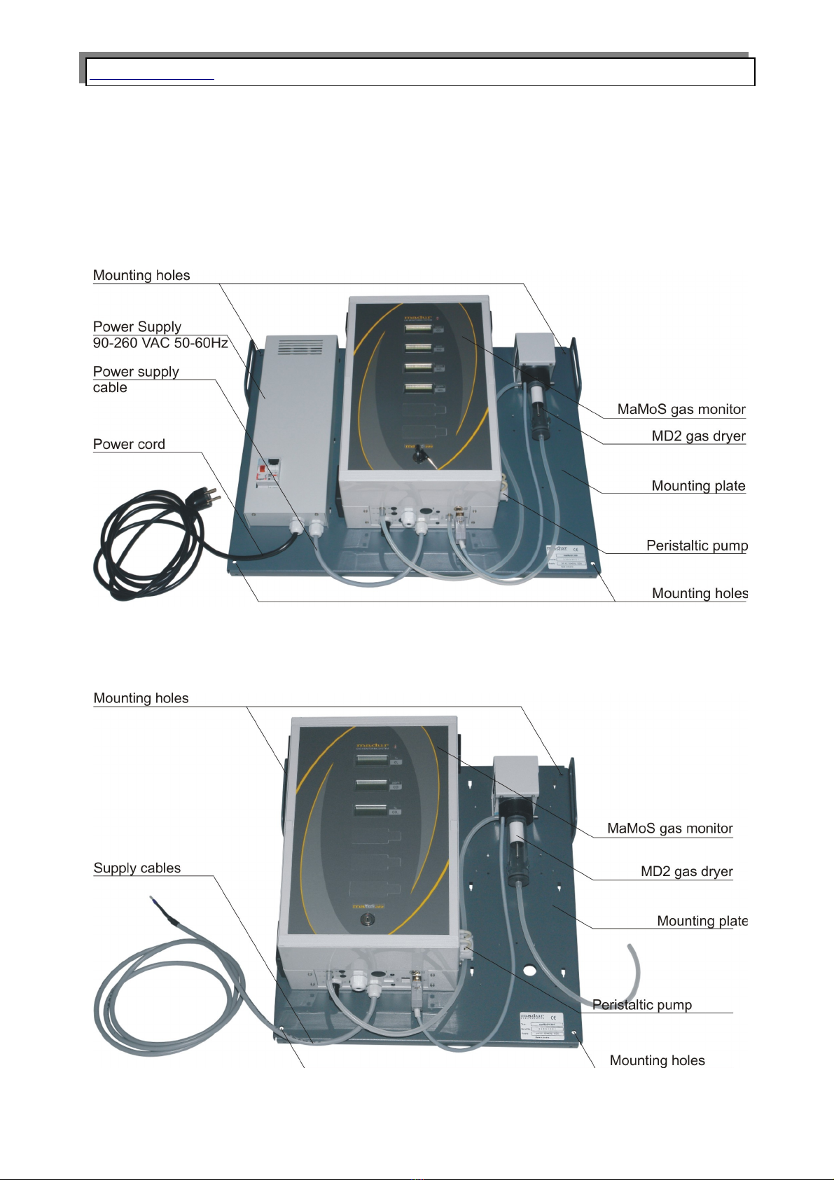
3. Monitor construction.....................................................................................................6
3.1. Casing.....................................................................................................................7
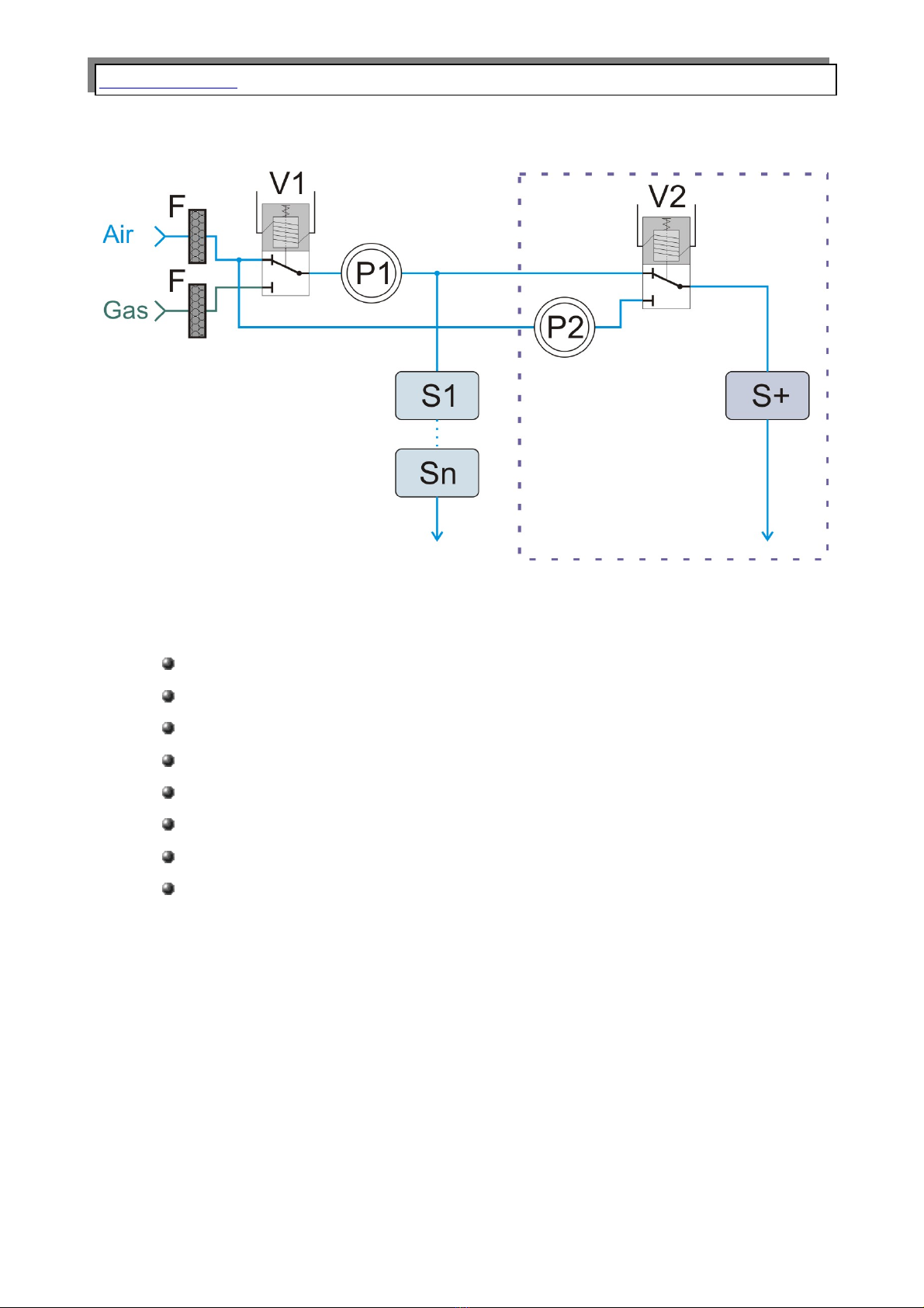
3.2. Gas channel............................................................................................................9
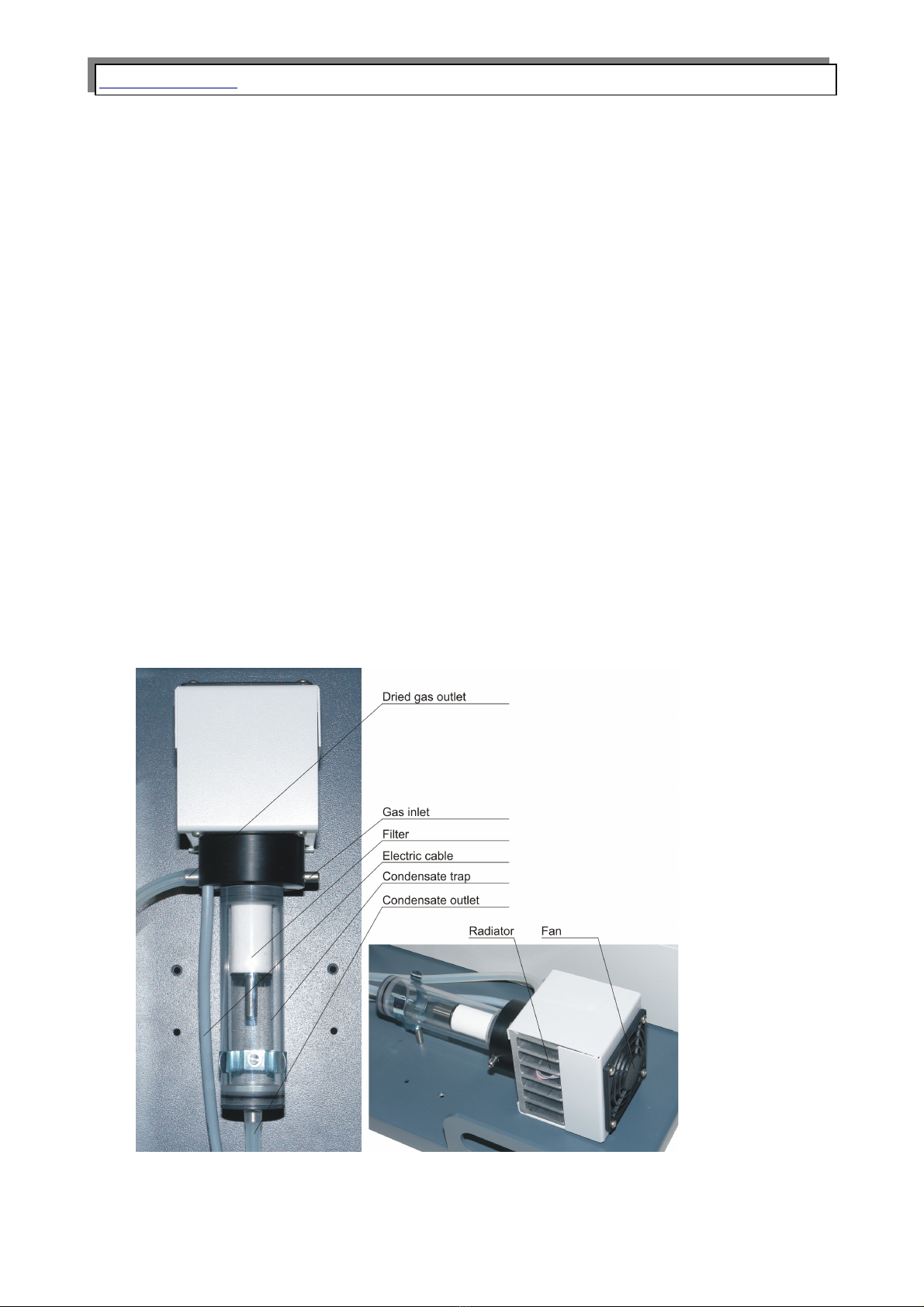
3.2.1. Gas dryer with filter......................................................................................10
3.2.2. Peristaltic um ............................................................................................11
3.2.3. Solenoid valve...............................................................................................12
3.2.4. Gas um ......................................................................................................12
3.2.5. Gas sensors..................................................................................................12
3.3. Electric connectors of the monitor....................................................................13
3.3.1. Digital in uts.................................................................................................13
3.3.2. Analogue out uts.........................................................................................14
3.3.3. Digital out ut (PWM)....................................................................................15
3.3.4. Relay out uts (o tional)...............................................................................16
3.4. Monitor ower su ly..........................................................................................17
3.5. Configuration ossibilities..................................................................................18
3.5.1. Ty es of the measured gases.....................................................................18
3.5.2. Additional and o tional equi ment............................................................19
4. Monitor installation.....................................................................................................20
4.1. Connecting the monitor.......................................................................................21
4.1.1. Connecting the electric wires......................................................................21
4.1.2. Connecting the gas hoses...........................................................................24
4.2. First start-u .........................................................................................................27
5. O eration......................................................................................................................27
5.1. Basic o eration....................................................................................................27
5.2. Monitor function...................................................................................................28
5.2.1. Cyclic work mode.........................................................................................28
5.2.2. Scheduled work mode..................................................................................30
5.3. Communication with monitor.............................................................................31
5.3.1. Monitor network (RS485).............................................................................32
5.3.2. Communication via USB ort......................................................................33
5.3.3. Communication via Ethernet.......................................................................37
5.4. MMC module. .......................................................................................................41
5.4.1. Possible flashing sequences of the MMC control diode lam ................44
5.4.2. Formatting SD / MMC card in FAT-16 file system.....................................44
5.5. U dating the monitor's firmware........................................................................45
5.5.1. The rocedure of u dating firmware..........................................................45
5.6. Flow velocity measurement................................................................................49
5.7. Re lacing the dryer filter.....................................................................................51
5.7.1. Re lacing the filter in MD2 dryer................................................................51
5.7.2. Re lacing the filter in MD3 dryer................................................................53
5.8. Re lacing the head of the eristaltic um ......................................................54
6. Presenting the results.................................................................................................54
6.1. Calculating the results.........................................................................................55
2