madur electronics GA-60 User manual

GAS ANALYSER
GA-60
Manual
Version: 3.1
9/2013
Index

www.madur.com Manual GA-60
1. Introduction....................................................................................................................3
2. Package Contents.........................................................................................................4
3. General information......................................................................................................5
4. Construction..................................................................................................................6
4.1. Front anel..............................................................................................................6
4.2. Gas channel............................................................................................................7
4.2.1. Gas robe........................................................................................................7
4.2.2. Gas um ........................................................................................................7
4.2.3. Electrochemical sensors...............................................................................7
4.2.4. NDIR sensors..................................................................................................7
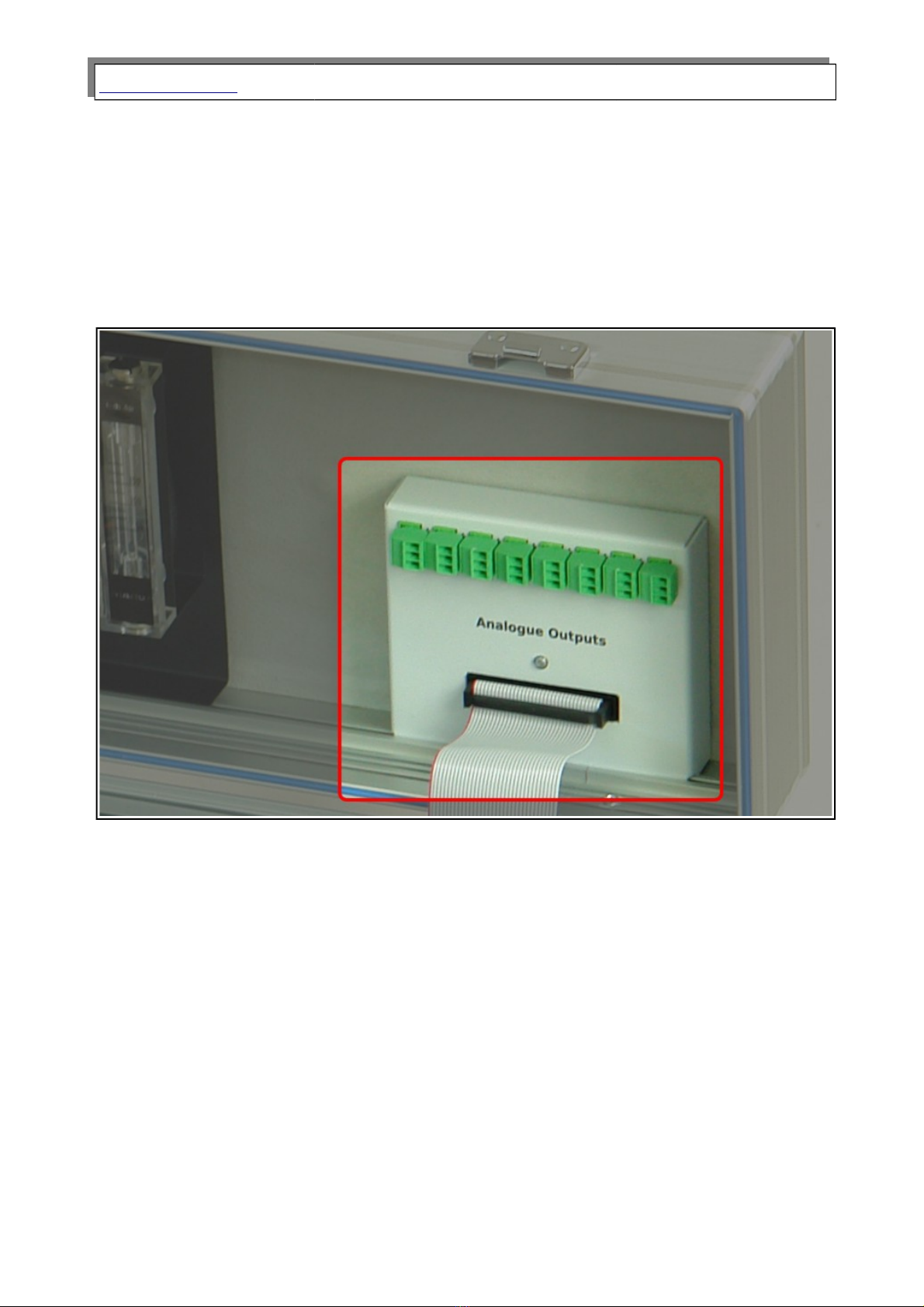
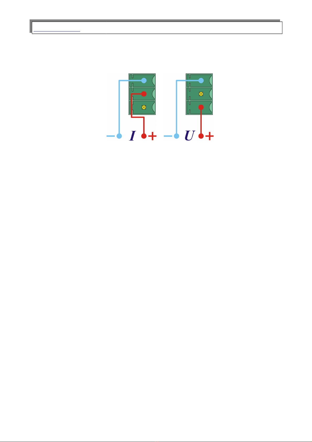
4.3. Analogue out uts...................................................................................................8
4.4. Power.......................................................................................................................9
5. Working with the analyser..........................................................................................10
5.1. Starting u the analyser......................................................................................10
5.2. Pre aration for measurements...........................................................................11
5.3. Measurements screens.......................................................................................11
5.3.1. Measurements arameters screens...........................................................11
5.3.1.1. NO in NOx................................................................................................13
5.3.2. Results screens............................................................................................14
5.3.2.1. Results screen number 4.......................................................................16
5.3.3. Saving o tions screen.................................................................................17
5.3.3.1. Start function key....................................................................................19
5.3.3.2. Function key O tions.............................................................................21
5.3.3.3. MMC/SD....................................................................................................22
5.3.4. O eration screen..........................................................................................25
5.3.4.1. Soot test...................................................................................................27
5.3.5. Print o tions..................................................................................................29
5.3.6. Menu...............................................................................................................30
5.3.6.1. Measurement arameters......................................................................30
5.3.6.2. Settings....................................................................................................31
5.3.6.3. Internal memory......................................................................................32
5.3.6.4. Gas conditioner.......................................................................................33
5.3.6.5. Clock / Calendar......................................................................................34
5.3.6.6. Service......................................................................................................35
5.3.6.6.1. Info....................................................................................................36
5.3.6.6.2. Control list........................................................................................36
5.3.6.6.3. IR sensors calibration.....................................................................36
5.3.6.6.4. ElChem sensors calibration...........................................................39
5.3.6.6.5. Pressure calibration........................................................................40
5.3.6.6.6. Restore settings of the Multi module............................................42
5.4. Ending work with the analyser...........................................................................42
6. TIPS ON HOW TO USE THE ANALYSER...................................................................42
6.1. Electrochemical gas sensors.............................................................................42
6.2. Service...................................................................................................................43
7. Com uter software......................................................................................................43
2

www.madur.com Manual GA-60
1. INTRODUCTION
Congr tul tions on your purch se of the microprocessor-controlled flue g s
n lyser
GA-60
It is high qu lity instrument produced using the l test technic l discoveries. The
GA-60 is e sy to use. You lso h ve the possibility of using the extr c p bilities of this
n lyser, of ex mining me surement results, checking service interv ls nd m ny others.
Ple se re d the oper ting m nu l c refully. It cont ins v lu ble tips nd inform tion for
problem-free oper tion. Regul r m inten nce will help to keep your n lyser re dy for
use t ll times.
3

www.madur.com Manual GA-60
3. GENERAL INFORMATION
GA-60 g s n lyser c n be equipped with up to 6 electrochemic l sensors nd 2
NDIR g s sensors. Depended on the configur tion, the n lyser c n me sure the
concentr tion of the following g ses: O2, CO2, CH4, CO, NO, NO2, NOx, SO2, H2S, H2,
NH3, Cl2, HCl. CO2, CH4 g ses re me sured using optic l sensors (NDIR – non-
dispersive infr -red). All other g ses re me sured using electrochemic l cells. G s
concentr tions c n be presented s:
volume concentr tion (% or ppm)
m ss concentr tion (mg/m3)
m ss concentr tion referred to oxygen (mg/m3)
Addition lly, the n lyser me sures fumes temper ture, mbient temper ture
(with use of thermocouple nd PT500 sensor), tmospheric pressure nd differenti l
pressure. B sed on the me surement d t nd on the fuel p r meters, the n lyser c n
c lcul te the following v lues:
st ck loss
loss by incomplete combustion
efficiency
excess ir (l mbd )
All the me sured nd c lcul ted v lues c n be presented on the n lyser's
displ y, stored in reports on MMC/SD memory c rd or in the n lyser's intern l memory.
They c n lso be represented by electric l sign ls through n logue outputs (current or
volt ge).
5

www.madur.com Manual GA-60
4. CONSTRUCTION
4.1. Front panel
Dr wing 1. Front anel of the GA-60 gas analyser
The dr wing bove shows the front p nel of the n lyser with its essenti l p rts:
1. G seous connection of g s filter th t is inst lled in c se's lid.
2. MMC / SD c rd's slot – this memory c rd is used for s ving me surements in
form of reports, th t c n be l ter viewed nd processed on PC computer.
3. Displ y – ¼ VGA monochrom tic LCD displ y to present results of
me surements. For better viewing it is equipped with b ck-light nd
contr st control. At the bottom of the screen there is function keys'
description b r (10). Function keys m y ch nge depending on the screen the
user is viewing.
4. Numeric keybo rd, llows to enter v lues while oper ting.
5. Printer – llows immedi te ccess to p per me surements results. 57 mm
st nd rd p per comes out of the n lyser with speed of 2.5 lines per second.
6. An lysers ON/OFF switch – mech nic l power switch.
7. Probes connector – llows n lyser to work with g s probe.
8. G s inlet – connection for probes g s hose.
9. 4 direction l buttons ( rrow keys) – llow e sy movement through n lysers
menu screens.
10. 4 function keys – f st ccess to progr ms functions. E ch of the keys h s its
function's n me visible on the screen, bove the key.
11. Pressure connectors – for me surement of g s pressure nd chimney dr ft.
6

www.madur.com Manual GA-60
12. Ambient temper ture probes connector – llows to work with the PT500
probe.
13. Communic tion c ble’s connector – n lyser c n be set nd checked from
computer. A speci l RS-232C c ble nd softw re re included. Softw re
m kes working with the n lyser nd setting up clients nd fuels d t b ses
e sier.
4.2. Gas channel
4.2.1. Gas probe
G s s mple is collected with g s probe (usu lly equipped with temper ture
sensor). Typic l probe lengths re: 150mm, 300mm, 750mm, 1500mm.
4.2.2. Gas pump
GA-60 is equipped with g s pump (efficiency – 90l/h) th t provides g s s mple
to the sensors. It is possible to m nu lly switch the pump off (for ex mple when n lyser
is to work with extern l g s dryer equipped with its own pump, like PGD-100).
4.2.3. Electrochemical sensors
Electrochemic l sensors re used for ll oxygen me surements nd sometimes
for some other g ses. Oxygen sensor is c libr ted with ir within initi l c libr tion.
Other sensors re only zeroed during th t time.
4.2.4. NDIR sensors
An lyser c n be equipped m xim lly with 2 NDIRs. These sensors re used for
CO2 nd CH4 me surements.
7

www.madur.com Manual GA-60
4.3. Analogue outputs
GA-60 c n be equipped with 16 n logue outputs (8 current nd 8 volt ge
ones). An logue outputs module is mounted on the right side in the n lysers lid (shown
in Dr wing 2.). Connectors re numbered 1÷8 st rting from the left. E ch connection h s
p ir of outputs – one current nd one volt ge.
Dr wing 2. Localisation of the analogue out uts module in the analysers lid.
With use of included softw re e ch output c n be ssigned to one of me sured
or c lcul ted v lue. Then current or volt ge in the ppointed output will be proportion l to
the me sured g s p r meter. Progr m lso llows to specify r nge within which the
v lue of current will ch nge.
Volt ge r nges in the volt ge outputs (U1÷U8) c n be set in the progr m to 0÷5V
or 0÷10V. In simil r w y current r nge c n be set to 0÷20mA or 4÷20mA.
8

www.madur.com Manual GA-60
Extern l devices c n be connected to these n logue outputs with use of n
electric l wire (with m xim l di meter of 1mm2) th t h s to be screwed to the
connector. In e ch connector wiring looks like on the pictures below.
) b)
Dr wing 3. Wiring in analogue out uts: a) current out uts, b) voltage out uts.
4.4. Po er
An lyser GA-60 is to be powered from the m ins power supply (110VAC or
230VAC). It c n lso be powered from its own built-in rech rge ble b ttery for up to 12
hours. This b ttery ch rges whenever the n lyser is connected to the m ins power
supply.
9

www.madur.com Manual GA-60
5. WORKING WITH THE ANALYSER
5.1. Starting up the analyser
To st rt up the n lyser you h ve to use the switch pl ced on the right side of the
front p nel. If you did not use the m ins power cord, the n lyser will st rt, using its built-
in rech rge ble b ttery. When the power cord is used, the n lyser will ch rge the
b ttery reg rdless from the power switch being in ON or OFF position.
At first, welcome screen will be displ yed (like the one below) nd fterw rds n
inform tion bout process of g s sensors zeroing should be visible.
Dr wing 4. Welcome screen visible straight after the analyser is starts.
Zeroing procedure t kes 120 seconds nd is necess ry for me surements
precision. A countdown timer visible on the screen shows the time rem ining to the end of
this process. Afterw rds the n lyser is re dy to work, with screen of me surement's
p r meters displ yed.
Dr wing 5. Resetting screen with countdown timer.
10

www.madur.com Manual GA-60
Attention!
Fresh air must be rovided to the analyser through the analyser's
robe throughout the whole rocess of zeroing.
If n auto-start option is chosen in the s ving options, nd n SD/MMC c rd is in
the c rd port, the third screen visible will include request for clients number for which ll
following me surements will be c rried (you c n find more inform tion bout uto-st rt in
ch pter 5.3.3.3)
5.2. Preparation for measurements
Before you st rt the n lyser you should set up complete me suring module:
Connect probe pipe with probe holder
Connect g s hose to the n lyser (both connectors, g s nd electric)
Connect the n lyser to the m ins power supply (if n lyser is to work from
the b ttery this step c n be skipped)
St rt the n lyser with the switch on the front p nel (right side of the p nel,
close to the h ndle)
Then process of zeroing the sensors will st rt nd fter bout 2 minutes the
n lyser is re dy to work.
Attention!
Fresh air must be rovided to the analyser through the analyser's
robe throughout the whole rocess of zeroing.
5.3. Measurements screens
5.3.1. Measurements parameters screens
Me surements p r meters screen is the first th t you c n see when the n lyser
is re dy to work. You c n lso get to this view from Results screens or Menu screens.
11

www.madur.com Manual GA-60
Dr wing 6. Measurements arameters screen.
From this pl ce you c n ch nge n lysers me surements p r meters. Use rrow
keys up/down to move between different settings. Keys left/right will llow ch nging
chosen p r meters v lue (th t is highlighted with sm ll rrow on the left side of the
screen). You c n lso use function key change to incre se selected v lue.
You c n ch nge below mentioned p r meters:
Averaging time – time interv l for which ll me surement results will be
rec lcul ted ver ged nd displ yed. GA-60 re ds me surements results
every 2 seconds nd stores the l st 90 me surements in its inner memory.
An lyser c n displ y v lue ver ged for chosen time from these stored
results. You c n set the ver ging time to one of these v lues: 2s, 6s, 10s,
20s, 30s, 60s, 120s, 180s.
Attention!
This o eration will change the averaging time globally. If the
averaged results are being saved, all of them will be stored with the
new time set.
Measurement time XL – it is time of single XL me surement. GA-60
me sures for the set time, ver ges the result nd stores it s report in its
inner memory or on SD/MMC c rd. XL time c n be set to: 10s, 20s, 30s,
1min, 2min, 5min, 10min, 15min, 20min, 30min.
NO in NOx – llows setting v lue of percent ge content of NO in NOx (nitric
oxide, on sep r te screen NO in NOx). If the n lyser is equipped with NO2
sensor, NO in NOx setting will not be visible.
12

www.madur.com Manual GA-60
Reference O – reference v lue of oxygen used for c lcul tions of rel tive
m ss concentr tions.
Fuel – currently used fuel. N me of the fuel is displ yed in the line below the
setting n me. GA-60 stores 14 different fuel settings, of which 10 re f ctory
def ults nd 4 c n be set by the user.
The l st 3 settings re used for c lcul tions, consequently should st y set to
ctu l v lues to llow correct nd precise me surements results.
One c n le ve the me surements p r meters screen with the ESC key, this will
tr nsfer Results screens screen.
5.3.1.1. NO in NOx
Pressing the change function key in setting NO in NOx on the Measurement
parameters will m ke the screen below ppe r:
Dr wing 7. NO in NOx value setting screen.
This v lue c n be ch nged with the numeric keyp d or with the rrow keys –
left/right key will ch nge the indic tor position, up/down key will ch nge the highlighted
v lue.
NO in NOx v lue is displ yed in % nd should be set within the r nge of 50% -
100%. In c se it is set bove or lower, the n lyser will utom tic lly ch nge the v lue to
50% or 100%. In situ tion when the n lyser is equipped with NO2 sensor, NO in NOx
setting will not be displ yed.
13

www.madur.com Manual GA-60
5.3.2. Results screens
GA-60 n lyser displ ys me surements results on 4 screens. You c n switch
between them by pressing up nd down rrow keys. The computer softw re c n be used
for setting order in which the results will ppe r on the 4 results screens.
Dr wing 8. Exam le of the results screen
A st tus b r is visible in the top of the results screen. Inform tion v il ble:
1 – number of the results screen; 4 screens re v il ble. You c n ch nge
the screen by pressing up/down rrow key. Types of displ yed p r meters
differ depending on the n lysers configur tion.
M003 – multiple s ving me surement enrolling; Number represents v lue of
rem ining s vings to be done.
F1 – ID number of fuel set; ch nge c n be done from Me surements
p r meters screens.
T= s – ver ging time; ch nge c n be done from Me surements p r meters
screens. If working time of the n lyser is shorter th n ver ging time,
displ yed v lue will equ l the working time until it will re ch the ver ging
v lue (then it will stop ch nging nd set ver ging time will be displ yed
perm nently).
0:04 XL1 – XL me surement in process; This inform tion me ns th t single
XL me surement or the first of 3 XL me surements re being done. 0:04
represents time till the end of me surement.
10:13 – current time.
14

www.madur.com Manual GA-60
Description of function keys v il ble on the Results screens:
M+ – go to the S ving options screen screen
Operation – go to Oper tion screen screen.
Print– go to Print options screen.
Param. – go to Me surement p r meters screen.
Me sured g s concentr tions re displ yed like below:
CO – volume concentr tion of g s (% or ppm)
COm – m ss concentr tion (mg/m3)
CO* - m ss concentr tion in rel tion to oxygen (mg/m3)
The s me symbols re used on the printouts.
Results on the screen re upd ted every 2 seconds. At ny time the result is
ver ged for chosen time.
15

www.madur.com Manual GA-60
5.3.2.1. Results screen number 4
The number 4 results screen is specific bec use some me surement results c n
be presented gr phic lly. Functions v il ble for function keys re lso different on this
screen.
Dr wing 9. Exam le of a gra h on results screen 4.
Y (vertic l) xis displ ys v lue of the v ri ble. X (horizont l) xis displ ys time,
l st 180 seconds of the me surement. Results re presented by the curve on the gr ph.
N me of the v ri ble, its number nd unit re displ yed on the right side of the
gr ph.
Description of function keys v il ble on the Results screen number 4:
M+ – go to the Saving options screen
(+) – ch nge presented g s ch nnel to the next one.
(-) – ch nge presented g s ch nnel to the previous one.
Options – go to ch rts setting screen (like the one below):
16

www.madur.com Manual GA-60
Dr wing 10. Exam le of a charts settings screen
These gr ph p r meters c n be ch nged by the user:
Grid – turn the gr ph grip on or off
Y axis – this v ri ble c n be set to the following v lues:
AUTO – fits the r nge of the Y xis to the minimum nd m ximum v lues
me sured in the currently set g s ch nnel.
Full – sets the r nge of the Y xis to the widest r nge possible for current
g s ch nnel.
Default – sets the r nge of the Y xis to the typic l v lues for current g s
ch nnel.
Hide variable – removes currently chosen v ri ble on the gr ph from the list
of v il ble v lues for the gr ph.
Show all variables – dds ll v ri bles to the v il ble for the gr ph list
Set to default – sets gr ph into f ctory def ult settings, the list of v il ble
v ri bles will be ch nged to over dozen of most import nt ones.
5.3.3. Saving options screen
GA-60 stores the me surements results s reports, with inform tion bout ctu l
me surements p r meters nd v lues of ll me sured nd c lcul ted v ri bles
Results c n be s ved on SD/MMC memory c rd or on n intern l memory.
Intern l memory c n store up to 4 reports nd is used in the bsence of extern l memory
(SD/MMC) or when extern l memory is full.
17

www.madur.com Manual GA-60
Dr wing 11. Exam le of saving o tions screen
Inform tion bout the memory c rd, rem ining memory v il ble nd sp ce for
reports is displ yed on the bottom p rt of the screen S ving options. Multiple s ving
settings re lso v il ble here.
Top h lf of the screen displ ys settings for the type of s ving. Selected setting is
highlighted by sm ll rrow on the left side of the screen.
Current results – v lues of ll ctu lly me sured nd c lcul ted p r meters
will be s ved for ver ging time set.
Single XL test – One long me surement processes will be c rried, for time
set in me surement p r meters. S ving time c n be ch nged with left/right
rrow keys or through the options screen v il ble from s vings option
screen. Me surement results will be ver ged for the time of the whole time
of the XL test.
Triple XL test – 3 long me surement processes will be c rried, e ch one
l sting the time of single XL test. Me surements results will be ver ged for
the time of the whole single XL test. Results for the triple test re stored s
single file.
Multiple storage – multiple me surement processes will be c rried. The
mount of tests nd the time interv l between them re visible on the bottom
p rt of the screen. P r meters c n be ch nged through the Options screen
v il ble under Option key. Results will be stored s single file with series
of me surements. Wile the multiple stor ge process is l sting, other
me surements c n be c rried norm lly.
18

www.madur.com Manual GA-60
Description of function keys v il ble on the S ving options screen:
Esc – go b ck to Results screens.
Start – st rts the process of s ving for chosen s vings options (ch pter
5.3.3.1).
Options – go to Stor ge options screen (ch pter 5.3.3.2).
MMC/SD – go to MMC/SD, that shows a list of all reports available on the
card.
5.3.3.1. Start function key
This key st rts s vings for chosen (highlighted with n rrow) s vings option.
When St rt key is pressed the screen below will be visible:
Dr wing 12. Exam le of the screen for im uting customer number.
User will be sked for customer number, rrow keys c n be used for setting its
v lue (left/right for ch nging highlighted digit, up/down for ch nging the digit) or numeric
keyp d option lly.
In c se when MMC/SD c rd is not present in the c rd slot or when there is no
more free sp ce v il ble, the screen below will be displ yed:
19

www.madur.com Manual GA-60
Dr wing 13. Screen with information about lack of free s ace in memory for saving
measurements results.
Choosing Esc will t ke you b ck to the s ving options.
Choosing Yes will llow overriding the oldest result with the current one.
When XL test w s chosen, screen me surements results will ppe r. Inste d of
function key M+ new key Stop will be displ yed. This key le ds to the stopping
confirm tion screen:
Dr wing 14. Exam le screen with confirmation for XL test.
Esc key will le d b ck to results screen without stopping the XL test.
The Yes key will stop the test nd le d b ck to the results screen.
If Multiple stor ge w s chosen, Stop key will be visible inste d of the St rt key on
the s ving options. If pressed it shows this screen:
20
Table of contents
Other madur electronics Measuring Instrument manuals